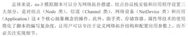
Complete writing sequence of simulation script [1-9]
1. Header file
Header file naming convention: "< module name > - module. H"
Directory of header file: [build/ns3]
Common header files are as follows:
#include "ns3/core-module.h" 			//  The core functions of ns-3 (such as simulating events and event scheduling) are defined, which must include
#include "ns3/network-module.h" 			//  The basic network components (such as network nodes, packets and addresses) of ns-3 are defined, which must include

#include "ns3/internet-module.h" 		//  TCP/IP protocol stack is defined
#include "ns3/applications-module.h" 	//  The packet sending and receiving model of the application layer (such as greedy model, ON/OFF model, etc.) is defined

#include "ns3/point-to-point-module.h"	//
#include "ns3/csma-module.h"			//
#include "ns3/wifi-module.h"			//

#include "ns3/mobility-module.h"		//
2. Namespace
using namespace ns3;
3. NS_LOG_COMPONENT_DEFINE
The function of the following line of code is to allow the macro in the Log system to be used in the script to define printing auxiliary information, such as ns for printing debugging information_ Log_ Errors and messages printed by bugs_ Log_ Error macro, etc
NS_LOG_COMPONENT_DEFINE ("FirstScriptExample");
Although this is an optional step, it is recommended to add it because this auxiliary information is useful for debugging code and understanding the simulation process
4. Preparations in main() function
From this step, the subsequent operations are completed in the main() function
  CommandLine cmd;
  cmd.Parse (argc, argv);												// Read command line parameters

  Time::SetResolution (Time::NS);										// Set minimum simulation time unit: ns

  LogComponentEnable ("UdpEchoClientApplication", LOG_LEVEL_INFO);		// Open the Log component and print the information of the specified Log component
  LogComponentEnable ("UdpEchoServerApplication", LOG_LEVEL_INFO);
The above steps are optional
5. Create network topology
With 1-4, now start to build the network topology
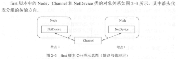
In ns-3, nodes, channels and network devices connecting channels in nodes are abstracted into three C + + classes: Node, Channel and NetDevice
For PPP, its corresponding network device class and channel class are PointToPointNetDevice and PointToPointChannel (protocol = channel + network device?)
Generally speaking, NetDevice implements link layer protocol and Channel implements physical layer protocol
  NodeContainer nodes;
  nodes.Create (2);														// Create network node

  PointToPointHelper pointToPoint;										// PPP channel helper class
  pointToPoint.SetDeviceAttribute ("DataRate", StringValue ("5Mbps"));	// Configure transmission rate attribute of PPP channel
  pointToPoint.SetChannelAttribute ("Delay", StringValue ("2ms"));		// Configure propagation delay attribute of PPP channel

  NetDeviceContainer devices;											// Create network device
  devices = pointToPoint.Install (nodes);								// Connecting nodes and channels
In the above code, the channel attribute is only configured when configuring the channel attribute, not the channel object. Two PPP network device objects (PointToPointNetDevice) and one PPP channel object (PointToPointChannel) are created in the pointtopointhhelper:: Install() function respectively. The two network device objects are installed in two nodes respectively, and then connected to the same channel object together. The Install() function returns a network device container NetDeviceContainer object. (network devices are middleware? Network devices are in nodes, and network devices are connected to channels, so finally return to the network device container and find nodes and channels according to network devices?)
So far, the network topology composed of nodes and channels has been built, and the communication between physical layer and link layer can be carried out. However, to run the application, the upper protocol stack needs to be installed
6. Install TCP/IP protocol family
The above upper layer protocol stack is the TCP/IP protocol family
The TCP/IP protocol family in ns-3 mainly includes: TCP and UDP in the transport layer; IP (IPv4 and IPv6) and ICMP (ICMPv4 and ICMPv6) of network layer; A series of routing protocols
The helper class for installing TCP/IP protocol stack for nodes is InternetStackHelper
  InternetStackHelper stack;
  stack.Install (nodes);		// Install the TCP/IP protocol stack for the nodes in the nodes container
The node with TCP/IP protocol stack installed cannot communicate directly, and it is also necessary to assign IP address to the network device of the node. In the first script, this part of the operation is completed by Ipv4AddressHelper/Ipv6AddressHelper (assign Ipv4/Ipv6 address)
  Ipv4AddressHelper address;						// Assign IP addresses to network devices
  address.SetBase ("10.1.1.0", "255.255.255.0");

  Ipv4InterfaceContainer interfaces = address.Assign (devices);
In the above code, the helper class Ipv4AddressHelper takes 10.1.1.0 as the starting address and 255.255.255.0 as the netmask, and assigns 10.1.1.1 and 10.1.1.2 IP addresses to the two hosts respectively
The first script network topology after adding TCP/IP protocol stack is shown in Figure 2-4
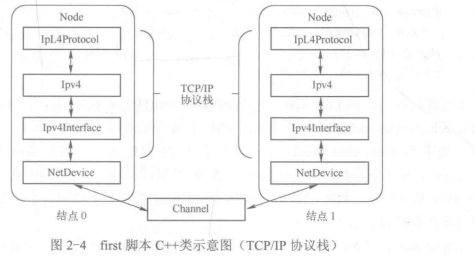
IpL4Protocol is the base class of TCP and UDP in the transport layer, IPv4 is the base class of IPv4 protocol in the network layer, NetDevice in the link layer and Channel in the physical layer
The IPv4 address assigned to the network device NetDevice is saved in the IPv4 interface Ipv4Interface object
A node can install multiple netdevices (like multi-mode mobile terminals with LTE and Wi Fi network devices), connect to multiple channels and have multiple IP addresses
So far, a wired network composed of two nodes has been built. Each node has installed PPP and TCP/IP protocol families from the physical layer to the transport layer. The two nodes can run various TCP/IP based applications for communication
7. Install the application
The application in ns-3 is the abstraction of the internal network communication function of the application in the physical world. i.e. simulates the sending and receiving behavior of packets
The C + + class corresponding to ns-3 Application layer protocol is Application, and its different subclasses define different packet sending and receiving behaviors. For example, BulkSendApplication uses greedy packet sending and receiving model, and OnOffApplication uses ONOFF packet sending and receiving model
The first script selects the application of udpeecho
  UdpEchoServerHelper echoServer (9);									// Monitor port 9

  ApplicationContainer serverApps = echoServer.Install (nodes.Get (1));	// Install the server program in node 1
  serverApps.Start (Seconds (1.0));
  serverApps.Stop (Seconds (10.0));

  UdpEchoClientHelper echoClient (interfaces.GetAddress (1), 9);		// Configure client program properties
  echoClient.SetAttribute ("MaxPackets", UintegerValue (1));
  echoClient.SetAttribute ("MaxPackets", TimeValue (Seconds (1.0)));
  echoClient.SetAttribute ("MaxPackets", UintegerValue (1024));

  ApplicationContainer clientApps = echoClient.Install (nodes.Get (0));	// Install client programs in node 0
  clientApps.Start (Seconds (2.0));
  clientApps.Stop (Seconds (10.0));
In the above code: the server-side assistant class UdpEchoHelper creates a server-side application echoServer in node 1. The echoServer starts to listen and receive the data of port 9 1.0s after the simulation is started; The client assistant class UdpEchoClientHelper creates a client application echoClient in node 0. echoClient sends a 1024B UDP packet to port 9 of node 1 2.0s after the simulation is started; After receiving the packet from port 9, echoServer returns a UDP packet of the same size to echoClient (the code is not written, and the UDP packet of the same size is returned, which is encapsulated?); Both applications stopped 10.0s after the simulation started.
"MaxPackets", "MaxPackets", "MaxPackets" and "MaxPackets" are three attributes of UdpEchoClient class, which respectively represent the maximum number of packets sent, the packet sending interval, the packet load and the byte size
8. Data generation
Generating data is a necessary function of network simulation, otherwise people will not be able to analyze network performance
Attribute configuration and data generation, one input and one output
9. Start and end
  Simulator::Run ();
  Simulator::Destroy ();
  return 0;
The above code is the last step of all ns-3 simulation scripts
The C + + simulation script is essentially a main() function, so the program finally needs to return 0 to tell the os that the program execution is successful
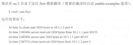
0.00369s is the sum of the transmission delay of the packet from node 0 to node 1 (the time spent sending the packet from the node to the channel) and the propagation delay (the time spent in the channel)

1054B=1024B (load) + 20B (IPv4 packet header) + 8B (UDP packet header) + 2B (PPP packet header)
The propagation delay of PPP channel is 0.002s, so the total one-way delay is 0.00369s (the result is accurate to 5 decimal places)