1. Download and install
Enter the official website download interface, and the link is as follows: OMNeT + + official website , select the appropriate operating system and version to download. (take windows as an example).
After downloading, unzip it to the specified folder and double-click the file mingwenv CMD, which can be completed according to the actual operation. (after the prompt for entering the command line appears, enter. / configure and make successively. It takes a long time and needs to wait patiently.)
After completing the above steps, click the interface in the ide to open the OMNet + + interface.
When entering the interface, you need to create a new folder to specify the workspace (the operation is the same as eclipse). The system default space is simple.
2. New project
After opening the OMNeT + + image interface, you can start creating your own display.
Click file - > New - > OMNeT + + project once in the menu bar, and the following interface appears:
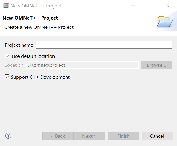
After entering the project name, click Next and select Empty Project. The storage space of the project is the workspace selected when OMNeT + + is opened.
You need to run an OMNeT + + emulator completely ned,. cc,. ini files represent the topology of the network, the running program (C + +) and the running entry of the network.
For beginners, you can first learn the examples in the simple directory where OMNeT is installed. The following part focuses on 18 simple examples of tictoc.
3.tictoc example
1.tictoc1
This is the first instance of OMNeT + +. As mentioned earlier, it is necessary to run a complete OMNeT program ned,. cc,. Ini three files. Before that, open tictoc1 ned,txc1.cc,omnetpp.ini.
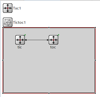
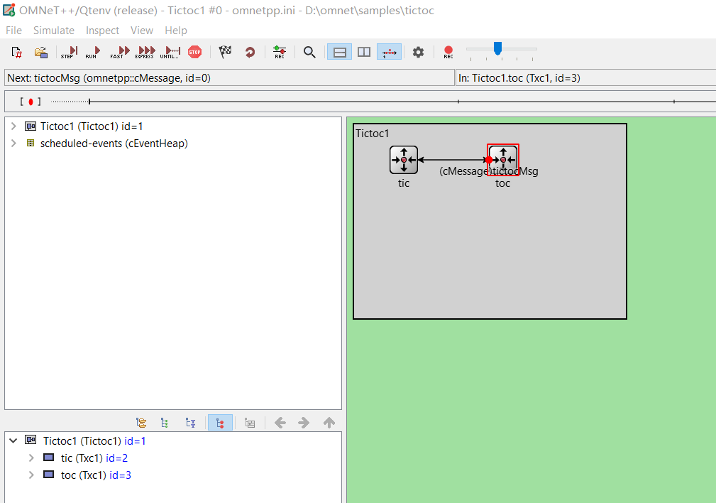
In Tictoc1 In Ned, you can see the topology as shown in the following figure: (in network Tictoc1, the positions of nodes tic and toc can be dragged freely)
After clicking source, you can see the code written in NED language, as follows:
simple Txc1
{
    @display("i=block/routing");  //position
    gates:
        input in;                //Input gate
        output out;              //Output gate
}


network Tictoc1                //network structure
{
    @display("bgb=383,273");   //colour
    submodules:
        tic: Txc1 {               //tic node
            @display("p=70,50");
        }
        toc: Txc1 {               //toc node
            @display("p=210,50");
        }
    connections:
        tic.out --> {  delay = 100ms; } --> toc.in;      //Network connection
        tic.in <-- {  delay = 100ms; } <-- toc.out;

}
In the code, simple defines a network node type, which includes an input gate in and an output gate ou. Then, a network named Tictoc1 is defined. The network includes two nodes tic and toc. The types of nodes are Txc1. Then, the connections section defines the connection between the two nodes: the out gate of tic is connected to the in gate of toc, and the transmission delay is 100ms; The in gate of tic is connected to the out gate of toc, and the transmission delay is 100ms.
At txc1 CC defines the information transmission and message processing methods between networks. The code is as follows:
#include <string.h>
#include <omnetpp.h>

using namespace omnetpp;

class Txc1 : public cSimpleModule     //The definition class, named network node, represents the information processing method of this kind of node
{
  protected:
    virtual void initialize() override;   //Initialization function
    virtual void handleMessage(cMessage *msg) override;    //How to handle messages after they are received
};

Define_Module(Txc1);

void Txc1::initialize()
{

    if (strcmp("tic", getName()) == 0) {
        cMessage *msg = new cMessage("tictocMsg");   //Create a new message
        send(msg, "out");  //Messages are sent from the out door
    }
}

void Txc1::handleMessage(cMessage *msg)
{
        send(msg, "out"); // After receiving the message, it is output directly from the out gate

}
There are already detailed comments in the code, because cc file is written based on C + +, using namespace is to use namespace, and strcmp is a string comparison function in C language. If the two strings are equal, 0 will be output. The initialize and handleMessage functions are initialization and message processing respectively. Define_Module () registers classes and nodes. This step is essential!
Yes ini file, you need to add a Network to the Network (you don't need to add it when running tictoc). After adding, the following results will appear in the code:
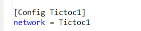
(more complex networks can inject parameters from here and talk about it later)
After completing the above three steps, run directly ned file to enter the simulation. The interface for entering the simulation is as follows:
Click Run to run. To run STEP by STEP, click STEP on the left; To run quickly, click FAST.
2.tictoc2
Compared with tictoc1, tictoc2 has the following codes:
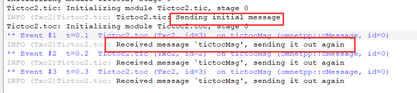
EV << "Sending initial message\n";
EV is similar to the total cout of C + + for output.
tictoc2 can see the output information when running. As follows:
3.tictoc3
Compared with tictoc2, the count attribute is added in the part of defining the class to control the number of message delivery. Every time a message is forwarded, the count value decreases by 1. When it decreases to 0, the message is deleted. Because there is no message, the program runs at this time. In the message processing function, the code is as follows:
void Txc3::handleMessage(cMessage *msg)
{
    // Increment counter and check value.
    counter--;
    if (counter == 0) {
        // If counter is zero, delete message. If you run the model, you'll
        // find that the simulation will stop at this point with the message
        // "no more events".
        EV << getName() << "'s counter reached zero, deleting message\n";
        delete msg;
    }
    else {
        EV << getName() << "'s counter is " << counter << ", sending back message\n";
        send(msg, "out");
    }
}
4.tictoc4
Compared with tictoc3, two parameters are added when defining network nodes. The code is as follows:
simple Txc4
{
    parameters:
        bool sendMsgOnInit = default(false); // whether the module should send out a message on initialization
        int limit = default(2);   // another parameter with a default value
        @display("i=block/routing");
    gates:
        input in;
        output out;
}
sendMsgOnInit is used to indicate whether to send messages during initialization, and limit is used to limit the number of messages sent The cc file directly assigns the value of limit to count.
Yes ini file, the registered information is as follows:
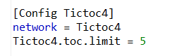
Directly assign 5 to the limit value of the toc node.
5.tictoc5
Compared with tictoc4, tictoc5 uses inheritance when defining network node types, defining toc and tic as different node types. As follows:
simple Txc5
{
    parameters:
        bool sendMsgOnInit = default(false);
        int limit = default(2);
        @display("i=block/routing");
    gates:
        input in;
        output out;
}


simple Tic5 extends Txc5
{
    parameters:
        @display("i=,cyan");
        sendMsgOnInit = true;   // Tic modules should send a message on init
}
Node type with inheritance relationship, using Define_Module() only needs its parent class to register.
6.tictoc6
Compared with the previous five examples, tictoc6 is being written cc file, the parameters of network node type are added; Constructors and destructors are introduced; And the self sending message model is added.
Class definition code is as follows:
class Txc6 : public cSimpleModule
{
  private:
    cMessage *event;  // pointer to the event object which we'll use for timing
    cMessage *tictocMsg;  // variable to remember the message until we send it back

  public:
    Txc6(); //Constructor
    virtual ~Txc6(); //Destructor

  protected:
    virtual void initialize() override;
    virtual void handleMessage(cMessage *msg) override;
};
The newly added event and tictocMeg attributes are used for self sending messages and sending messages respectively. The use of constructors and destructors is similar to that of C + +.
The self sending message is also added in the file to monitor whether the message sending times out. The code is as follows:
if (strcmp("tic", getName()) == 0) {
        EV << "Scheduling first send to t=5.0s\n";
        tictocMsg = new cMessage("tictocMsg");
        scheduleAt(5.0, event);   //Send autobiographical message
    }
In the initialize function, the tic node sends a message to itself at 5.0s. The content of the message is event. In the message processing function handleMessage, if the received message is event, the processing code is as follows:
if (msg == event) {
        EV << "Wait period is over, sending back message\n";
        send(tictocMsg, "out");
        tictocMsg = nullptr;
    }
That is, send out the contents in tictocMsg again.
7.tictoc7
Compared with the previous example, tictoc6 is being written In the ned file, the delay parameter is added for the network node type to prove the delay from receiving the message to forwarding the message. The specific value of delay is passed ini is produced by means of average distribution and normal distribution. In writing cc file, the probability of packet loss of 0.1 is considered.
In the. ini file, the code that generates the delay value is as follows:
[Config Tictoc7]
network = Tictoc7
# argument to exponential() is the mean; truncnormal() returns values from
# the normal distribution truncated to nonnegative values
Tictoc7.tic.delayTime = exponential(3s)
Tictoc7.toc.delayTime = truncnormal(3s,1s)
In the. cc file, the handleMessage function code is as follows:
void Txc7::handleMessage(cMessage *msg)
{
    if (msg == event) {
        EV << "Wait period is over, sending back message\n";
        send(tictocMsg, "out");
        tictocMsg = nullptr;
    }
    else {
        if (uniform(0, 1) < 0.1) {    //There is a probability of 0.1 to send packet loss
            EV << "\"Losing\" message\n";
            delete msg;
        }
        else {
            simtime_t delay = par("delayTime");

            EV << "Message arrived, starting to wait " << delay << " secs...\n";
            tictocMsg = msg;
            scheduleAt(simTime()+delay, event);
        }
    }
}
After receiving the message, first judge whether it is a spontaneous message eNet, and if so, send the message tictocmsg (in this way, the delay control of receiving and sending is realized); If not, simulate packet loss with a probability of 0.1. If there is no packet loss, send a message after delay to trigger MSG = = eNet to send tictocmsg.
8.tictoc8
Tic toc 8 first defines the node types of tic and toc networks respectively It is defined and registered separately in the cc file. Then, the function of timing replay is realized for tic node combined with self sending message. When sending a message in the initial stage, send a message to yourself after 1s. If a message has been received before, cancel the self sending and send another self sending message; If it is not received, the self sending message will be received after 1s. At this time, message sending and self sending messages will be carried out to achieve the purpose of timeout retransmission. The code is as follows:
void Tic8::handleMessage(cMessage *msg)
{
    if (msg == timeoutEvent) {
        EV << "Timeout expired, resending message and restarting timer\n";
        cMessage *newMsg = new cMessage("tictocMsg");
        send(newMsg, "out");
        scheduleAt(simTime()+timeout, timeoutEvent);
    }
    else {
        EV << "Timer cancelled.\n";
        cancelEvent(timeoutEvent);
        delete msg;

        cMessage *newMsg = new cMessage("tictocMsg");
        send(newMsg, "out");
        scheduleAt(simTime()+timeout, timeoutEvent);
    }
}
Tip: the processing function of toc is defined in the later part. There is a probability of packet loss of 0.1, but the timeout retransmission function of tic can be observed when packet loss occurs.
9.tictoc9
Based on tictoc8, the function of sending different messages is realized. That is, two functions generateNewMessage and sendCopyOf are added. The first function realizes the generation of new messages (according to the time series, the syntax is similar to C + +), and the second function realizes the sending of messages. The specific codes are as follows:
cMessage *Tic9::generateNewMessage()
{
    // Generate a message with a different name every time.
    char msgname[20];
    sprintf(msgname, "tic-%d", ++seq);  //String splicing
    cMessage *msg = new cMessage(msgname);
    return msg;
}
void Tic9::sendCopyOf(cMessage *msg)
{
// Duplicate message and send the copy.
cMessage *copy = (cMessage *)msg->dup(); //The forwarding message package is used to copy the current file description
send(copy, "out");
}
10.tictoc10
In the previous example, the network definition has only one input gate, one output gate and two nodes. In tictoc10, one node type, multiple gates and multiple identical node types are implemented in the form of array The definition code of the end part is as follows:
simple Txc10
{
    parameters:
        @display("i=block/routing");
    gates:
        input in[];  // declare in[] and out[] to be vector gates
        output out[];
}

network Tictoc10
{
    @display("bgb=300,258");
    submodules:
        tic[6]: Txc10 {
            @display("p=124,110;is=vl");
        }
    connections:
        tic[0].out++ --> {  delay = 100ms; } --> tic[1].in++;
        tic[0].in++ <-- {  delay = 100ms; } <-- tic[1].out++;

        tic[1].out++ --> {  delay = 100ms; } --> tic[2].in++;
        tic[1].in++ <-- {  delay = 100ms; } <-- tic[2].out++;

        tic[1].out++ --> {  delay = 100ms; } --> tic[4].in++;
        tic[1].in++ <-- {  delay = 100ms; } <-- tic[4].out++;

        tic[3].out++ --> {  delay = 100ms; } --> tic[4].in++;
        tic[3].in++ <-- {  delay = 100ms; } <-- tic[4].out++;

        tic[4].out++ --> {  delay = 100ms; } --> tic[5].in++;
        tic[4].in++ <-- {  delay = 100ms; } <-- tic[5].out++;
}
The direct connection of 0 / 1, 1 / 2, 1 / 4, 3 / 4 and 4 / 5 is realized.
Yes The main change in cc file is the addition of forwardMessage function. The code is as follows:
void Txc10::forwardMessage(cMessage *msg)
{
    int n = gateSize("out");
    int k = intuniform(0, n-1);

    EV << "Forwarding message " << msg << " on port out[" << k << "]\n";
    send(msg, "out", k);
}
Among all the output gates of the node, one is randomly selected for message transmission.
11.tictoc11
In TicToc, the channel model is used. The rest is unchanged compared with tictoc10, but after running, you can see the information transmission between the six nodes.
The definition code of network part is as follows:
network Tictoc11
{
    types:
        channel Channel extends ned.DelayChannel {
            delay = 100ms;
        }
    submodules:
        tic[6]: Txc11;
    connections:
        tic[0].out++ --> Channel --> tic[1].in++;
        tic[0].in++ <-- Channel <-- tic[1].out++;

        tic[1].out++ --> Channel --> tic[2].in++;
        tic[1].in++ <-- Channel <-- tic[2].out++;

        tic[1].out++ --> Channel --> tic[4].in++;
        tic[1].in++ <-- Channel <-- tic[4].out++;

        tic[3].out++ --> Channel --> tic[4].in++;
        tic[3].in++ <-- Channel <-- tic[4].out++;

        tic[4].out++ --> Channel --> tic[5].in++;
        tic[4].in++ <-- Channel <-- tic[5].out++;
}
12.tictoc12
In the previous example, the network node type definition part defines the input gate and output gate respectively. In tictoc, the two are directly combined into an inout gate. The code of the definition part is as follows:
simple Txc12
{
    parameters:
        @display("i=block/routing");
    gates:
        inout gate[];  // declare two way connections
}

network Tictoc12
{
    @display("bgb=550,332");
    types:
        channel Channel extends ned.DelayChannel
        {
            delay = 100ms;
        }
    submodules:
        tic[6]: Txc12 {
            @display("p=165,143");
        }
    connections:
        tic[0].gate++ <--> Channel <--> tic[1].gate++;
        tic[1].gate++ <--> Channel <--> tic[2].gate++;
        tic[1].gate++ <--> Channel <--> tic[4].gate++;
        tic[3].gate++ <--> Channel <--> tic[4].gate++;
        tic[4].gate++ <--> Channel <--> tic[5].gate++;
}
In the connection of connections, the in and out gates of two nodes are connected to each other. When sending messages, you only need to select the out gate. The code is as follows:
    // $o and $i suffix is used to identify the input/output part of a two way gate
    send(msg, "gate$o", k);
13.tictoc13
In the previous example, the information transmitted between two network nodes is system defined and only contains a message of string type statement. In tictoc13, the message type defined by itself is used. Message types are defined in TicToc In the MSG file, the code is as follows:
message TicTocMsg13
{
    int source;
    int destination;
    int hopCount = 0;
}
The network definition is consistent with tictoc12. After compiling the message file, the system will automatically generate tictoc13_m.cc and tictoc13_m.h two files, of which h file contains how to obtain relevant information about message, which is written in cc files need to be imported.
#include "tictoc13_m.h"
Yes In the cc file, the generateMessage function uses the relevant functions to obtain the message information, including setting relevant parameters, and using intuniform to randomly generate the destination. The code is as follows:
TicTocMsg13 *Txc13::generateMessage()
{
    int src = getIndex();  // our module index
    int n = getVectorSize();  // module vector size
    int dest = intuniform(0, n-2);   //Randomly generated destination
    if (dest >= src)
        dest++;

    char msgname[20];
    sprintf(msgname, "tic-%d-to-%d", src, dest);

    TicTocMsg13 *msg = new TicTocMsg13(msgname);
    msg->setSource(src);
    msg->setDestination(dest);
    return msg;
}
Yes cc file also uses the related function to get message information, which is in tictoc13_m.cc can obtain specific information about related functions. Readers need to learn this part patiently, which will not be repeated here.
14.tictoc14
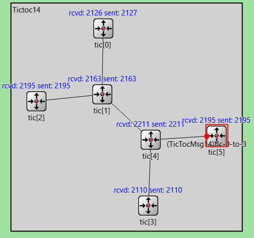
In tictoc14, two parameters numSent and numdeveloped are added to record the number of messages sent and received respectively and display them in the simulation interface. The code of refreshDisplay() function is as follows:
void Txc14::refreshDisplay() const
{
    char buf[40];
    sprintf(buf, "rcvd: %ld sent: %ld", numReceived, numSent);
    getDisplayString().setTagArg("t", 0, buf);
}
The effect diagram of operation is as follows:
15.tictoc15
tictoc15 adds chistogram hopcountstats on the basis of tictoc14; cOutVector hopCountVector; Two parameters are used to record the number of rebroadcasts (HOPS) experienced by the message during propagation and convert it into a statistical graph. The final finish() function displays the statistics of the simulation process at the end of the simulation program. The code is as follows:
void Txc15::finish()
{
    // This function is called by OMNeT++ at the end of the simulation.
    EV << "Sent:     " << numSent << endl;
    EV << "Received: " << numReceived << endl;
    EV << "Hop count, min:    " << hopCountStats.getMin() << endl;
    EV << "Hop count, max:    " << hopCountStats.getMax() << endl;
    EV << "Hop count, mean:   " << hopCountStats.getMean() << endl;
    EV << "Hop count, stddev: " << hopCountStats.getStddev() << endl;

    recordScalar("#sent", numSent);
    recordScalar("#received", numReceived);

    hopCountStats.recordAs("hop count");
}
The effect of operation is as follows:
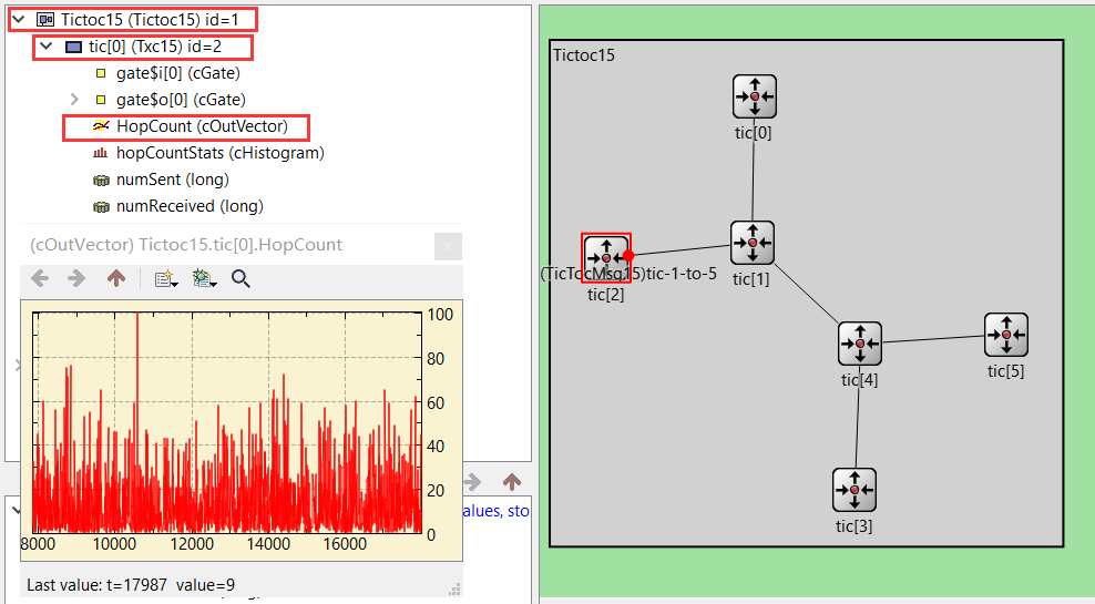
Click Tictoc15 on the left, select a node to be observed, and then double-click HopCount (outvector) to see a statistical chart (you must run enough data to observe, you can click FAST)
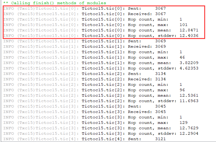
After the simulation (click STOP), click the following button in the taskbar to see the running data statistics results:

The results are as follows:
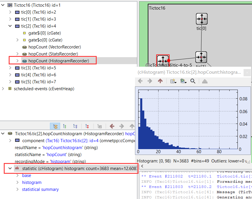
16.tictoc16
Another parameter, @ simsignal, is used in tictoc16_ t arrivalSignal; Record the hops of message forwarding in the form of signal Add the following information to the ini file:
[Config Tictoc16]
network = Tictoc16
**.tic[2].hopCount.result-recording-modes = +histogram
**.tic[0..2].hopCount.result-recording-modes = -vector
The statistical chart can be seen in tic[2]. The opening method is similar to tictoc15, and the operation effect is as follows:
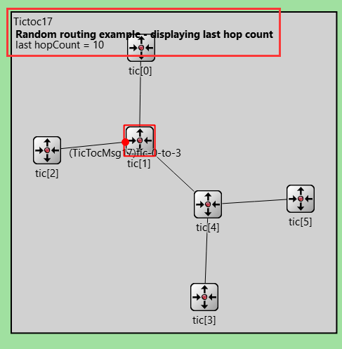
17.tictoc17
The display information in the simulation interface is added in tictoc, and the core code is as follows:
if (hasGUI()) {
            char label[50];
            // Write last hop count to string
            sprintf(label, "last hopCount = %d", hopcount);
            // Get pointer to figure
            cCanvas *canvas = getParentModule()->getCanvas();
            cTextFigure *textFigure = check_and_cast<cTextFigure*>(canvas->getFigure("lasthopcount"));
            // Update figure text
            textFigure->setText(label);
        }
The results of the operation are as follows:
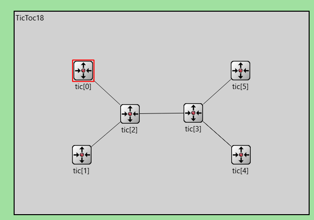
18.tictoc18
tictoc18 passed ini file sets the simulation time limit, parameter limit and the number of repetitions of each step. The code is as follows:
[Config TicToc18]
network = TicToc18
sim-time-limit = 250000s
**.tic[2].hopCount.result-recording-modes = +histogram
**.tic[*].hopCount.result-recording-modes = +vector
*.numCentralNodes = ${N=2..100 step 2}
repeat = 4
In addition, tictoc18 changes the display shape of the network and transforms the topology of the network into a dumbbell shape. If the value of numCentralNodes is changed to 2 in the network definition, the effect is more obvious. The definition code of the network part is as follows:
simple Txc18 extends Txc16
{
}

network TicToc18
{
    parameters:
        int numCentralNodes = default(2);
        @display("bgb=604,416");
    types:
        channel Channel extends ned.DelayChannel
        {
            delay = 100ms;
        }
    submodules:
        tic[numCentralNodes+4]: Txc18;
    connections:
        // connect the 2 nodes in one side to the central nodes
        tic[0].gate++ <--> Channel <--> tic[2].gate++;
        tic[1].gate++ <--> Channel <--> tic[2].gate++;
        // connect the central nodes together
        for i=2..numCentralNodes+1 {
            tic[i].gate++ <--> Channel <--> tic[i+1].gate++;
        }
        // connect the 2 nodes on the other side to the central nodes
        tic[numCentralNodes+2].gate++ <--> Channel <--> tic[numCentralNodes+1].gate++;
        tic[numCentralNodes+3].gate++ <--> Channel <--> tic[numCentralNodes+1].gate++;
}
The effect of operation is as follows: