The fourth picture makes spark, because there is spark interference in the welding process, and it has a great impact.
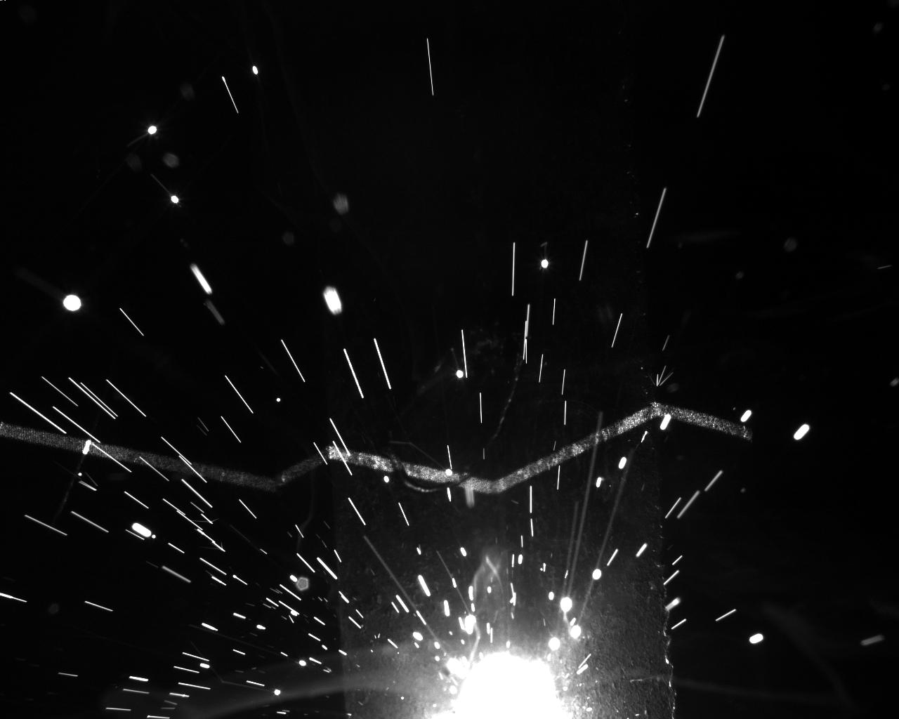
Sparks have a great influence on the image. Large sparks directly affect some characteristics of steel plate.
My first idea is to use contour extraction to calculate the contour area. In a certain range, I think that the steel plate, which is copied to another space map (the same size as the original map), can extract the intermediate welding points, but large sparks will have an impact on the image.
The code is as follows: (only a part is written and the moment of the contour is calculated)
#include <opencv2/opencv.hpp>
#include "opencv2/highgui/highgui.hpp"
#include "opencv2/imgproc/imgproc.hpp"
#include <iostream>
#include <cstdlib>
using namespace cv;
using namespace std;
#define WINDOW_NAME "[Subpixel Corner Detection]
Mat g_srcImage, g_grayImage;
int g_maxCornerNumber = 20; //Point Initial Value
int g_maxTrackbarNumber = 500; //Points on line
//RNG g_rng(12345);//Initialized Random Number Generator
void on_GoodFeaturesToTrack(int, void*) //Callback function responding to slider movement
{
if (g_maxCornerNumber <= 7) { g_maxCornerNumber = 7; } //Treatment of variables less than or equal to 1
vector<Point2f> corners; //Parameter preparation of Shi-Tomasi algorithm (goodFeatures ToTrack function)
double qualityLevel = 0.01; //Minimum acceptable eigenvalues for corner detection
double minDistance = 10; //Minimum distance between corners
int blockSize = 3; //Neighborhood range specified when calculating derivative autocorrelation matrix
double k = 0.04; //weight coefficient
Mat copy = g_srcImage.clone();
//Shi-Tomasi corner detection
goodFeaturesToTrack
(g_grayImage, //input image
corners, //Output vector of detected corners
g_maxCornerNumber, //Maximum number of corners
qualityLevel, //Minimum acceptable eigenvalues for corner detection
minDistance, //Minimum distance between corners
Mat(), //Region of Interest
blockSize, //Neighborhood range specified when calculating derivative autocorrelation matrix
false, //No Harris corner detection
k); //weight coefficient
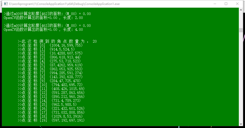
cout << "\n\t>-The number of corners detected is:" << corners.size() << endl;
//Parameter Setting for Sub-pixel Corner Detection
Size winSize = Size(5, 5);
Size zeroZone = Size(-1, -1);
TermCriteria criteria = TermCriteria(TermCriteria::EPS + TermCriteria::MAX_ITER, 40, 0.001);
//Calculate sub-pixel corner position
cornerSubPix(g_grayImage, corners, winSize, zeroZone, criteria);
for (int i = 0; i < corners.size(); i++)
{
circle(copy, corners[i], 3, Scalar(0, 255, 0), -1, 8, 0);
cout << " \t>>Point coordinates[" << i << "] (" << corners[i].x << "," << corners[i].y << ")" << endl;
}
imshow(WINDOW_NAME, copy);
}
int main(int argc, char** argv)
{
Mat srcImage = imread("4.jpg", 0); //Load the original graph binary graph pattern
imshow("Primitive graph", srcImage);
Mat element = getStructuringElement(MORPH_RECT, Size(2,2)); //Define Kernel, Open Operations
morphologyEx(srcImage, srcImage, MORPH_OPEN, element); //Conduct morphological open operations
Mat dstImage = Mat::zeros(srcImage.rows, srcImage.cols, CV_8UC3); //Initialization result graph
srcImage = srcImage > 80; //The srcImage is larger than the threshold. That part
imshow("The original graph after thresholding", srcImage);
vector<vector<Point> > contours;
vector<Vec4i> hierarchy;
findContours(srcImage, contours, hierarchy, RETR_CCOMP, CHAIN_APPROX_SIMPLE);
vector<Moments> mu(contours.size()); // Computational moment
for (unsigned int i = 0; i < contours.size(); i++)
{
mu[i] = moments(contours[i], false);
}
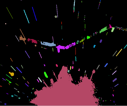
int index = 0; //Traverse all top-level contours to draw the colors of each connection component in random colors
for (; index >= 0; index = hierarchy[index][0])
{
Scalar color(rand() & 255, rand() & 255, rand() & 255);
drawContours(dstImage, contours, index, color, FILLED, 8, hierarchy);
}
printf("\t Output content: Area and contour length\n"); // Calculating contour area by m00 and comparing with OpenCV function
for (unsigned int i = 0; i< contours.size(); i++)
{
printf(" >adopt m00 Calculate the contour[%d]Area: (M_00) = %.2f \n OpenCV Area calculated by function=%.2f , length: %.2f \n\n", i, mu[i].m00, contourArea(contours[i]), arcLength(contours[i], true));
}
system("color 2F");
g_srcImage = dstImage;
cvtColor(g_srcImage, g_grayImage, COLOR_BGR2GRAY);
namedWindow(WINDOW_NAME, WINDOW_AUTOSIZE); //Create windows and sliders and initialize display and callback functions
createTrackbar("Maximum Angle Points", WINDOW_NAME, &g_maxCornerNumber, g_maxTrackbarNumber, on_GoodFeaturesToTrack);
on_GoodFeaturesToTrack(0, 0);
waitKey(0);
return 0;
}
The results show that the area of the steel plate can be extracted, but it is possible that the large sparks just block the corner points, so this method is not feasible, and it will not continue to do.
I came up with the second method, but only with video files. The idea is to use background removal to compare the first frame and the second frame of video (to ensure that sparks move from one place to another in this a frame time). In this way, the sparks can be extracted, and the sparks can be compared with the image of the last a frame, so that the sparks can be removed and the features on the steel plate can be further processed. Time does not do this part.
Now ask for help, I hope you can have better suggestions.