Requirements:
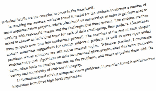
In image processing, sometimes due to the inconsistent angle of the photo taken, the resulting image has a certain degree of offset and needs to be corrected, such as the following two pictures.
Figure 1
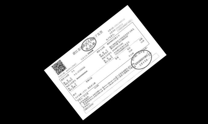
Figure 2
For example, Fig. 1, what should I do if I want to correct the labels and cut them out entirely to save them?That involves image correction and area of interest extraction.
In general, there are at least a few knowledge stores for image correction:
- Contour Extraction Technology
- Hoff Transform Knowledge
- ROI Area of Interest Knowledge
Following is a step-by-step analysis of how image correction can be achieved by taking label correction, invoice correction, and text correction as examples.
First analyze how to correct labels.
For example, if we want to correct this label, what should we think?
First, analyze the characteristics of this picture.
In this image, the label has a certain tilt angle, but the angle is not large; the background of the label is black, and the edges of the label should be more visible.
Yes, we'll grab the edge of the tag and make an article!Can we find the outline of the label first (the outline is a big rectangle, of course), then surround it with a rectangle to get its rotation angle, and then rotate it according to the angle obtained, so that we can not rectify it!
Summarize the steps in more detail:
Grayscale Picture
Threshold Binarization
Detecting contours
Find the bounding matrix of the contour and get the angle
Rotation correction according to angle
Contour extraction of rotated images
Cut out the image area inside the outline to make a separate image
I named the correction algorithm based on contour extraction because the key technique is to obtain the rotation angle from the contour.
The code implementation refers to the following sample code,
void GetContoursPic(Mat srcImg, Mat dstImg)
{
	imshow("Original Map", srcImg);
	Mat gray, binImg;
	//Grayscale
	cvtColor(srcImg, gray, COLOR_RGB2GRAY);
	//Imshow (gray scale);
	//Binarization
	threshold(gray, binImg, 60, 200, CV_THRESH_BINARY);
	///////////////////////////////////////////
	imshow("Binarization", binImg);
	waitKey(0);

	vector<vector<Point> > contours;
	vector<Rect> boundRect(contours.size());
	//Note that the fifth parameter is CV_RETR_EXTERNAL, only the frame is retrieved
	findContours(binImg, contours, CV_RETR_EXTERNAL, CV_CHAIN_APPROX_NONE);
	///////////////////////////////////////////////////
	cout << contours.size() << endl;

	for (int i = 0; i < contours.size(); i++)
	{
		//Coordinates to be obtained
		CvPoint2D32f rectpoint[4];
		CvBox2D rect = minAreaRect(Mat(contours[i]));
		//Get four vertex coordinates
		cvBoxPoints(rect, rectpoint);
		//Angle to horizontal line
		float angle = rect.angle;
		//cout << angle << endl;
		int line1 = sqrt((rectpoint[1].y - rectpoint[0].y)*(rectpoint[1].y - rectpoint[0].y) + (rectpoint[1].x - rectpoint[0].x)*(rectpoint[1].x - rectpoint[0].x));
		int line2 = sqrt((rectpoint[3].y - rectpoint[0].y)*(rectpoint[3].y - rectpoint[0].y) + (rectpoint[3].x - rectpoint[0].x)*(rectpoint[3].x - rectpoint[0].x));
		////rectangle(binImg, rectpoint[0], rectpoint[3], Scalar(255), 2);
		////Direct pass with too small area
		//if (line1 * line2 < 600)
		//{
		//	continue;
		//}

		double area = contourArea(contours[i]);
		if (area<3000)
		{
			continue;
		}

		//The rotation angle is different for the square to be placed horizontally.Vertical, add 90 degrees to it, turn it over
		if (line1 > line2)
		{
			angle = 90 + angle;
		}

		//Create a new map of interest the same size as the original
		Mat RoiSrcImg(srcImg.rows, srcImg.cols, CV_8UC3); //Note that CV_8UC3 must be selected here
		RoiSrcImg.setTo(0); //Color set to black
		//Imshow (New ROI, RoiSrcImg);
		//Fill in the resulting outline
		drawContours(binImg, contours, -1, Scalar(255), FILLED);

		//Cutting to RoiSrcImg
		srcImg.copyTo(RoiSrcImg, binImg);

		//Let's show it again. Everything except the area of interest is black.
		//namedWindow("RoiSrcImg", 1);
		//imshow("RoiSrcImg", RoiSrcImg);

		//Create a rotated image
		Mat RatationedImg(RoiSrcImg.rows, RoiSrcImg.cols, CV_8UC1);
		RatationedImg.setTo(0);
		//Rotate RoiSrcImg
		Point2f center = rect.center;  //Center Point
		Mat M2 = getRotationMatrix2D(center, angle, 1);//Computing the rotation plus scaling transformation matrix
		warpAffine(RoiSrcImg, RatationedImg, M2, RoiSrcImg.size(), 1, 0, Scalar(0));//affine transformation
		//imshow("After Rotation", RatationedImg);
		imwrite("r.jpg", RatationedImg); //Save the corrected picture
		//waitKey(0);
		//destroyAllWindows();

	}
The above algorithm can handle both label and invoice skew correction very well, but it is not ideal for text correction because the label image and invoice image have distinct boundary outlines, while the text image does not.The background of the text image is white, so we cannot extract outlines and rotate corrections like rectangular objects with clear boundaries such as labels and invoices.
After in-depth analysis, it can be seen that although text-based images do not have obvious edge outlines, they have an important feature: each line of text is a straight line shape, and these lines are parallel!
In this case, I think of another method: a correction algorithm based on line detection.
First, I introduce my algorithm ideas:
Detecting all straight lines in an image using Hoff line transformation
Calculate the oblique angle of each line and average them
Correct by tilt angle rotation
Finally, crop the picture according to the text size
Then the implementation algorithm of OpenCV is given, referring to the void txtImgRecify (Mat src, Mat & dst) function of the sample code.
//Degree conversion
double CImageOrientationCorrection::DegreeTrans(double theta)
{
	double res = theta / CV_PI * 180;
	return res;
}

//Rotate image degree angle counterclockwise (original size)
void CImageOrientationCorrection::rotateImage(Mat src, Mat& img_rotate, double degree)
{
	//Rotation center is image center
	Point2f center;
	center.x = float(src.cols / 2.0);
	center.y = float(src.rows / 2.0);
	int length = 0;
	length = sqrt(src.cols*src.cols + src.rows*src.rows);
	//Computing affine transformation matrix of two-dimensional rotation
	Mat M = getRotationMatrix2D(center, degree, 1);
	warpAffine(src, img_rotate, M, Size(length, length), 1, 0, Scalar(255, 255, 255));//Affine transformation, background color filled with white
}

//Calculating angles by Hoff transformation
double CImageOrientationCorrection::CalcDegree(const Mat &srcImage, Mat &dst)
{
	Mat midImage, dstImage;

	Canny(srcImage, midImage, 50, 200, 3);
	cvtColor(midImage, dstImage, CV_GRAY2BGR);

	//Detecting Lines by Hoff Transform
	vector<Vec2f> lines;
	//The fifth parameter is the threshold. The larger the threshold, the higher the detection accuracy.
	HoughLines(midImage, lines, 1, CV_PI / 180, 300, 0, 0);
	//cout << lines.size() << endl;
	//Threshold setting is not good because the image is different, because the threshold setting is too high to detect straight lines, the threshold is too low too many straight lines, the speed is very slow
	//So three thresholds are set from high to low, and a suitable threshold can be fixed after a lot of experimentation.
	if (!lines.size())
	{
		HoughLines(midImage, lines, 1, CV_PI / 180, 200, 0, 0);
	}
	//cout << lines.size() << endl;
	if (!lines.size())
	{
		HoughLines(midImage, lines, 1, CV_PI / 180, 150, 0, 0);
	}
	//cout << lines.size() << endl;
	if (!lines.size())
	{
		cout << "No straight lines detected!" << endl;
		return ERROR_RETURNS;
	}
	float sum = 0;
	//Draw each segment in turn
	for (size_t i = 0; i < lines.size(); i++)
	{
		float rho = lines[i][0];
		float theta = lines[i][1];
		Point pt1, pt2;
		//cout << theta << endl;
		double a = cos(theta), b = sin(theta);
		double x0 = a * rho, y0 = b * rho;
		pt1.x = cvRound(x0 + 1000 * (-b));
		pt1.y = cvRound(y0 + 1000 * (a));
		pt2.x = cvRound(x0 - 1000 * (-b));
		pt2.y = cvRound(y0 - 1000 * (a));
		//Select only the lowest angle as the rotation angle
		sum += theta;
		//Scalar function to adjust segment color
		line(dstImage, pt1, pt2, Scalar(55, 100, 195), 1, LINE_AA);

		imshow("Line Detection Graph", dstImage);
	}
	//Averaging all angles makes rotation better
	float average = sum / lines.size();
	cout << "average theta:" << average << endl;
	double angle = DegreeTrans(average) - 90;
	rotateImage(dstImage, dst, angle);
	//imshow("Line detection effect Figure 2", dstImage);
	return angle;
}

void CImageOrientationCorrection::txtImgRecify(Mat src, Mat& dst)
{
	double degree;
	imshow("Original Map", src);
	//Tilt Angle Correction
	degree = CalcDegree(src, dst);
	if (degree == ERROR_RETURNS)
	{
		cout << "Correction failed!" << endl;
		return;
	}
	rotateImage(src, dst, degree);
	cout << "angle:" << degree << endl;
	imshow("After rotation adjustment", dst);
	//Estimate the length and width of the text based on prior knowledge before clipping it
	Mat resulyImage = dst(Rect(0, 0, dst.cols, 500));
	imshow("After cropping", resulyImage);
	imwrite("recified.jpg", resulyImage);
	waitKey(0);
	destroyAllWindows();
}
We found that the corrected image had more white space, which affected viewing, so further cropping was needed to preserve the text area.
You can see that the correction algorithm based on line detection works really well in text processing!
Finally, we summarize the scenarios in which the two algorithms are applied:
The correction algorithm based on contour extraction is more suitable for rectangular shape and obvious boundary correction such as license plate, ID card, Renminbi, book, label, invoice.
The correction algorithm based on line detection is more suitable for text class correction.
Complete sample code to get addresses: https://download.csdn.net/download/shufac/12041413
Reference resources: https://www.cnblogs.com/skyfsm/p/6902524.html

