This chapter uses gpio interrupt to realize key driving, and the focus is to understand HDF gpio framework
1, Driver code
Refer to the preparation of led driver in the previous chapter to realize the driver in this chapter.
You can repeat it according to the writing steps of led driver in the previous chapter. The difference between button driver and led driver lies in GPIO pin, initialization code, interrupt related code, etc
1.1. button drive
In the key driver button Add gpio header file in C:
#include "gpio_if.h"
In the initialization function, by reading the button_config.hcs to get the GPIO number of the key. Then call gpio_. if. H, set the interrupt callback function mycallbackfunction, and finally enable the interrupt.
// Interface that drives the initial of its own business
int32_t HdfButtonDriverInit(struct HdfDeviceObject *device)
{
    int32_t ret;

    struct Stm32Mp1Button *btn = &g_Stm32Mp1IButton;
    //Get gpio pin number
    Stm32ButtonReadDrs(btn,device->property);

    //You don't need to set it as input here, because IO will be set as input in GpioSetIrq
    //GpioSetDir(btn->gpioNum, GPIO_DIR_IN);

    /* Set GPIO pin interrupt callback function as mycallbackfunction, input parameter as GPIO object, and interrupt trigger mode as rising edge trigger */
    ret = GpioSetIrq(g_Stm32Mp1IButton.gpioNum, OSAL_IRQF_TRIGGER_RISING, MyCallBackFunc, (void *)device);
    if (ret != 0) {
        HDF_LOGE("GpioSetIrq: failed, ret %d\n", ret);
        return HDF_FAILURE;
    }

    /* Enable IO pin interrupt */
    ret = GpioEnableIrq(btn->gpioNum);
    if (ret != 0) {
        HDF_LOGE("GpioEnableIrq: failed, ret %d\n", ret);
        return HDF_FAILURE;
    }

    return HDF_SUCCESS;
}
Interrupt callback function:
Count the number of key presses in the interrupt callback function, and then send the number to the application layer. Here, messages are sent to the application layer through the message management mechanism of HDF. This part will be discussed later.
When HdfDeviceSendEvent() is successfully executed, the listening function of the application will be executed and the led will be flipped in the callback function.
/* Interrupt service function
*/
int32_t MyCallBackFunc(uint16_t gpio, void *data)
{
    global_data++;  //Global variable to record the number of key presses

    //Get device driver
    struct HdfDeviceObject *deviceObject = (struct HdfDeviceObject *)data;

    //Create a buf to transfer data to the application layer
    struct HdfSBuf *send_buf = HdfSBufObtainDefaultSize();

    //global_data write buf
    HdfSbufWriteUint16(send_buf,global_data);

    //Transfer the data in buf to the application subscribing to the button driven service
    HdfDeviceSendEvent(deviceObject,520,send_buf);

    //Recycle buf
    HdfSBufRecycle(send_buf);

    return 0;
}
1.2 gpio driver
1.2.1 gpio core layer
The above GPIO operation functions are controlled by gpio_if.h provides, while GPIO_ if. GPIO just right_ core. C, shielding the GPIO controller
For example, the following function actually calls GPIO_ core. GpioCntlrSetIrq() in C.
int32_t GpioSetIrq(uint16_t gpio, uint16_t mode, GpioIrqFunc func, void *arg)
{
    return GpioCntlrSetIrq(GpioGetCntlr(gpio), GpioToLocal(gpio), mode, func, arg);
}
And gpio_core.c is the abstraction of hardware gpio controller, through which specific gpio level, input / output mode, interrupt and so on can be configured.
struct GpioCntlr {
    struct IDeviceIoService service;    //gpio no service
    struct HdfDeviceObject *device;     //gpio equipment (hcs)
    struct GpioMethod *ops;             //GPIO operation mode, by stm32mp1_gpio.c implementation
    struct DListHead list;
    OsalSpinlock spin;
    uint16_t start;
    uint16_t count;
    struct GpioInfo *ginfos;            //Array (see below)
    void *priv;                         //Parameters of callback function
};
gpio_ core. The functions in C are various methods to call the controller:
int32_t GpioCntlrWrite(struct GpioCntlr *cntlr, uint16_t local, uint16_t val)
{
	......
    return cntlr->ops->write(cntlr, local, val);
}
int32_t GpioCntlrRead(struct GpioCntlr *cntlr, uint16_t local, uint16_t *val)
{
	......
    return cntlr->ops->read(cntlr, local, val);
}

int32_t GpioCntlrSetDir(struct GpioCntlr *cntlr, uint16_t local, uint16_t dir)
{
	......
    return cntlr->ops->setDir(cntlr, local, dir);
}

int32_t GpioCntlrGetDir(struct GpioCntlr *cntlr, uint16_t local, uint16_t *dir)
{
	......
    return cntlr->ops->getDir(cntlr, local, dir);
}
It should be noted that each interrupt controller has an array of ginfos, which is defined as follows:
//Describes all GPIO interrupt callback functions and parameters, usually as an array (I don't know why I choose this name)
struct GpioInfo {
    GpioIrqFunc irqFunc;				//Callback function of specific gpio pin
    void *irqData;						//Function parameters
};
The MyCallBackFunc() function set by calling GpioSetIrq() is saved in a specific location of this array. When the gpio pin interrupt is generated, the interrupt function will find the ginfo array according to the gpio controller, and then take MyCallBackFunc() from the array to execute. So the function in ginfo array is called interrupt callback function.
The following function is gpio_core.c provides a callback interface. The interrupt function needs to call this function to realize the callback mycallbackfunction(), such as IrqHandleNoShare() in 2.2.2
//It is called by the gpio interrupt function and is used to call the gpio callback function set by the user
void GpioCntlrIrqCallback(struct GpioCntlr *cntlr, uint16_t local)
{
    struct GpioInfo *ginfo = NULL;
    //Check gpio controller and ginfos
    if (cntlr != NULL && local < cntlr->count && cntlr->ginfos != NULL) {
        ginfo = &cntlr->ginfos[local];
        if (ginfo != NULL && ginfo->irqFunc != NULL) {
            //Execute interrupt callback function
            (void)ginfo->irqFunc(local, ginfo->irqData);
        } else {
            HDF_LOGW("GpioCntlrIrqCallback: ginfo or irqFunc is NULL!");
        }
    } else {
        HDF_LOGW("GpioCntlrIrqCallback: invalid cntlr(ginfos) or loal num:%u!", local);
    }
}
The comments on the source code of GpioCntlrSetIrq() are as follows: it implements two functions:
- Set callback function.
- Call gpio driver and initialize the hardware configuration related to interrupt: cntlr - > Ops - > setirq (cntlr, local, mode, thefunc, thedata);
//Set gpio interrupt callback function to controller
int32_t GpioCntlrSetIrq(struct GpioCntlr *cntlr, uint16_t local, uint16_t mode, GpioIrqFunc func, void *arg)
{
    int32_t ret;
    uint32_t flags;
    GpioIrqFunc theFunc = func;
    void *theData = arg;
    struct GpioIrqBridge *bridge = NULL;
    void *oldFunc = NULL;
    void *oldData = NULL;

    //Check the parameters
    if (cntlr == NULL || cntlr->ginfos == NULL) {
        return HDF_ERR_INVALID_OBJECT;
    }
    if (local >= cntlr->count) {
        return HDF_ERR_INVALID_PARAM;
    }
    if (cntlr->ops == NULL || cntlr->ops->setIrq == NULL) {
        return HDF_ERR_NOT_SUPPORT;
    }

    //The interrupt thread is used to handle the interrupt, and the callback function will be executed in the interrupt thread
    if ((mode & GPIO_IRQ_USING_THREAD) != 0) {
        bridge = GpioIrqBridgeCreate(cntlr, local, func, arg);
        //Set the interrupt service function to GpioIrqBridgeFunc, which is used to release semaphores in interrupts
        if (bridge != NULL) {
            theData = bridge;
            theFunc = GpioIrqBridgeFunc;
        }
        if (bridge == NULL) {
            return HDF_FAILURE;
        }
    }

    (void)OsalSpinLockIrqSave(&cntlr->spin, &flags);
    //Save old interrupt function
    oldFunc = cntlr->ginfos[local].irqFunc;
    oldData = cntlr->ginfos[local].irqData;

    //Set the new interrupt function to the interrupt array of the controller
    cntlr->ginfos[local].irqFunc = theFunc;
    cntlr->ginfos[local].irqData = theData;

    //Initialization interrupt: set register and callback function
    ret = cntlr->ops->setIrq(cntlr, local, mode, theFunc, theData);
    if (ret == HDF_SUCCESS) {

        if (oldFunc == GpioIrqBridgeFunc) {
            //The previous interrupt used an interrupt thread, so you want to delete the thread
            GpioIrqBridgeDestroy((struct GpioIrqBridge *)oldData);
        }
    } else {
        cntlr->ginfos[local].irqFunc = oldFunc;
        cntlr->ginfos[local].irqData = oldData;
        if (bridge != NULL) {
            GpioIrqBridgeDestroy(bridge);
            bridge = NULL;
        }
    }
    (void)OsalSpinUnlockIrqRestore(&cntlr->spin, &flags);
    return ret;
}
1.2.2 gpio driver
gpio_core.c only provides a "model" of GPIO controller. The specific GPIO controller needs to be implemented by the driver developer according to the chip platform. In this example, stm32mp157 has been officially implemented by little bear school. In the directory / device/st/drivers/gpio /:
stm32mp1_ gpio. The implementation of C refers to [openharmony gpio driver development guide]( zh-cn/device-dev/driver/driver-platform-gpio-develop.md · OpenHarmony/docs - Gitee.com ). It is best for readers to read the guide first.
First, understand the gpio controller structure of stm32:
This structure is customized by the driver developer and must contain the struct GpioCntlr member.
//Describes a GPIO controller that controls all GPIO ports
struct Stm32GpioCntlr {
    struct GpioCntlr cntlr;             //gpio core layer controller
    volatile unsigned char *regBase;   //Address after register mapping
    EXTI_TypeDef *exitBase;     //ditto
    uint32_t gpioPhyBase;   //gpio register physical base address
    uint32_t gpioRegStep;   //gpio Register Offset step
    uint32_t irqPhyBase;    //Physical base address of external interrupt register
    uint32_t iqrRegStep;    //External interrupt register offset step
    uint16_t groupNum;      //Number of gpio groups
    uint16_t bitNum;        //Number of pins per gpio group
    struct GpioGroup *groups;   //gpio port (an array)
};

//Describe a gpio port, such as gpioa and gpiob
struct GpioGroup {
    volatile unsigned char *regBase;    //Register mapping address (register address mapping)
    EXTI_TypeDef *exitBase;     //External interrupt base address
    unsigned int index;         //Port subscript
    OsalIRQHandle irqFunc;      //Port interrupt handling function
    OsalSpinlock lock;
};
According to the above structure, stm32mp1_ gpio. In C, in addition to implementing the struct GpioCntlr cntlr of the core layer, we also need to obtain the hardware configuration such as register address.
This can be reflected in the gpio driver initialization function:
//gpio driver initialization
//Driver profile GPIO_ config. Hardware information such as register address is defined in HCS. After the driver is successfully loaded, these information will be transferred to HCS through device - > property
static int32_t GpioDriverInit(struct HdfDeviceObject *device)
{
    int32_t ret;
    struct Stm32GpioCntlr *stm32gpio = &g_Stm32GpioCntlr;

    dprintf("%s: Enter", __func__);
    if (device == NULL || device->property == NULL) {
        HDF_LOGE("%s: device or property NULL!", __func__);
        return HDF_ERR_INVALID_OBJECT;
    }
    //Get hcs configuration information to stm32gpio
    ret = Stm32GpioReadDrs(stm32gpio, device->property);
    if (ret != HDF_SUCCESS) {
        HDF_LOGE("%s: get gpio device resource fail:%d", __func__, ret);
        return ret;
    }
    //Check configuration information
    if (stm32gpio->groupNum > GROUP_MAX || stm32gpio->groupNum <= 0 || stm32gpio->bitNum > BIT_MAX ||
        stm32gpio->bitNum <= 0) {
        HDF_LOGE("%s: invalid groupNum:%u or bitNum:%u", __func__, stm32gpio->groupNum,
                 stm32gpio->bitNum);
        return HDF_ERR_INVALID_PARAM;
    }
    //Map and save the register address, and then operate the register only through the mapped address
    stm32gpio->regBase = OsalIoRemap(stm32gpio->gpioPhyBase, stm32gpio->groupNum * stm32gpio->gpioRegStep);
    if (stm32gpio->regBase == NULL) {
        HDF_LOGE("%s: err remap phy:0x%x", __func__, stm32gpio->gpioPhyBase);
        return HDF_ERR_IO;
    }
    //Map the address of the exti external interrupt register
    stm32gpio->exitBase = OsalIoRemap(stm32gpio->irqPhyBase, stm32gpio->iqrRegStep);
    if (stm32gpio->exitBase == NULL) {
        dprintf("%s: OsalIoRemap fail!", __func__);
        return -1;
    }
    //Initialize stm32gpio - > groups array
    ret = InitGpioCntlrMem(stm32gpio);
    if (ret != HDF_SUCCESS) {
        HDF_LOGE("%s: err init cntlr mem:%d", __func__, ret);
        OsalIoUnmap((void *)stm32gpio->regBase);
        stm32gpio->regBase = NULL;
        return ret;
    }

    stm32gpio->cntlr.count = stm32gpio->groupNum * stm32gpio->bitNum;   //IO quantity
    stm32gpio->cntlr.priv = (void *)device->property;       //Private configuration
    stm32gpio->cntlr.device = device;       //Device object
    stm32gpio->cntlr.ops = &g_GpioMethod;   //Operation method (read / write configuration gpio, important)
    ret =  GpioCntlrAdd(&stm32gpio->cntlr); //Add GPIO controller to core layer
    if (ret != HDF_SUCCESS) {
        HDF_LOGE("%s: err add controller: %d", __func__, ret);
        return ret;
    }
    HDF_LOGE("%s: dev service:%s init success!", __func__, HdfDeviceGetServiceName(device));
    return ret;
}
In stm32mp1_ gpio. There is another important structure in C: it is the specific implementation of all GPIO operations. We take Stm32Mp157GpioWrite and Stm32Mp157GpioSetIrq as examples to show how the driver operates the hardware.
//gpio operation method
struct GpioMethod g_GpioMethod = {
    .request = NULL,
    .release = NULL,
    .write = Stm32Mp157GpioWrite,
    .read = Stm32Mp157GpioRead,
    .setDir = Stm32Mp157GpioSetDir,
    .getDir = Stm32Mp157GpioGetDir,
    .toIrq = NULL,
    .setIrq = Stm32Mp157GpioSetIrq,
    .unsetIrq = Stm32Mp157GpioUnsetIrq,
    .enableIrq = Stm32Mp157GpioEnableIrq,
    .disableIrq = Stm32Mp157GpioDisableIrq,
};
Stm32Mp157GpioWrite:
//Set io pin level
static int32_t Stm32Mp157GpioWrite(struct GpioCntlr *cntlr, uint16_t gpio, uint16_t val)
{
    int32_t ret;
    uint32_t irqSave;
    unsigned int valCur;
    unsigned int bitNum = Stm32ToBitNum(gpio);  //bitNum=gpio%16 IO number in the group, range [0-15]
    volatile unsigned char *addr = NULL;
    struct GpioGroup *group = NULL;
    //Get the packet corresponding to the port
    ret = Stm32GetGroupByGpioNum(cntlr, gpio, &group);
    if (ret != HDF_SUCCESS) {
        return ret;
    }
    //Save lock
    if (OsalSpinLockIrqSave(&group->lock, &irqSave) != HDF_SUCCESS) {
        return HDF_ERR_DEVICE_BUSY;
    }
    //The output register address of a port is calculated by the base address of the packet
    addr = STM32MP15X_GPIO_DATA(group->regBase);
    //Read the value on addr, that is, the value of the output register
    valCur = OSAL_READL(addr);
    //To set the low level, you need to set the high 16+bitNum bit of the data register to 1 (refer to stm32mp1 reference manual for the principle of this part)
    if (val == GPIO_VAL_LOW) {
        valCur &= ~(0x1 << bitNum);
        valCur |= (0x1 << (bitNum+16));
    } else {
        //Set to high level and bitNum to 1
        valCur |= (0x1 << bitNum);
    }
    //Write the new value into the output register and set the pin level
    OSAL_WRITEL(valCur, addr);
    //Recovery lock
    (void)OsalSpinUnlockIrqRestore(&group->lock, &irqSave);

    return HDF_SUCCESS;
}
Stm32Mp157GpioSetIrq:
//Initialize gpio interrupt register and interrupt service function
static int32_t Stm32Mp157GpioSetIrq(struct GpioCntlr *cntlr, uint16_t gpio, uint16_t mode, GpioIrqFunc func, void *arg)
{
    int32_t ret = HDF_SUCCESS;
    uint32_t irqSave;
    struct GpioGroup *group = NULL;
    unsigned int bitNum = Stm32ToBitNum(gpio);

    (void)func;
    (void)arg;
    ret = Stm32GetGroupByGpioNum(cntlr, gpio, &group);
    if (ret != HDF_SUCCESS) {
        return ret;
    }

    if (OsalSpinLockIrqSave(&group->lock, &irqSave) != HDF_SUCCESS) {
        return HDF_ERR_DEVICE_BUSY;
    }

    //stm32hal library function: In/ stm32mp1xx_ hal/STM32MP1xx_ HAL_ In driver
    EXTI_ConfigTypeDef EXTI_ConfigStructure;    //External interrupt configuration
    EXTI_HandleTypeDef hexti;   //External interrupt service function

    //Set input mode
    Stm32Mp157GpioSetDir(cntlr,gpio,GPIO_DIR_IN);

    //Configure the interrupt line as GPIO reference stm32mp1xx_hal_exti.h
    EXTI_ConfigStructure.Line = EXTI_GPIO | EXTI_EVENT | EXTI_REG1 |bitNum;
    //Falling edge trigger
    EXTI_ConfigStructure.Trigger = EXTI_TRIGGER_FALLING;
    EXTI_ConfigStructure.GPIOSel = Stm32ToGroupNum(gpio);
    EXTI_ConfigStructure.Mode = EXTI_MODE_C1_INTERRUPT; //Kernel 1 interrupt mode (non event mode)

    //Set the register of external interrupt
    HAL_EXTI_SetConfigLine(&hexti, &EXTI_ConfigStructure);
    GpioClearIrqUnsafe(group, bitNum);        // clear irq on set
    if (group->irqFunc != NULL) {
        (void)OsalSpinUnlockIrqRestore(&group->lock, &irqSave);
        HDF_LOGI("%s: group irq(%p) already registered!", __func__, group->irqFunc);
        return HDF_SUCCESS;
    }
    //Set gpio interrupt service function (see below)
    ret = GpioRegisterGroupIrqUnsafe(bitNum, group);

    (void)OsalSpinUnlockIrqRestore(&group->lock, &irqSave);
    HDF_LOGI("%s: group irq(%p) registered!", __func__, group->irqFunc);
    return ret;
}
stm32mp1 sets all GPIO interrupt service functions to IrqHandleNoShare(), and then executes gpiocntlriqcallback in IrqHandleNoShare(). This function has been analyzed in 2.2.1, and gpiocntlriqcallback will distinguish which GPIO pin interrupt callback function needs to be executed.
So stm32mp1 stole a lazy and left everything to the core layer of gpio p
//Register the interrupt function of gpio pin
static int32_t GpioRegisterGroupIrqUnsafe(uint16_t pinNum, struct GpioGroup *group)
{
    int ret;
    //To liteos_a kernel registers the interrupt service function IrqHandleNoShare, parameter group. By liteos_a management interruption
    ret = OsalRegisterIrq(GetGpioIrqNum(pinNum), 0, IrqHandleNoShare, "GPIO", group);
    if (ret != 0) {
        (void)OsalUnregisterIrq(GetGpioIrqNum(pinNum), group);
        ret = OsalRegisterIrq(GetGpioIrqNum(pinNum), 0, IrqHandleNoShare, "GPIO", group);
    }

    if (ret != 0) {
        HDF_LOGE("%s: irq reg fail:%d!", __func__, ret);
        return HDF_FAILURE;
    }
    //osal layer enable interrupt
    ret = OsalEnableIrq(GetGpioIrqNum(pinNum));
    if (ret != 0) {
        HDF_LOGE("%s: irq enable fail:%d!", __func__, ret);
        (void)OsalUnregisterIrq(GetGpioIrqNum(pinNum), group);
        return HDF_FAILURE;
    }

    group->irqFunc = IrqHandleNoShare;

    return HDF_SUCCESS;
}

//Interrupt service functions of all gpio
//irq: gpio interrupt number
//data: the packet (port) of gpio in which the GpioGroup generated the interrupt
static uint32_t IrqHandleNoShare(uint32_t irq, void *data)
{
    unsigned int i;
    struct GpioGroup *group = (struct GpioGroup *)data;

    if (data == NULL) {
        HDF_LOGW("%s: data is NULL!", __func__);
        return HDF_ERR_INVALID_PARAM;
    }
    //Traverse and check the interrupt flag of 16 IO pins under gpio packet
    for (i = 0; i < g_Stm32GpioCntlr.bitNum; i++) {

        if(__HAL_GPIO_EXTI_GET_IT(1<<i,group->exitBase) != 0)
        {
            //Interrupt trigger, clear flag,
            __HAL_GPIO_EXTI_CLEAR_IT(1<<i,group->exitBase);
            //Call interrupt callback function
            GpioCntlrIrqCallback(&g_Stm32GpioCntlr.cntlr, Stm32ToGpioNum(group->index, i));
        }
    }
    return HDF_SUCCESS;
}
2, Interrupt processing
This section describes the process from the interrupt trigger source to the execution of the interrupt callback function mycallbackfunction(). As shown in the figure, the interrupt information is transmitted through the following six modules:
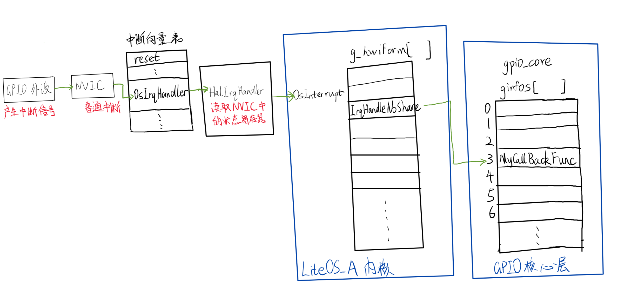
The interrupt of gpio peripheral will pass through the NVIC interrupt controller to trigger the ordinary interrupt of ARM, and the CPU will go to the OSIrqHandler of the interrupt vector table to execute:
The code of OSIrqHandler is in kernel/liteos_a/arch/arm/arm/src/los_dispatch.S. For the code of this part, please refer to the following blog:
Hongmeng research station is updated on January 28, 2022 (weharmony.github.io)
OsIrqHandler:
	......
    BLX     HalIrqHandler
	......
The job of HalIrqHandler is to read the NVIC register, get the interrupt number, and then call OsInterrupt() to execute the corresponding interrupt service routine.
VOID HalIrqHandler(VOID)
{
    UINT32 iar = GiccGetIar();
    UINT32 vector = iar & 0x3FFU;

    /*
     * invalid irq number, mainly the spurious interrupts 0x3ff,
     * valid irq ranges from 0~1019, we use OS_HWI_MAX_NUM to do
     * the checking.
     */
    if (vector >= OS_HWI_MAX_NUM) {
        return;
    }
    g_curIrqNum = vector;

    OsInterrupt(vector);
    GiccSetEoir(vector);
}
OsInterrupt():
//Trigger interrupt of kernel layer
VOID OsInterrupt(UINT32 intNum)
{
	......
    //In global array G_ Remove the interrupt service function from hwiform []
    hwiForm = (&g_hwiForm[intNum]);

        if (hwiForm->uwParam) {
            HWI_PROC_FUNC2 func = (HWI_PROC_FUNC2)hwiForm->pfnHook;
            if (func != NULL) {
                //Call interrupt service function
                UINTPTR *param = (UINTPTR *)(hwiForm->uwParam);
                func((INT32)(*param), (VOID *)(*(param + 1)));
            }
        } else {
            HWI_PROC_FUNC0 func = (HWI_PROC_FUNC0)hwiForm->pfnHook;
            if (func != NULL) {
                func();
            }
        }
	.......

}
IrqHandleNoShare() has been analyzed in the previous section, and it will eventually call mycallbackfunction() to execute our interrupt callback function.
3, Summary
ARM ordinary interrupt will cause cpu to execute a specific function in the interrupt vector table. In this function, it is necessary to determine which peripheral interrupt is, which is known by reading the register of NVIC.
Since the kernel is responsible for managing interrupts, the kernel implements the processing of external interrupts. In liteos_a, a global array is used to store all peripheral interrupt service functions.
The above is the common case of peripheral interrupt processing. For gpio interrupt, the intervention of gpio core layer is required. The gpio core layer also stores the callback functions of all gpio pins through a global array.
Why do I need gpio core? I think it's probably to facilitate the management of gpio. Take interrupts as an example. Different gpios have different interrupt handlers, but they all have some commonalities, that is, they need to clear the interrupt flag bit. gpio core puts these common processes in the unified NoShare function and creates an interrupt vector table to manage all interrupts.
In short, gpio core is a connecting link between the preceding and the following. The driver developers write the driver (such as gpio controller) according to the provisions of gpio core, and the upper application can pass gpio_if you use the driver correctly, as a driver developer, you need to be familiar with the core layer of gpio core and other types of peripherals, so as to develop the correct driver.