Virtual Link Topology
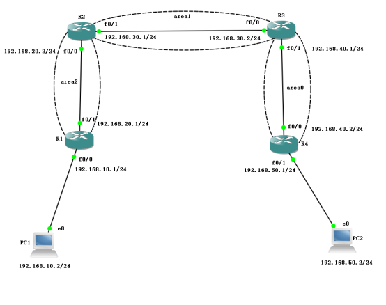
1. Service-side environment deployment
1. R1 router:
Configure the IP address information of each interface, configure the fixed IP address of the loop network card, and configure the OSPF protocol information.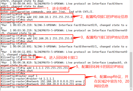
conf t
int f0/0
ip add 192.168.10.1 255.255.255.0
no shut
int f0/1
ip add 192.168.20.1 255.255.255.0
no shut
ex
int lo 0
ip add 1.1.1.1 255.255.255.255
no shut
ex
router ospf 1
router-id 1.1.1.1
network 192.168.10.0 0.0.0.255 area 2
network 192.168.20.0 0.0.0.255 area 2
2. R2 Router
Configure the IP address information of each interface, configure the fixed IP address of the loop network card, configure the OSPF protocol information, and create virtual links.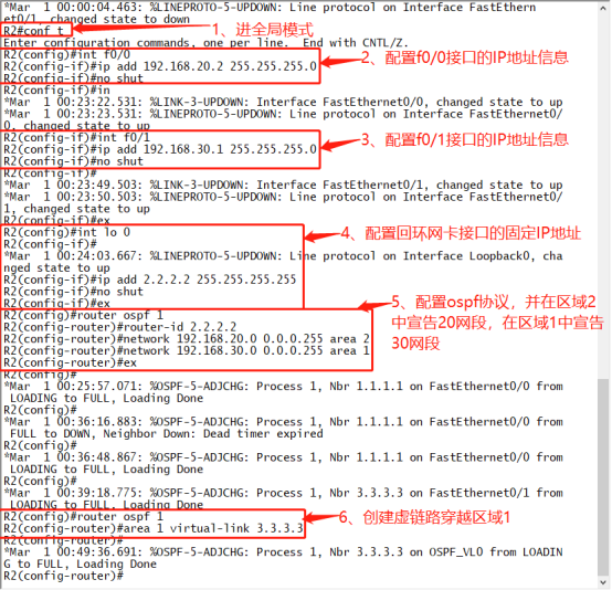
conf t
int f0/0
ip add 192.168.20.2 255.255.255.0
no shut
int f0/1
ip add 192.168.30.1 255.255.255.0
no shut
ex
int lo 0
ip add 2.2.2.2 255.255.255.255
no shut
ex
router ospf 1
router-id 2.2.2.2
network 192.168.20.0 0.0.0.255 area 2
network 192.168.30.0 0.0.0.255 area 1
ex
router ospf 1
area 1 virtual-link 3.3.3.3
3. R3 router:
Configure the IP address information of each interface, configure the fixed IP address of the loop network card, configure the OSPF protocol information, and create virtual links.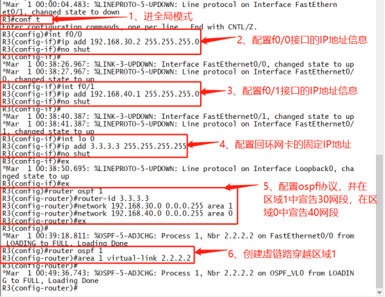
conf t
int f0/0
ip add 192.168.30.2 255.255.255.0
no shut
ex
int f0/1
ip add 192.168.40.1 255.255.255.0
no shut
int lo 0
ip add 3.3.3.3 255.255.255.255
no shut
ex
router ospf 1
router-id 3.3.3.3
network 192.168.30.0 0.0.0.255 area 1
network 192.168.40.0 0.0.0.255 area 0
ex
router ospf 1
area 1 virtual-link 2.2.2.2
4. R4 router:
Configure the IP address information of each interface, configure the fixed IP address of the loop network card, and configure the OSPF protocol information.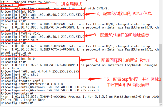
conf t
int f0/0
ip add 192.168.40.2 255.255.255.0
no shut
int f0/1
ip add 192.168.50.1 255.255.255.0
no shut
ex
int lo 0
ip add 4.4.4.4 255.255.255.255
no shut
ex
router ospf 1
router-id 4.4.4.4
network 192.168.40.0 0.0.0.255 area 0
network 192.168.50.0 0.0.0.255 area 0
II. Client Environment Deployment
1. PC1 Configuration IP Address and Gateway Information

2. PC2 Configuration IP Address and Gateway Information

3. Verify the Interoperability of the Whole Network
