I. principle of PID algorithm
In industrial applications, PID and its derivative algorithms are one of the most widely used algorithms and are well deserved universal algorithms. If you can skillfully master the design and implementation process of PID algorithm, it should be enough for ordinary R & D personnel to deal with general R & D problems. Among the control algorithms I have contacted, PID control algorithm is the simplest, The control algorithm that can best reflect the feedback idea can be described as a classic among the classics. Classical is not necessarily complex. Classical things are often simple and the simplest. Think about Newton's three laws of mechanics and Einstein's mass energy equation. How simple! Simple is not original, simple is not backward, simple to the extent of beauty. Let's first look at the general form of PID algorithm:
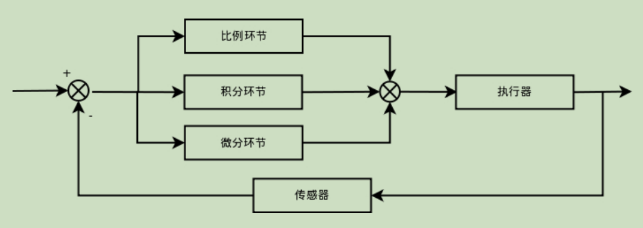
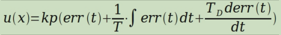
The process of PID is too simple to be simple. The controlled quantity is controlled by error signal, and the controller itself is the sum of proportional, integral and differential links. The control law of PID in continuous state is
Discretization of two PID algorithms
In the previous section, I discussed the basic form of PID algorithm and gave a brief description of the realization of its control process. Through the summary of the previous section, I can basically understand the process of PID control. In this section, we will continue with the previous section to supplement.
1. Explain the principle of feedback control. It is not difficult to see from the block diagram in the previous section that PID control is actually a control process of deviation;
2. If the deviation is 0, the proportional link will not work. Only when there is a deviation, the proportional link will work.
3. The integration link is mainly used to eliminate the static error. The so-called static error is the difference between the output value and the set value after the system is stable. The integration link is actually the process of deviation accumulation. The accumulated error is added to the original system to offset the static error caused by the system.
4., differential signals reflect the change rule of deviation signal, or change trend, and make advance adjustment according to the trend of deviation signal, thus increasing the rapidity of the system.
Assuming that the sampling interval is T, at time K T:
Deviation err (k) = Rin (k) - route (k);
The integration link is expressed in the form of addition, that is, err(K)+err(K+1) +;
The differential link is expressed in the form of slope, i.e. [err(K)-err(K-1)]/T;
Thus, the following PID discrete representation is formed
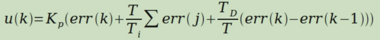
Namely

As for the specific expressions of Kp, Ki and Kd parameters, I think they can be easily introduced. Here, time is saved and will not be expressed in detail. In fact, so far, the basic discrete representation of PID has come out. At present, this expression belongs to position PID.
III. program sharing
#include "main.h"
#include "stdlib.h"

typedef struct PID {
	float SetPoint;
	float P;        //
	float I;        //
	float D;        //
	int LastError;
	int sumERROR;
} PID;

PID pp;
u16 PID_Cal(PID *pp,u16 adc1_now_val);
u16 dac_val=1230;
u16 adc1_now_val=0;
u16 adc1_next_val=0;
int main(void)
{

  pp.SetPoint=3000; pp.P=1.4;	pp.I=0.1;	pp.D=0.01;	pp.sumERROR=0; pp.LastError=0;
	NVIC_PriorityGroupConfig(NVIC_PriorityGroup_2); //Set NVIC interrupt packet 2: 2-bit preemption priority and 2-bit response priority
    uart_init(115200);
	delay_init();	    //Delay function initialization
	LED_Init();		  	//Initialize the hardware interface to the LED
	Adc_Init();
	Dac1_Init();
	TIM3_Int_Init(3999,7299);   //Set TIM3 timing time to 400ms
	DAC_SetChannel1Data(DAC_Align_12b_R,dac_val);  //Set the DAC's initial output value to 1230
	while(1)
	{
		LED0_GREEN=!LED0_GREEN;
    adc1_now_val=Get_Adc(1);          		//Gets the sampling value of ADC1 channel 1
		adc1_next_val=PID_Cal(&pp,adc1_now_val);
		adc1_next_val=adc1_next_val+adc1_now_val;
		DAC_SetChannel1Data(DAC_Align_12b_R,adc1_next_val);//12 bit right aligned data format to set DAC value
		printf("%d\r\n",adc1_now_val);
		delay_ms(500);	//Delay 500ms
	}
 }
 u16 PID_Cal(PID *pp,u16 adc1_now_val)
 {
	 int dERROR=0, ERROR=0,mid_pid_val=0;
	 ERROR=pp->SetPoint-adc1_now_val;//Current error for scale calculation
	 pp->sumERROR+=ERROR;            //Error sum for integral calculation
	 dERROR=ERROR-pp->LastError;     //Error deviation, for differential operation
	 pp->LastError=ERROR;
		 if(pp->sumERROR>600)
			 pp->sumERROR=600;
		 if(pp->sumERROR<-600)
			 pp->sumERROR=-600;
	 mid_pid_val=pp->P*ERROR+pp->I*pp->sumERROR+pp->D*dERROR;//Calculate PID value
	 if(mid_pid_val>200)
		 mid_pid_val=200;
	 else if(mid_pid_val<0)
		 mid_pid_val=0;
	 adc1_next_val=mid_pid_val;
	 return adc1_next_val;
 }