preface
Friends in this line know that when you really take a single chip microcomputer as a project, as a software writer, you must have more than one single chip microcomputer, or you must have the ability to start a new single chip microcomputer independently. The new here refers to what you have never been in contact with or unfamiliar with personally, not necessarily how new this single chip microcomputer is. Debugging a new single chip microcomputer often starts with the creation of the project. Here, I share the project creation and compilation of GD32F303 from scratch with MDK as the compilation software.
Environment construction
- 1. First of all, MDK is installed on your computer and has been cracked. The version doesn't require much. Just support C99. My MDK version is 5.26.
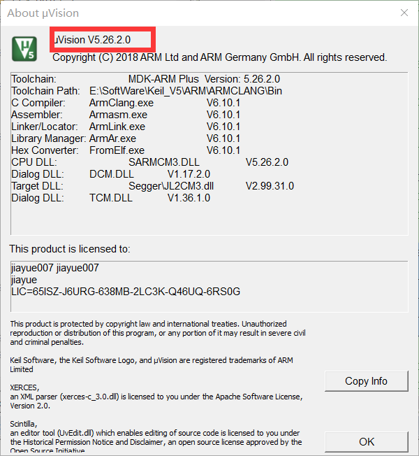
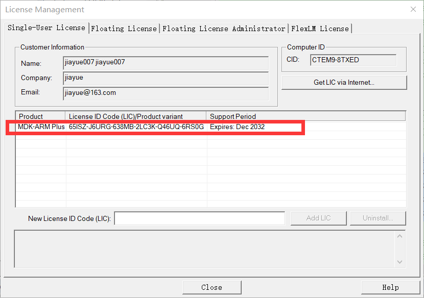
- 2. Then download and install the support package for GD32F303 under keil. Install it in your KEIL5 installation path.
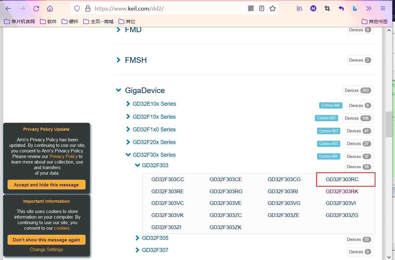
1) , entry Keil official website , select Supported Microcontrollers

2) . scroll the page to find the support package corresponding to the chip we use, and click gigadevice -- > gd32f30x series -- > gd32f303 -- > gd32f303rc in turn.
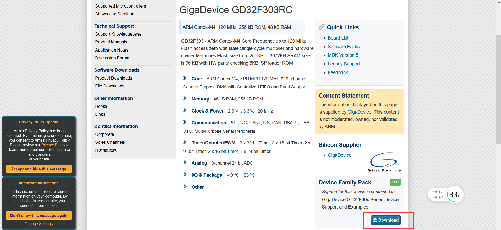
 3) . after entering, there will be a description of the chip. Click Download on the page.
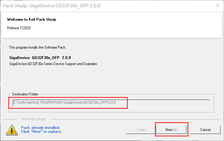
4) After finding the installation path of KEIL5, go all the way to NEXT and finally FINISH. I have installed it here. The page will be slightly different.
Project creation
-
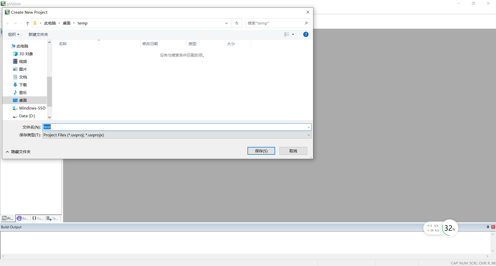
Open KEIL5 and select project -- > New uVision project. You will be asked to choose where to store the project, create a new folder and name the project, such as "test".
-
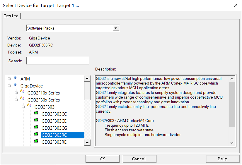
After that, you will be asked to choose the chip model. Here we choose GD32F303RC. (if there is no GigaDevice or GD32F303RC in the chip, check whether the installation path of your GD32F303 support package is under the installation path of KEIL5)
-
We don't need to Cancel the pop-up manage run time environment in the lower right corner.
-
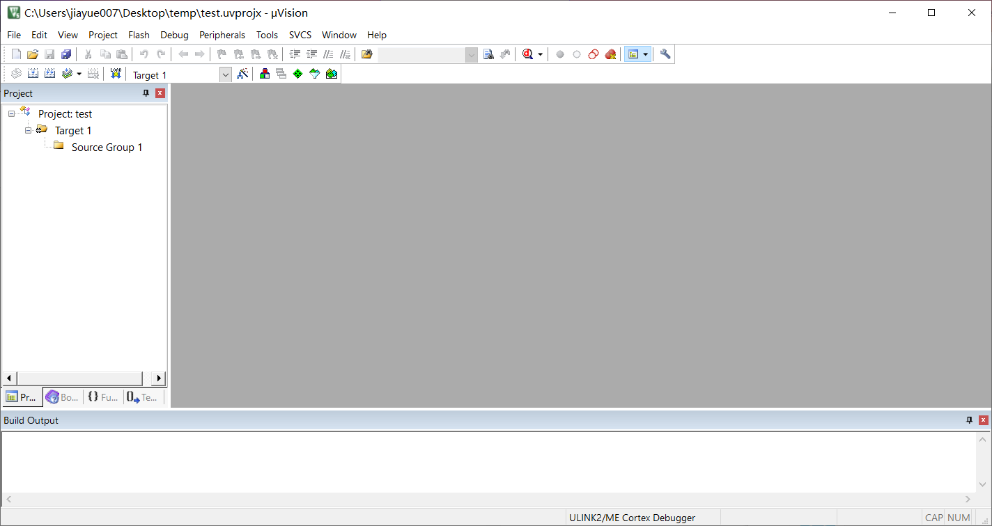
The interface is as follows: an empty GD32F303 keil5 project has been built:
File add
-
Due to the abundant peripheral resources of 32-bit single chip microcomputer, it is no longer developed with registers like 51. Generally, the standard library or even HAL library provided by the official is introduced for development. There are many miscellaneous files. Before adding the files, we first create multiple folders, as follows:
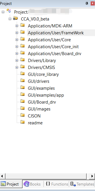
1) . Application/MDK-ARM is used to place project startup files. Such as sratup_gd32f303_hd.s
Application/User/FrameWork is used to place program framework files. For example, whether to use bare metal or state machine, time slice or RTOS.
Application/User/Core is used to place main.c and gd32f30x_it.c, the business logic between modules is mainly reflected in these two files.
Application/User/Core_init is used to place the file for configuring MCU peripheral resources. The initialization functions of peripherals such as AD and USART are placed here.
Application/User/Board_drv is used to place function files that implement some specific functions. Such as AD filter function, display function, etc.
2) Drivers/Library is used to place the standard library files provided by the official.
Drivers/CMSIS is used to place the lowest level header file officially provided, which contains the register definition and compilation environment configuration of the corresponding MCU.
3) Other documents are reserved for my own actual project. This part does not have to be the same as me. -
The project folder in the computer is as follows:
 1) Place the source files officially given to us in and Drivers.
GUI library should be used for GUI placement, which can be ignored here.
map places the. map file of the project compilation output, which is convenient to view the size of each code segment and the whole code and analyze problems.
MDK-ARM places. uvprojx files and startup files. Easy to open and adjust startup files.
 2) User corresponds to the file starting with Application in the project. The following documents are divided into the above categories.
TMT is the program framework file I used this time. It is essentially a time slice. It is also convenient for later maintenance. (there is no more expansion here. The source code is here Gitee I'd like to know if you are interested (it tastes like RTOS)
3. So far, both the file classification in keil project and the classification management of each source file under the computer have been handled.
Option configuration
-
Click the magic wand in the project to modify the default arm compiler. I like the V6 compiler. It's OK not to modify it by default.
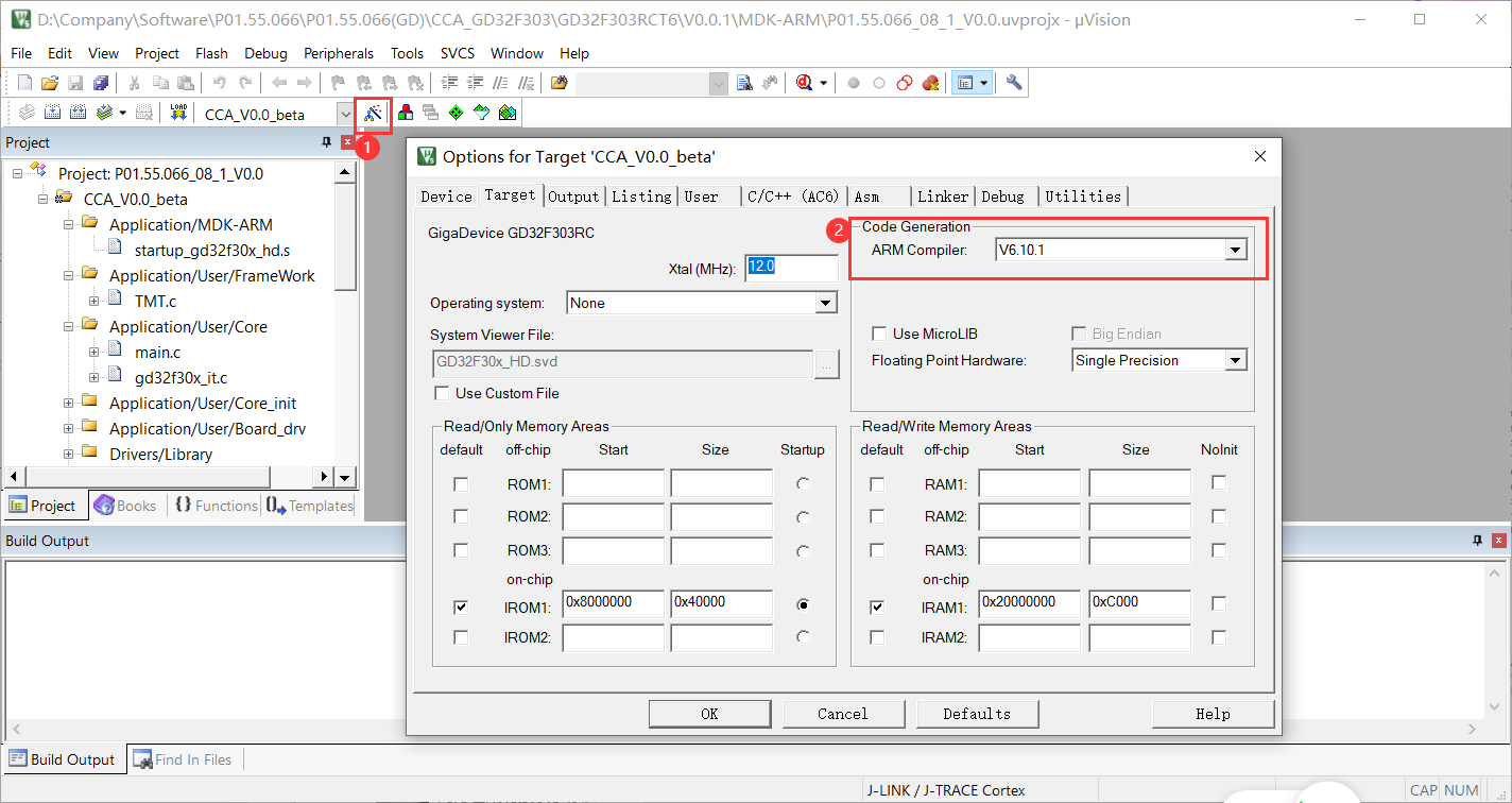
-
Check Browse Information in the OUTPUT option and modify the name, such as test. Here is to generate a series of files, in which we need the. hex file. Prepare for compilation and download.
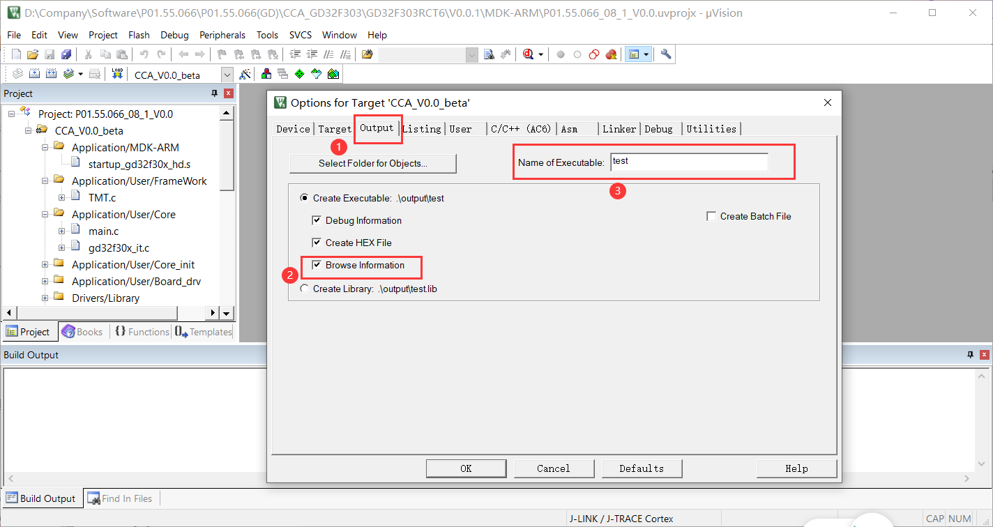
-
In C/C++(AC6), select the ··· button on the right of the line of Include Path, add each file path in the computer folder, check whether it is C99, and click OK after confirmation.
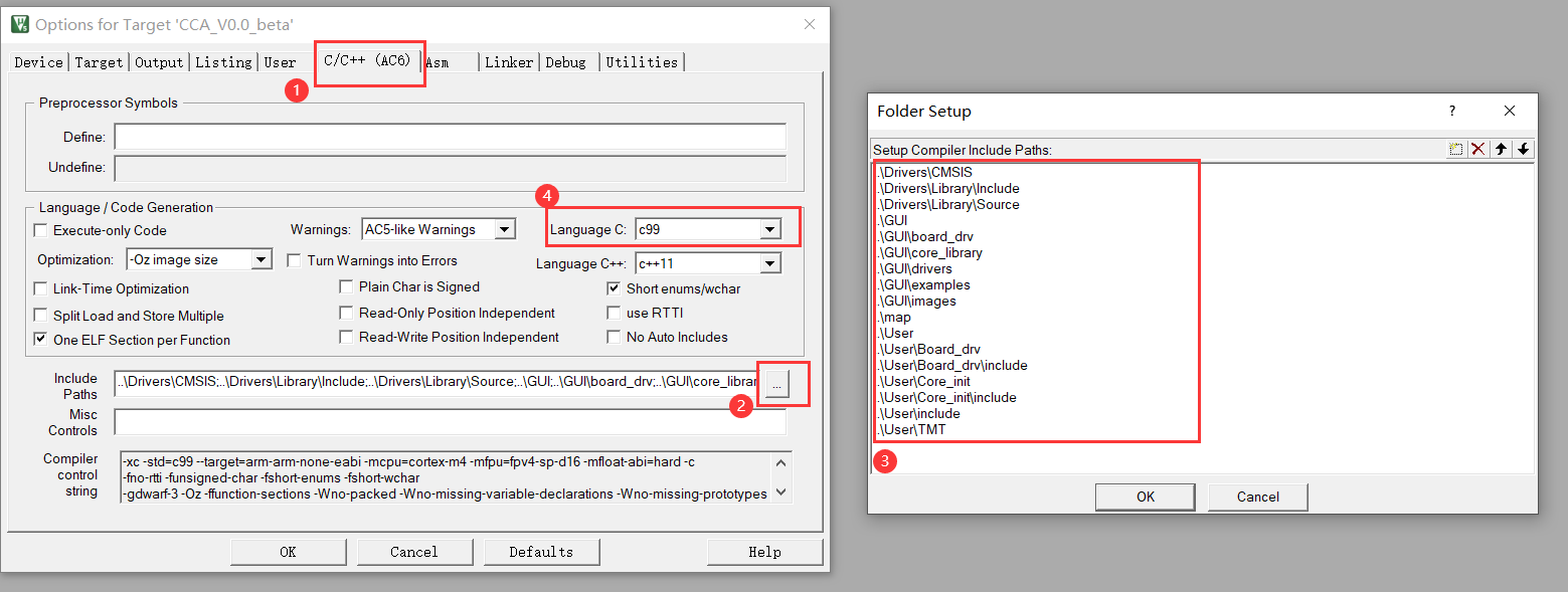
-
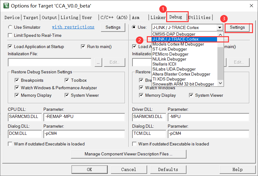
Select the download emulator to use in the Debug column. I use j-link. After selecting, click setting on the right.
-
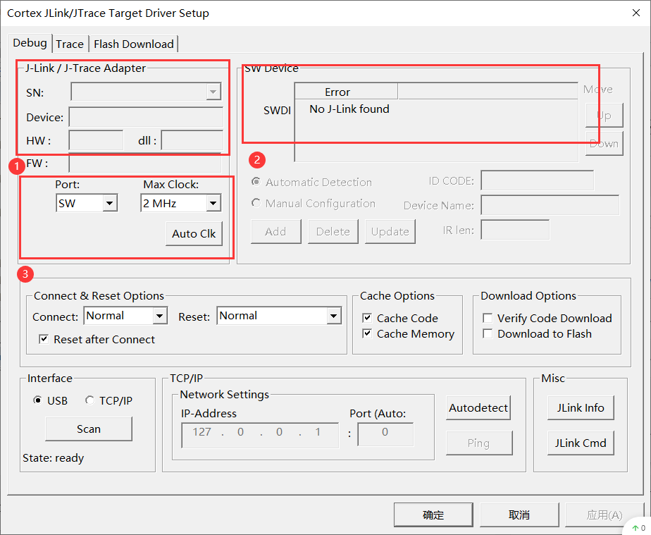
In the pop-up Debug column, after the computer is connected and J-Link is detected, the corresponding J-Link data and firmware version will be displayed at ① and ②. I didn't have J-Link around when I wrote this article, so I didn't have anything. ③ The J-Link download mode is selected, and the SW mode is selected, so that the download occupies the least IO port. As for the download speed, I generally choose 2MHz, which is related to the impedance of the PCB download line. It is too fast to detect J-Link and easy to fail in the download process.
-
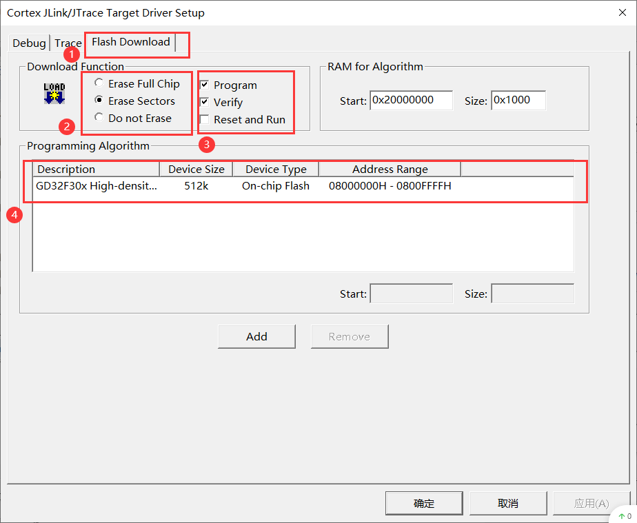
In the pop-up Flash Download column, select Erase Sectors instead of Erase Full Chip, because we are a debugger and erase the FLASH area involved in storing the code. If you erase the whole chip, some data you saved before will also be erased. ③ You can check Reset and Run, so that you can run your code immediately after downloading with the downloader. ④ It is used to check whether the actual model capacity of your chip corresponds to it. OK, OK.
Clock profile
- Systeminit() function in startup file
;/* reset Handler */
Reset_Handler   PROC
              EXPORT  Reset_Handler                     [WEAK]
              IMPORT  SystemInit
              IMPORT  __main
              LDR     R0, =SystemInit
              BLX     R0
              LDR     R0, =__main
              BX      R0
              ENDP
There is no more explanation here. We just look at R0. R0 is given SystemInit first, and then__ Main, really enter the main function. It means that every time the power on program runs systeminit() first, it will enter the main function.
- Systeminit() function
void SystemInit (void)
{
  /* FPU settings */
#if (__FPU_PRESENT == 1) && (__FPU_USED == 1)
    SCB->CPACR |= ((3UL << 10*2)|(3UL << 11*2));  /* set CP10 and CP11 Full Access */
#endif
    /* reset the RCU clock configuration to the default reset state */
    /* Set IRC8MEN bit */
    RCU_CTL |= RCU_CTL_IRC8MEN;

    RCU_MODIFY

    /* Reset CFG0 and CFG1 registers */
    RCU_CFG0 = 0x00000000U;
    RCU_CFG1 = 0x00000000U;

#if (defined(GD32F30X_HD) || defined(GD32F30X_XD))
    /* reset HXTALEN, CKMEN and PLLEN bits */
    RCU_CTL &= ~(RCU_CTL_PLLEN | RCU_CTL_CKMEN | RCU_CTL_HXTALEN);
    /* disable all interrupts */
    RCU_INT = 0x009f0000U;
#elif defined(GD32F30X_CL)
    /* Reset HXTALEN, CKMEN, PLLEN, PLL1EN and PLL2EN bits */
    RCU_CTL &= ~(RCU_CTL_PLLEN |RCU_CTL_PLL1EN | RCU_CTL_PLL2EN | RCU_CTL_CKMEN | RCU_CTL_HXTALEN);
    /* disable all interrupts */
    RCU_INT = 0x00ff0000U;
#endif
    /* reset HXTALBPS bit */
    RCU_CTL &= ~(RCU_CTL_HXTALBPS);

    /* configure the system clock source, PLL Multiplier, AHB/APBx prescalers and Flash settings */
    system_clock_config();
}
Write a lot, but the key is two. system_clock_config(); And #if (defined (gd32f30x_hd) | defined (gd32f30x_xd)), the former must be the configuration of the clock, and the latter is the definition of the chip capacity.
- GD32F30X_HD,GD32F30X_XD and GD32F30X_CL

/* define GD32F30x */
#if !defined (GD32F30X_HD) && !defined (GD32F30X_XD) && !defined (GD32F30X_CL)
  /* #define GD32F30X_HD */
  /* #define GD32F30X_XD */
  /* #define GD32F30X_CL */
#endif /* define GD32F30x */
The above codes are undefined in gd32f30x.h by default. We judge whether to define one of them according to the actual capacity.
- system_clock_config()
/* select a system clock by uncommenting the following line */
/* use IRC8M */
//#define __SYSTEM_CLOCK_IRC8M                    (uint32_t)(__IRC8M)
//#define __SYSTEM_CLOCK_48M_PLL_IRC8M            (uint32_t)(48000000)
//#define __SYSTEM_CLOCK_72M_PLL_IRC8M            (uint32_t)(72000000)
//#define __SYSTEM_CLOCK_108M_PLL_IRC8M           (uint32_t)(108000000)
//#define __SYSTEM_CLOCK_120M_PLL_IRC8M           (uint32_t)(120000000)

/* use HXTAL(XD series CK_HXTAL = 8M, CL series CK_HXTAL = 25M) */
//#define __SYSTEM_CLOCK_HXTAL                    (uint32_t)(__HXTAL)
//#define __SYSTEM_CLOCK_48M_PLL_HXTAL            (uint32_t)(48000000)
//#define __SYSTEM_CLOCK_72M_PLL_HXTAL            (uint32_t)(72000000)
#define __SYSTEM_CLOCK_108M_PLL_HXTAL           (uint32_t)(108000000)
//#define __SYSTEM_CLOCK_120M_PLL_HXTAL           (uint32_t)(120000000)

static void system_clock_config(void)
{
#ifdef __SYSTEM_CLOCK_IRC8M
    system_clock_8m_irc8m();
#elif defined (__SYSTEM_CLOCK_48M_PLL_IRC8M)
    system_clock_48m_irc8m();
#elif defined (__SYSTEM_CLOCK_72M_PLL_IRC8M)
    system_clock_72m_irc8m();
#elif defined (__SYSTEM_CLOCK_108M_PLL_IRC8M)
    system_clock_108m_irc8m();
#elif defined (__SYSTEM_CLOCK_120M_PLL_IRC8M)
    system_clock_120m_irc8m();

#elif defined (__SYSTEM_CLOCK_HXTAL)
    system_clock_hxtal();
#elif defined (__SYSTEM_CLOCK_48M_PLL_HXTAL)
    system_clock_48m_hxtal();
#elif defined (__SYSTEM_CLOCK_72M_PLL_HXTAL)
    system_clock_72m_hxtal();
#elif defined (__SYSTEM_CLOCK_108M_PLL_HXTAL)
    system_clock_108m_hxtal();
#elif defined (__SYSTEM_CLOCK_120M_PLL_HXTAL)
    system_clock_120m_hxtal();
#endif /* __SYSTEM_CLOCK_IRC8M */
}
system_ clock_ The config() function and systeminit() function are in the same. c file. Here is mainly to configure the system clock source. I select 108M after external crystal oscillator input + PLL frequency doubling as the system clock.
Engineering compilation
- Create and modify main.h
#ifndef MAIN_H
#define MAIN_H

#define _nop_() __asm("nop");
#define NOP _nop_();_nop_();_nop_();_nop_();_nop_();_nop_();_nop_();_nop_();\
			_nop_();_nop_();_nop_();_nop_();_nop_();_nop_();_nop_();_nop_();

/* include all headfiles you created */
#include "TMT.h"
#include "task.h"
#include "peripheral.h"
#include "gpio.h"

#endif /* MAIN_H */
- Create and modify periodic. C and periodic. H
#include "gd32f30x.h"
#include "peripheral.h"

void SystemTick_Init(void)
{
   /* setup systick timer for 1000Hz interrupts */
   if (SysTick_Config(SystemCoreClock / 1000U)){
       /* capture error */
       while (1){
       }
   }

	/* Set Interrupt Group Priority */
	nvic_priority_group_set(NVIC_PRIGROUP_PRE4_SUB0);
}

void SystemClock_Reconfig(void)
{
	/* Enable all peripherals clocks you need*/
	rcu_periph_clock_enable(RCU_GPIOA);
	rcu_periph_clock_enable(RCU_GPIOB);
	rcu_periph_clock_enable(RCU_GPIOC);
	rcu_periph_clock_enable(RCU_GPIOD);
}
1ms tick clock and priority group configuration of all interrupts.
#ifndef peripheral_H
#define peripheral_H

#include <stdint.h>

/* SystemTick Init */
void SystemTick_Init(void);
/* Initializes the CPU, AHB and APB busses clocks.Enable all peripherals clocks you need. */
void SystemClock_Reconfig(void);

#endif /* peripheral_H */
- Create and modify gpio.c and gpio.h
#include "gd32f30x.h"
#include "gpio.h"

void GPIO_Init(void)
{
	/* Use SW download instead of JTAG download, and the pin is used for other functions */
	gpio_pin_remap_config(GPIO_SWJ_SWDPENABLE_REMAP, ENABLE);

	/* demo board LED I/O */
 	gpio_init(GPIOC, GPIO_MODE_OUT_PP, GPIO_OSPEED_50MHZ, GPIO_PIN_11);
	gpio_bit_reset(GPIOC,GPIO_PIN_11);
}
#ifndef gpio_H
#define gpio_H

#include "main.h"
#include <stdint.h>

void GPIO_Init(void);

#endif
- Create and modify task.c and task.h
#include "gd32f30x.h"
#include "task.h"

void TASK_IO_REVERSE(void)
{
	static uint32_t countx=0;
	if(countx<65535)	countx++;

	if(countx%2==0)
	{
		gpio_bit_reset(GPIOC,GPIO_PIN_11);
	}
	else
	{
		gpio_bit_set(GPIOC,GPIO_PIN_11);
	}
}
#ifndef task_H
#define task_H

#include "main.h"
#include <stdint.h>

void TASK_IO_REVERSE(void);

#endif
- Create and modify gd32f30x_it.c
#include "gd32f30x_it.h"
#include "main.h"

void SysTick_Handler(void)
{
	TMT.Tick();
}
- Create and modify main.c
#include "gd32f30x.h"
#include "gd32f30x_libopt.h"
#include "main.h"

int main(void)
{
	SystemTick_Init();
	SystemClock_Reconfig();
	GPIO_Init();
	TMT_Init();
	TMT.Create(TASK_IO_REVERSE,500);
	while(1)
	{
		TMT.Run();
	}
}
- Here's a general explanation,
SystemTick_Init() ,SystemClock_Reconfig() and GPIO_Init() is the initialization configuration of MCU peripherals, which is placed in the application / user / core of the project_ Inside init.
Because the time slice framework is used, each task writes a specific implementation function separately, which is placed in Task.c and in the application / user / board of the project_ Inside the DRV.
TASK_ IO_ The function reverse() is executed every 500ms. The intention here is also very simple, that is, to flip the IO of PC11 every 0.5 seconds.
summary
So far, a keil project of GD32F303 created from scratch has been completed. Later, we can use this as a template to write our code. The final compilation and debugging results will not be shown in the figure, because there is nothing to look at. Here, only a few key points that need to be modified are shown to avoid the unsuccessful creation of the project. Finally, I wish you all a Happy Mid Autumn Festival and less hair loss, ha ha ha.
!!! This article is the original release, copy or reprint of Huanxi 6666 in CSDN. Please indicate the source:)!!!