About PIO(Programmed I/O) programming in Pico of raspberry pie, four articles have been written earlier:
former WS2812 lantern program It feels like a heavenly book. I can't understand it at all. Now I can uncover its mysterious veil.
import machine
import utime
import array
import rp2

@rp2.asm_pio(sideset_init=rp2.PIO.OUT_LOW, out_shiftdir=rp2.PIO.SHIFT_LEFT,
             autopull=True, pull_thresh=24)
def ws2812():
    T1 = 2
    T2 = 5
    T3 = 3
    wrap_target()
    label("bitloop")
    out(x, 1)               .side(0)    [T3 - 1]
    jmp(not_x, "do_zero")   .side(1)    [T1 - 1]
    jmp("bitloop")          .side(1)    [T2 - 1]
    label("do_zero")
    nop()                   .side(0)    [T2 - 1]
    wrap()


# Establish the state machine and set the number of output pins
sm = rp2.StateMachine(0, ws2812, freq=8_000_000, sideset_base=machine.Pin(15))
sm.active(1)

NUM_LEDS = 30
ar = array.array("I", [0 for _ in range(NUM_LEDS)])

while True:
    for j in range(NUM_LEDS):
        (r, g, b) = (0, 0, 0)
        if(j%3 == 0): r = 11
        if(j%3 == 1): g = 11
        if(j%3 == 2): b = 11
        ar[j] = g << 16 | r << 8 | b
    sm.put(ar, 8)
    utime.sleep_ms(20)
In order to study the assembly code of pioasm program, I simplified the main program and only let 30 lights display red, green and blue in turn.
First understand the special signal mechanism of WS2812, which is different from the usual way of high potential being 1 and low potential being 0. Its protocol represents 0 and 1 according to the duration of high and low potential, as shown in the figure below:
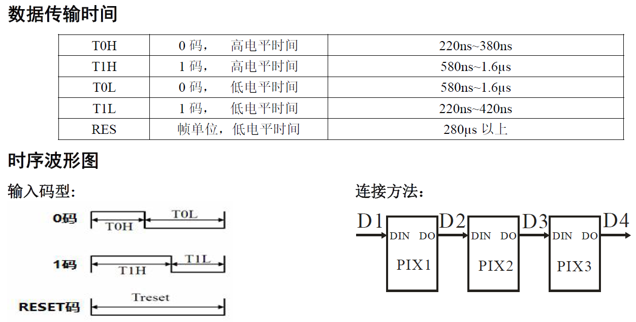
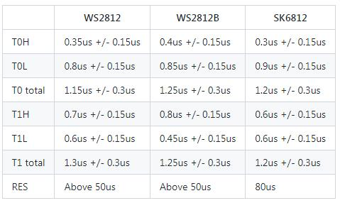
If the high level duration is less than the low level duration, it indicates 0; Long duration of low level indicates 1. The duration also has a strict range, in microseconds. The Chinese Manual of WS2812B I found is a little different from that in foreign forums.
The frequency of pioasm state machine in the main program is 8M Hz, so the assembly instruction cycle is 1/8000000=0.125 us (microseconds). See that T1, T2 and T3 in the code are 2, 5 and 3 respectively, which corresponds to 0.25 us, 0.625 us and 0.375 us.
The meanings of these three times are shown in the following figure:
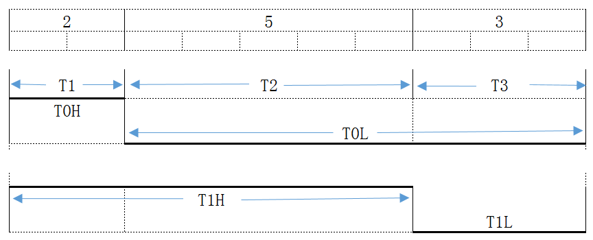
T0L=T2+T3=1.0us, within the index range (0.58us ~ 1.6us), T1H=T1+T2=0.875, also within the index range (0.58us ~ 1.6us). It is always high potential in T1 period and low potential in T3 period. The potential in T2 period corresponds to the represented data: 0 or 1.
Now you can look at the assembly code, out_shiftdir=rp2.PIO.SHIFT_LEFT indicates that the data in OSR is shifted to the left, autopull=True, pull_thresh=24 means that the data is automatically retrieved from the OSR, and only 24 bits are retrieved (corresponding to the RGB value).
out(x, 1) means to remove 1-bit data from the OSR and put it into the X register. The following. side(0) sets the low potential and [T3-1] fills the T3 instruction cycle.
jmp(not_x, "do_zero") means to jump to do when X is 0_ Zero position code, when X is not 0, continue to execute the following statement.
When x is not 0, execute the sentence jmp("bitloop") and prepare to jump to the beginning of the program. Before the jump, take the completion side(1). Because x is not 0, the logic of side(1) is correct, and the total delay time is T2.
When x is 0, execute the nop().side(0) instruction, and the total delay time is also T2.
The main program initializes an array with array.array("I", list). The int type of modern computers is generally a 4-byte (32-bit) integer used to set the RGB value (24 bits) of the light group.
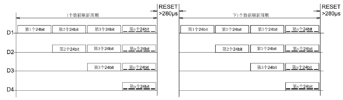
sm.put(ar, 8) is used to quickly send all data in the array to the FIFO queue of the state machine. The second parameter 8 indicates that the data is shifted to the left by 8 bits and then sent to the FIFO. In the refresh cycle of a group of colored lights, the 24 bit GRB values (note that the order is green, red and blue) should be sent out quickly one by one. If there is a slight delay, it will be considered as the refresh cycle of the next group of colored lights.
I looked at the specification parameters of WS2812B. When T1=T2=T3=0.375, it also meets the requirements of various indicators and should also work. Therefore, I simplified the program. The state machine still works at the frequency of 8M Hz and has no problem at all:
@rp2.asm_pio(sideset_init=rp2.PIO.OUT_LOW, out_shiftdir=rp2.PIO.SHIFT_LEFT,
             autopull=True, pull_thresh=24)
def ws2812():
    label("bitloop")
    out(x, 1)               .side(0)    [2]
    jmp(not_x, "do_zero")   .side(1)    [2]
    jmp("bitloop")          .side(1)    [2]
    label("do_zero")
    nop()                   .side(0)    [2]
If the state machine is operated at 2.7M frequency, the delay parameters can also be saved:
@rp2.asm_pio(sideset_init=rp2.PIO.OUT_LOW, out_shiftdir=rp2.PIO.SHIFT_LEFT,
             autopull=True, pull_thresh=24)
def ws2812():
    label("bitloop")
    out(x, 1)               .side(0)
    jmp(not_x, "do_zero")   .side(1)
    jmp("bitloop")          .side(1)
    label("do_zero")
    nop()                   .side(0)

sm = rp2.StateMachine(0, ws2812, freq=2_700_000, sideset_base=machine.Pin(15))
sm.active(1)
The modified code works normally on my WS2812B, but I don't know whether it works normally on the old 2812.