Small experiment catalogue
Raspberry pie science experiment
001 turn on the first LED
002 light up the LED lamp group
003_ Switch control LED light
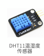
004_ Obtain temperature and humidity
Tip: after writing the article, the directory can be generated automatically. For how to generate it, please refer to the help document on the right
preface
In this experiment, we will contact with the clock signal and receive the high and low levels. Byte conversion
Tip: the following is the main content of this article. The following cases can be used for reference
1, Experimental components
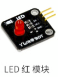
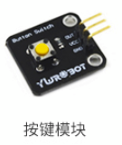
1 Experimental components
2 connected GPIO pin
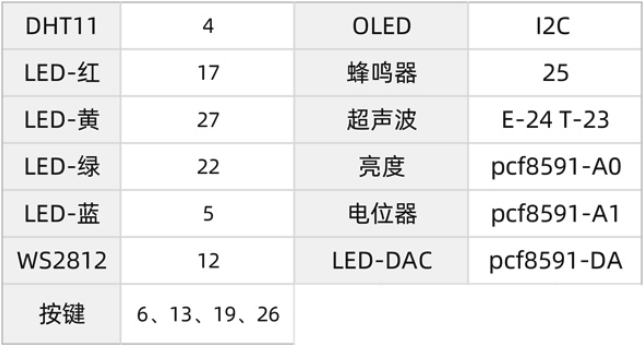
Pins used: 4, 17, 27, 19
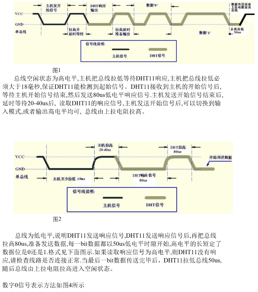
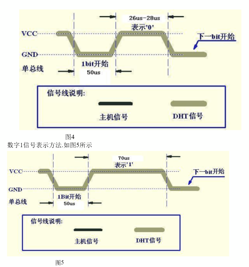
2, Process of communication between DHT11 and MCU or raspberry pie
Because python cannot control the accuracy of us clock, it will be unable to obtain or incomplete to obtain the signal when actually receiving. But the basic principle is shown in the figure below.
3, Code part
The open source project on github is cited here: https://github.com/szazo/DHT11_Python
1. Actual working code of DHT11
# -*- coding: utf-8 -*-
"""
#This is a class of DHT11, which will complete the initialization of the sensor, obtain the value, convert the value to hexadecimal and return it. This article refers to: https://github.com/szazo/DHT11_Python

version = '0.0.1'
make day=2022-01-26
"""
__docformat__ = "restructuredtext en"

__all__ = []

__license__ = "MIT license"

import time

import RPi.GPIO as GPIO
import RPi


# Define a display class for display and output
class DHT11Result:
    'DHT11 Return from DHT11.read()Value read in'
    ERR_NO_ERROR = 0
    ERR_MISSING_DATA = 1
    ERR_CRC = 2
    error_code = ERR_NO_ERROR
    temperature = -1
    humidity = -1

    def __init__(self, error_code, temperature, humidity):
        self.error_code = error_code
        self.temperature = temperature
        self.humidity = humidity

    def is_valid(self):
        return self.error_code == DHT11Result.ERR_NO_ERROR


# Class that defines probe initialization and acquisition
class DHT11:
    __pin = 0 #Define the value of Pin

    def __init__(self, pin):
        self.__pin = pin

    def __send_and_sleep(self, output, sleep):
        '''
        Set the transmission level value and sleep time
        :param output: Level value
        :param sleep: Dormancy time
        :return:
        '''
        GPIO.output(self.__pin, output)
        time.sleep(sleep)

    def __collect_input(self):
        '''
         This part completes the collection of input data
        '''
        unchanged_count = 0
        max_unchanged_count = 100

        last=-1
        data=[]
        while True:
            curent=GPIO.input(self.__pin)
            data.append(curent)
            if last != curent:
                unchanged_count=0
                last=curent

            else:
                unchanged_count+=1
                if unchanged_count>max_unchanged_count:
                    break

        return data

    def __parse_data_pull_up_lengths(self, data):
        '''
         This part completes the preliminary processing of the data
        '''
        STATE_INIT_PULL_DOWN = 1
        STATE_INIT_PULL_UP = 2
        STATE_DATA_FIRST_PULL_DOWN = 3
        STATE_DATA_PULL_UP = 4
        STATE_DATA_PULL_DOWN = 5

        state = STATE_INIT_PULL_DOWN

        lengths = []  # will contain the lengths of data pull up periods
        current_length = 0  # will contain the length of the previous period

        for i in range(len(data)):

            current = data[i]
            current_length += 1
            print(f"id:{i},value:{current},state:{state}")
            if state == STATE_INIT_PULL_DOWN:
                if current == RPi.GPIO.LOW:
                    # ok, we got the initial pull down
                    state = STATE_INIT_PULL_UP
                    continue
                else:
                    continue
            if state == STATE_INIT_PULL_UP:
                if current == RPi.GPIO.HIGH:
                    # ok, we got the initial pull up
                    state = STATE_DATA_FIRST_PULL_DOWN
                    continue
                else:
                    continue
            if state == STATE_DATA_FIRST_PULL_DOWN:
                if current == RPi.GPIO.LOW:
                    # we have the initial pull down, the next will be the data pull up
                    state = STATE_DATA_PULL_UP
                    continue
                else:
                    continue
            if state == STATE_DATA_PULL_UP:
                if current == RPi.GPIO.HIGH:
                    # data pulled up, the length of this pull up will determine whether it is 0 or 1
                    current_length = 0
                    state = STATE_DATA_PULL_DOWN
                    continue
                else:
                    continue
            if state == STATE_DATA_PULL_DOWN:
                if current == RPi.GPIO.LOW:
                    # pulled down, we store the length of the previous pull up period
                    lengths.append(current_length)
                    state = STATE_DATA_PULL_UP
                    continue
                else:
                    continue

        return lengths

    def __calculate_bits(self, pull_up_lengths):
        '''
         This part completes the shaping of the data
        '''
        # find shortest and longest period
        shortest_pull_up = 1000
        longest_pull_up = 0

        for i in range(0, len(pull_up_lengths)):
            length = pull_up_lengths[i]

            if length < shortest_pull_up:
                shortest_pull_up = length
            if length > longest_pull_up:
                longest_pull_up = length

        # use the halfway to determine whether the period it is long or short
        halfway = shortest_pull_up + (longest_pull_up - shortest_pull_up) / 2

        bits = []

        for i in range(0, len(pull_up_lengths)):
            bit = False
            if pull_up_lengths[i] > halfway:
                bit = True
            bits.append(bit)

        return bits

    def __bits_to_bytes(self, bits):
        '''
         bit turn bytes
        '''
        the_bytes = []
        byte = 0

        for i in range(0, len(bits)):
            print(f"left before:{byte}")
            byte = byte << 1
            print(f"left after:{byte}")
            if (bits[i]):
                byte = byte | 1
            else:
                byte = byte | 0
            if ((i + 1) % 8 == 0):
                the_bytes.append(byte)
                byte = 0
        print(f"the_bytes:{the_bytes}")
        return the_bytes

    def __calculate_checksum(self, the_bytes):
        return the_bytes[0] + the_bytes[1] + the_bytes[2] + the_bytes[3] & 255

    def read(self):
       '''
         Read data
        '''
        RPi.GPIO.setup(self.__pin, RPi.GPIO.OUT)

        # send initial high
        self.__send_and_sleep(RPi.GPIO.HIGH, 0.05)

        # pull down to low
        self.__send_and_sleep(RPi.GPIO.LOW, 0.02)

        # change to input using pull up
        RPi.GPIO.setup(self.__pin, RPi.GPIO.IN, RPi.GPIO.PUD_UP)

        # collect data into an array
        data = self.__collect_input()

        # parse lengths of all data pull up periods
        pull_up_lengths = self.__parse_data_pull_up_lengths(data)

        # if bit count mismatch, return error (4 byte data + 1 byte checksum)
        if len(pull_up_lengths) != 40:
            return DHT11Result(DHT11Result.ERR_MISSING_DATA, 0, 0)

        # calculate bits from lengths of the pull up periods
        bits = self.__calculate_bits(pull_up_lengths)

        # we have the bits, calculate bytes
        the_bytes = self.__bits_to_bytes(bits)

        # calculate checksum and check
        checksum = self.__calculate_checksum(the_bytes)
        if the_bytes[4] != checksum:
            return DHT11Result(DHT11Result.ERR_CRC, 0, 0)

        # ok, we have valid data

        # The meaning of the return sensor values
        # the_bytes[0]: humidity int
        # the_bytes[1]: humidity decimal
        # the_bytes[2]: temperature int
        # the_bytes[3]: temperature decimal

        temperature = the_bytes[2] + float(the_bytes[3]) / 10
        humidity = the_bytes[0] + float(the_bytes[1]) / 10

        return DHT11Result(DHT11Result.ERR_NO_ERROR, temperature, humidity)
2 outer calling code
# -*- coding: utf-8 -*-
"""
#This experiment was completed using DHT11 to read temperature and relative humidity
author = "Derek Tian"
version = '0.0.1'
make day=2022-01-25
"""
__docformat__ = "restructuredtext en"
__all__ = []
__license__ = "MIT license"
import time
import RPi.GPIO as GPIO
import DHT11 as dht11
import time
import datetime
# initialize GPIO
GPIO.setwarnings(True)
GPIO.setmode(GPIO.BCM)
# read data using pin 14
instance = dht11.DHT11(pin=4)
try:
while True:
result = instance.read()
if result.is_valid():
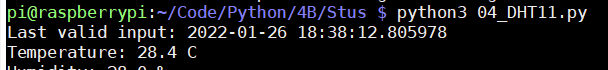
print("Last valid input: " + str(datetime.datetime.now()))
print("Temperature: %-3.1f C" % result.temperature)
print("Humidity: %-3.1f %%" % result.humidity)
time.sleep(6)
except KeyboardInterrupt:
print("Cleanup")
GPIO.cleanup()
4, Code analysis
1) In the main function:
RPI used here GPIO library to directly operate GPIO
import RPi.GPIO as GPIO
Set the BCM mode to operate GPIO, set the pin of DHT11 connection to 4, and initialize the working class of DHT11
GPIO.setwarnings(True)
GPIO.setmode(GPIO.BCM)
# read data using pin 14
instance = dht11.DHT11(pin=4)
Use a loop to get the value:
 while True:
        result = instance.read()
        if result.is_valid():
            print("Last valid input: " + str(datetime.datetime.now()))

            print("Temperature: %-3.1f C" % result.temperature)
            print("Humidity: %-3.1f %%" % result.humidity)
2) For dth11 Analysis of PY
(1) The function of transmitting signal is defined, and the sleep time is also defined here (this is the key, because it is the digital way of using software to simulate PWM). Because it needs to be called many times, it is abstracted as an independent function
 def __send_and_sleep(self, output, sleep):
        GPIO.output(self.__pin, output)
        time.sleep(sleep)
(2)__ collect_ The input() function receives the collected value
 def __collect_input(self):
        '''
         This part completes the collection of input data
        '''
        unchanged_count = 0
        max_unchanged_count = 100

        last=-1
        data=[]
        while True:
            curent=GPIO.input(self.__pin)

            data.append(curent)
            if last != curent:
                unchanged_count=0
                last=curent

            else:
                unchanged_count+=1
                if unchanged_count>max_unchanged_count:
                    break

        return data
Receive the signal through the cycle, collect the digital value, and set the maximum number of reading failures to 100. The collected digital signal is 0 or 1
You can print and display it by adding print
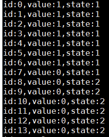
 (3)__ parse_ data_ pull_ up_ The length function completes the sorting of the types of original data collection
The key of the program is to define five states
        STATE_INIT_PULL_DOWN = 1 #Pre low level before transmission
        STATE_INIT_PULL_UP = 2  #The pre high level before transmission, which will tell the host to prepare for reception
        STATE_DATA_FIRST_PULL_DOWN = 3  # Send low level flag data ready to send
        STATE_DATA_PULL_UP = 4  #send data
        STATE_DATA_PULL_DOWN = 5  #End of data transmission
Through the cyclic processing of the received data packet, pick out the effective data frame for storage. The following is the processing output for each bit value:
When the data state changes to "STATE_DATA_PULL_UP" and the new bit is high, it will be initialized
 if state == STATE_DATA_PULL_UP:
                if current == RPi.GPIO.HIGH:
                    # data pulled up, the length of this pull up will determine whether it is 0 or 1
                    current_length = 0
                    state = STATE_DATA_PULL_DOWN
                    continue
                else:
                    continue
When the data status is "STATE_DATA_PULL_DOWN" and the new bit is a low-level value, write the value of count into the list
            if state == STATE_DATA_PULL_DOWN:
                if current == RPi.GPIO.LOW:
                    # pulled down, we store the length of the previous pull up period
                    lengths.append(current_length)
                    state = STATE_DATA_PULL_UP
                    continue
                else:
                    continue
Final returned value:
 (4)__ calculate_bits function completes the work of changing the value from count value to binary value. Here, the author adopts the way of intermediate value to judge.
Set the initial upper and lower boundaries, 01000 Since the maximum received byte effective bit cannot exceed 1000, it is set to 1000 here (because it is wasteful)
        shortest_pull_up = 1000
        longest_pull_up = 0
By finding the upper and lower boundaries, the intermediate value is calculated
 for i in range(0, len(pull_up_lengths)):
            length = pull_up_lengths[i]
            print(f"length:{length}|shortest_pull_up:{shortest_pull_up}|longest_pull_up:{longest_pull_up}")
            if length < shortest_pull_up:
                shortest_pull_up = length
            if length > longest_pull_up:
                longest_pull_up = length

        # use the halfway to determine whether the period it is long or short
        halfway = shortest_pull_up + (longest_pull_up - shortest_pull_up) / 2

Generate binary list according to intermediate value judgment
 for i in range(0, len(pull_up_lengths)):
            bit = False
            if pull_up_lengths[i] > halfway:
                bit = True
            bits.append(bit)

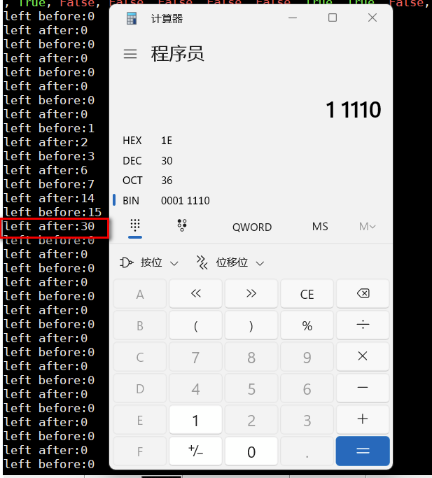
(5)__ bits_to_bytes obtains the collected value by bit calculation:
Here, the author completes the conversion from binary to decimal by shifting the bit bit to the left. When the bit bit is continuously shifted to the left to the 8th bit, the value will be a hexadecimal value.
 for i in range(0, len(bits)):
            print(f"left before:{byte}")
            byte = byte << 1
            print(f"left after:{byte}")
            if (bits[i]):
                byte = byte | 1
            else:
                byte = byte | 0
            if ((i + 1) % 8 == 0):
                the_bytes.append(byte)
 (6)__ calculate_checksum writes the generated 4-bit value into an array, which is not discussed here.
Read process of red()
In function initialization, the first step is to set the working direction of PIN pin: (output, input). Here, it is set as output, which is used to activate DHT11 module
RPi.GPIO.setup(self.__pin, RPi.GPIO.OUT)
"Call"__ send_ and_ "Sleep" function to control the pin
Output a high level and sleep for 0.05 seconds to activate DHT11 module
self.__send_and_sleep(RPi.GPIO.HIGH, 0.05)
Output a low level and sleep for 0.02 seconds, ready to receive the output value of DHT11 module
self.__send_and_sleep(RPi.GPIO.LOW, 0.02)
After sleeping for 0.02 seconds, turn the PIN pin into the input mode and set the high level as the signal acquisition bit
RPi.GPIO.setup(self.__pin, RPi.GPIO.IN, RPi.GPIO.PUD_UP)
Receive PIN input
data = self.__collect_input()
Call the function to perform state transition on the received data frame
pull_up_lengths = self.__parse_data_pull_up_lengths(data)
Generate 4 8-byte data and 1 8-byte validation bit data,
 if len(pull_up_lengths) != 40:
            return DHT11Result(DHT11Result.ERR_MISSING_DATA, 0, 0)
In fact, the validity bit data is the first four byte Sum of data.
The last 63 is the validation bit

# calculate bits from lengths of the pull up periods
bits = self.__calculate_bits(pull_up_lengths)
    # we have the bits, calculate bytes
    the_bytes = self.__bits_to_bytes(bits)

    # calculate checksum and check
    checksum = self.__calculate_checksum(the_bytes)
    if the_bytes[4] != checksum:
        return DHT11Result(DHT11Result.ERR_CRC, 0, 0)

    # ok, we have valid data

    # The meaning of the return sensor values
    # the_bytes[0]: humidity int
    # the_bytes[1]: humidity decimal
    # the_bytes[2]: temperature int
    # the_bytes[3]: temperature decimal

    temperature = the_bytes[2] + float(the_bytes[3]) / 10
    humidity = the_bytes[0] + float(the_bytes[1]) / 10

    return DHT11Result(DHT11Result.ERR_NO_ERROR, temperature, humidity)

  Modify the code and add key handling and in the outermost calling function LED Light display (on when pressed, on when there is data)
# -*- coding: utf-8 -*-
"""
#This experiment was completed using DHT11 to read temperature and relative humidity
author = "Derek Tian"
version = '0.0.1'
make day=2022-01-25
"""
__docformat__ = "restructuredtext en"
__all__ = []
__license__ = "MIT license"
import time
from signal import pause
import RPi.GPIO as GPIO
import DHT11 as dht11
import time
import datetime
from gpiozero import LED,Button
# initialize GPIO
GPIO.setwarnings(True)
GPIO.setmode(GPIO.BCM)
# read data using pin 14
instance = dht11.DHT11(pin=4)
button=Button(19)
red=LED(17)
yellow=LED(27)
bl=LED(5)
bl.off()
def getValue():
red.on()
result = instance.read()
if result.is_valid():
print("Last valid input: " + str(datetime.datetime.now()))
print("Temperature: %-3.1f C" % result.temperature)
print("Humidity: %-3.1f %%" % result.humidity)
yellow.on()
else:
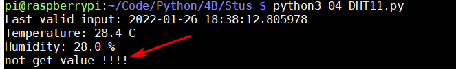
yellow.off()
print("not get value !!!!")
def fGetValue():
red.off()
yellow.off()
if __name__=='__main__':
try:
button.when_pressed = getValue
button.when_released = fGetValue
pause()
# while True:
# result = instance.read()
# if result.is_valid():
# print("Last valid input: " + str(datetime.datetime.now()))
#
# print("Temperature: %-3.1f C" % result.temperature)
# print("Humidity: %-3.1f %%" % result.humidity)
#
# time.sleep(6)
except KeyboardInterrupt:
print("Cleanup")
GPIO.cleanup()
Final effect:
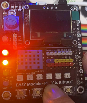
After pressing the key, the red light is on, and the value is obtained successfully (the yellow light is on):
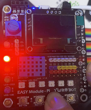
After pressing the key, the red light is on, the value acquisition fails, and the yellow light is not on:
Summary:
For DHT11, it is very important to obtain the clock information of the signal. If the clock cannot be obtained correctly, it is impossible to obtain the value or activate the sensor. python is not very good at this kind of code that needs us to control. It is better to use c or golang.