Research and implementation of temperature control automatic baking system
Research and implementation of tea automatic baking system. The basic principle and system block diagram of tea automatic baking system are studied. Through the temperature detection module, three different temperature data can be detected in real time, and the data can be transmitted to the computer through Bluetooth module. Using the temperature control circuit, PID algorithm and 51 single chip microcomputer for control and data processing, the temperature can be controlled accurately and in real time. The system is mainly composed of 51 single chip microcomputer minimum system, Bluetooth module, temperature sensing module, driving display circuit, output control circuit, power supply circuit, storage circuit, alarm circuit and key circuit output. The designed tea automatic baking system is used to collect the temperature of tea during baking. When the temperature is too high, it can automatically control to stop heating. The system has the advantages of easy control, reliable operation and high measurement accuracy. It can detect and control in real time.
Key words: temperature detection, temperature control, PID algorithm, data transmission
Research and implementation of automatic tea baking system
Automatic tea baking system research and implementation introduces the automatic tea baking system basic principle and system block diagram.The system can real-time monitoring three different temperature data and transmits the data to a computer thought by Bluetooth module.The system is use the temperature control circuit and PID algorithm and 51 single-chip microcomputer control and data processing to accurately control the temperature. The system is mainly composed of 51 single chip microcomputer system, Bluetooth module, temperature sensor module, driver display circuit, output control circuit, power circuit, storage circuit, alarm circuit and key circuit output. The tea automatic baking system is used to collect the temperature of the tea in the baking process. This system has the advantages of easy control, reliable operation, high measurement accuracy, real-time detection and control.
Key Words: Temperature measurement, temperature control, PID algorithm, data transmission
Code + paper download address Download address
catalogue
Chapter 1 Introduction 1
1.1 research background 1
1.2 research significance 1
1.3 research contents 2
Chapter 2 system hardware circuit design 3
2.1 overall circuit scheme 3
2.2 minimum system of single chip microcomputer 3
2.2.1 STC89C51 chip 3
2.2.2 reset circuit 3
2.2.3 crystal oscillator circuit 4
2.3 drive display circuit and alarm circuit 4
2.3.1 LCD display circuit 4
2.3.2 buzzer and LED indication 6
2.4 DS18B20 temperature sensor 7
2.5 AT24C01 memory chip 8
2.6 G5LA-14 relay 8
2.7 HC-05 Bluetooth module 9
Chapter 3 system programming 11
3.1 main program11
3.2 status display subroutine 13
3.3 temperature setting subroutine 14
3.4 temperature comparison subroutine 15
3.5 PID controller 16
3.6 serial port data transmission program 1
Chapter 4 system test 1
4.1 module test 1
4.2 system function 1
Conclusion 2
Reference 3
Acknowledgements 4
Appendix 1 part of key source code and explanation 5
Appendix 2 system schematic diagram 23
Appendix 3 English literature translation 28
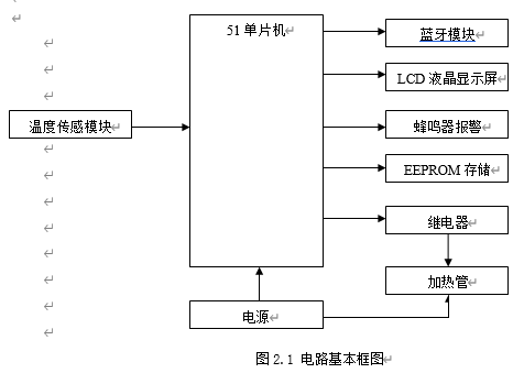
Overall circuit scheme
Overall circuit block diagram. In the design, I found that the Bluetooth module is suitable for transmitting small data. Compared with Wifi, using Bluetooth does not need to use the network, so I adopted the Bluetooth module design. The connection with computer and mobile phone is very convenient.
main program
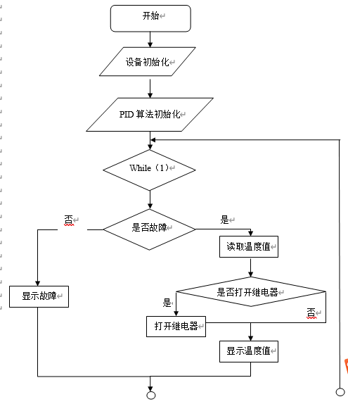
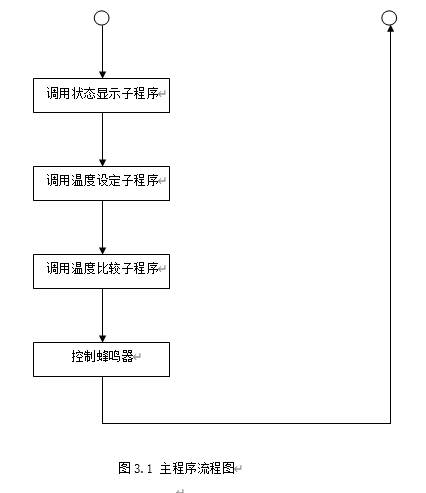
The main function of the main program is to read out the temperature value, process the temperature value, display the temperature value on the LCD screen and control the subroutine output. Press the key to set the temperature. When the temperature sensor fails, the buzzer will sound an alarm. If there is no fault, it will display normally and control the relay switch. As shown in Figure 3.1 main program flow chart.
Temperature setting subroutine
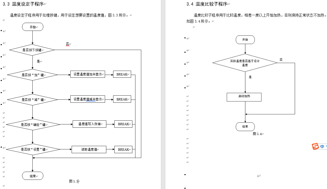
The temperature setting subroutine is used to process the keys and set the temperature value you want to set
System test
4.1 module test
Test of temperature acquisition module: when the actual temperature value changes, the LCD synchronously displays the actual temperature, and the acquisition module works normally.
LCD display test: first observe whether the LCD has external damage, and then power on. The LCD will display the temperature of temperature 1, temperature 2 and temperature 3. Press the key to observe whether the setting set1 displayed on the display changes set2 and set3. After testing, the LCD display can work normally.
Key test: when the key is long and on time, the data changes once, and when the key is short, the data changes according to the times of pressing the key. After detection, the key works normally.
Buzzer sounding test: Unplug the temperature sensing module to simulate the failure of the temperature sensor, the buzzer will sound an alarm, and the buzzer will work normally.
Test of temperature control module: set the set temperature. When the actual temperature of tea is lower than the set temperature, the relay opens to simulate the temperature of heating tea. When the actual temperature of tea is equal to or higher than the set temperature, the relay closes. The results show that the temperature control module works normally.
Bluetooth module test: data can be transmitted to computer and mobile phone through serial port, and Bluetooth module works normally.
4.2 system functions
After startup, the current status, including actual temperature and status, will be displayed on the LCD screen. Set the temperature value to be reached through independent keys. s3 is the plus key, s4 is the minus key, s5 is the OK key, s6 is the setting key. After pressing the OK key, when the actual temperature is less than the set temperature, the screen displays the heating and actual temperature, and turn on the heating tube control relay. When the actual temperature is higher than the set temperature, the constant temperature and actual temperature are displayed, and turn off the heating tube. When the temperature sensor fails, the abnormal liquid level will be displayed on the screen and the buzzer will give an alarm. You can set the temperature value at any time and update the status immediately after setting. The graduation project is a hardware, which includes the minimum system of single chip microcomputer, Bluetooth module, temperature sensing module, driving display circuit, output control circuit, power circuit, storage circuit, alarm circuit and key circuit output. Therefore, the system functions also include reset function, storage function, alarm function, display function and so on. The external relay is well controlled and connected with a heating tube, which is actually made by heating fast. The heating fast is cut into two parts, one with a plug and the other with a heating tube, which are separately installed into the output control circuit. The heating tube is controlled by the relay switch, and the plug is inserted into the 220V power supply to provide energy for the heating tube. For safety reasons, the heating function is not directly tested.
Partial code
#include "LCD1602.h"
#include "UART.H"
#include<intrins.h>
#include<math.h>
#include<string.h>
#include <stdio.h>

struct PID {
unsigned int SetPoint; // Set target Desired Value
unsigned int Proportion; // Proportional Const
unsigned int Integral; // Integral Const
unsigned int Derivative; // Differential const
unsigned int LastError; // Error[-1]
unsigned int PrevError; // Error[-2]
unsigned int SumError; // Sums of Errors
};

struct PID spid; // PID Control Structure
unsigned int rout; // PID Response (Output)
unsigned int rin; // PID Feedback (Input)

unsigned char high_time,low_time,count=0;//Duty cycle adjustment parameters
unsigned char high_time1,low_time1,count1=0;//Duty cycle adjustment parameters
unsigned char high_time2,low_time2,count2=0;//Duty cycle adjustment parameters

sbit bell=P3^6;		     //Buzzer
sbit temper_relay=P2^3;	 //Heating solenoid valve
sbit temper_relay1=P2^4; //Heating solenoid valve
sbit temper_relay2=P2^5; //Heating solenoid valve


uint real_temper=0;		 //Actual temperature value
uint real_temper1=0;     //Actual temperature value
uint real_temper2=0;	 //Actual temperature value
uchar eeprom_value=0,set_temper=0;//eeprom value and set temperature value
uchar eeprom_value1=0,set_temper1=0;//eeprom value and set temperature value
uchar eeprom_value2=0,set_temper2=0;//eeprom value and set temperature value

uchar Temper_Flag=0,keep_temp_flag=0; //Temperature detection and constant temperature mark
uchar Temper_Flag1=0,keep_temp_flag1=0; //Temperature detection and constant temperature mark
uchar Temper_Flag2=0,keep_temp_flag2=0; //Temperature detection and constant temperature mark

uchar select_set=0;
uchar set_flag=0;	//Set temperature flag
uchar bell_count;	//Number of buzzer alarms
uchar time_flag=0;

//Timer initialization 50ms
void Time_Init(void)
{
   TMOD=0X01;
   TH0=(65536-1000)/256;
   TL0=(65536-1000)/256;
   ET0=1;
   EA=1;
   TR0=1;
}

void PIDInit (struct PID *pp)
{
 memset ( pp,0,sizeof(struct PID));
}

//PID calculation part
unsigned int PIDCalc( struct PID *pp, unsigned int NextPoint )
{
unsigned int dError,Error;
Error = pp->SetPoint - NextPoint; // deviation
pp->SumError += Error; // integral
dError = pp->LastError - pp->PrevError; // Current differential
pp->PrevError = pp->LastError;
pp->LastError = Error;
return (pp->Proportion * Error // Scale item
+ pp->Integral*pp->SumError // Integral term
+ pp->Derivative*dError); // Differential term
}

//Temperature comparison processing subroutine
void compare_temper1(void)
{
  unsigned char i;
     if((set_temper)>(real_temper/10))
     {
      if((set_temper)-(real_temper/10)>1) //The difference of 1 degree is the beginning of PID regulation
         {
          high_time=100;  //Always turn on heating when the actual temperature is more than one degree lower than the set temperature
          low_time=0;
         }
      else
         {
           for(i=0;i<10;i++) //Calculate 10 times
             {
			    EA=0; //Turn off the interrupt to prevent affecting the reading of data
			    real_temper=DS18B20_Read_Tempereture(1);
				EA=1;
                rin = real_temper; // Read Input
                rout = PIDCalc ( &spid,rin ); // Perform PID Interation
             }
           if (high_time<=100)	 //Conversion adjustment value
             high_time=(unsigned char)(rout/800);
           else
             high_time=100;
           low_time= (100-high_time);
         }
     }
      else if((set_temper)<=(real_temper/10)) //Turn off heating when the actual temperature is higher than the set temperature
             {
               if((set_temper)-(real_temper/10)>0)//Adjust back and forth
                 {
                   high_time=0;
                   low_time=100;
                 }
               else
               {
                 for(i=0;i<10;i++)
                 {
				    EA=0;
				    real_temper=DS18B20_Read_Tempereture(1);
					EA=1;
                    rin = real_temper; // Read Input
                    rout = PIDCalc ( &spid,rin ); // Perform PID Interation
                 }
                 if (high_time<100)
                   high_time=(unsigned char)(rout/10000);
                 else
                   high_time=0;
                 low_time= (100-high_time);
               }
             }
 }

//Temperature comparison processing subroutine
//void compare_temper1(void)
//{
//  unsigned char i;
//     if((set_temper1)>(real_temper1/10))
//     {
//      If ((set_temper1) - (real_temper1 / 10) > 1) / / start PID adjustment when the difference is 1 degree
//         {
//          high_time1=100;  // Always turn on heating when the actual temperature is more than one degree lower than the set temperature
//          low_time1=0;
//         }
//      else
//         {
//           For (I = 0; I < 10; I + +) / / calculate 10 times
//             {
//			    EA=0; // Turn off the interrupt to prevent affecting the reading of data
//			    real_temper1=DS18B20_Read_Tempereture(2);
//				EA=1;
//                rin = real_temper1; // Read Input
//                rout = PIDCalc ( &spid,rin ); // Perform PID Interation
//             }
//           if (high_time1<=100) 	 // Conversion adjustment value
//             high_time1=(unsigned char)(rout/800);
//           else
//             high_time1=100;
//           low_time1= (100-high_time1);
//         }
//     }
//      Else if ((set_temper1) < = (real_temper1 / 10)) / / turn off heating when the actual temperature is higher than the set temperature
//             {
//               If ((set_temper1) - (real_temper1 / 10) > 0) / / adjust back and forth
//                 {
//                   high_time1=0;
//                   low_time1=100;
//                 }
//               else
//               {
//                 for(i=0;i<10;i++)
//                 {
//				    EA=0;
//				    real_temper1=DS18B20_Read_Tempereture(2);
//					EA=1;
//                    rin = real_temper1; // Read Input
//                    rout = PIDCalc ( &spid,rin ); // Perform PID Interation
//                 }
//                 if (high_time1<100)
//                   high_time1=(unsigned char)(rout/10000);
//                 else
//                   high_time1=0;
//                 low_time1= (100-high_time1);
//               }
//             }
// }
//
//Temperature comparison processing subroutine
//void compare_temper1(void)
//{
//  unsigned char i;
//     if((set_temper2)>(real_temper2/10))
//     {
//      If ((set_temper2) - (real_temper2 / 10) > 1) / / start PID adjustment when the difference is 1 degree
//         {
//          high_time2=100;  // Always turn on heating when the actual temperature is more than one degree lower than the set temperature
//          low_time2=0;
//         }
//      else
//         {
//           For (I = 0; I < 10; I + +) / / calculate 10 times
//             {
//			    EA=0; // Turn off the interrupt to prevent affecting the reading of data
//			    real_temper2=DS18B20_Read_Tempereture(3);
//				EA=1;
//                rin = real_temper2; // Read Input
//                rout = PIDCalc ( &spid,rin ); // Perform PID Interation
//             }
//           if (high_time2<=100) 	 // Conversion adjustment value
//             high_time2=(unsigned char)(rout/800);
//           else
//             high_time2=100;
//           low_time2= (100-high_time2);
//         }
//     }
//      Else if ((set_temper2) < = (real_temper2 / 10)) / / turn off heating when the actual temperature is higher than the set temperature
//             {
//               If ((set_temper2) - (real_temper2 / 10) > 0) / / adjust back and forth
//                 {
//                   high_time2=0;
//                   low_time2=100;
//                 }
//               else
//               {
//                 for(i=0;i<10;i++)
//                 {
//				    EA=0;
//				    real_temper2=DS18B20_Read_Tempereture(3);
//					EA=1;
//                    rin = real_temper2; // Read Input
//                    rout = PIDCalc ( &spid,rin ); // Perform PID Interation
//                 }
//                 if (high_time2<100)
//                   high_time2=(unsigned char)(rout/10000);
//                 else
//                   high_time2=0;
//                 low_time2= (100-high_time2);
//               }
//             }
// }
//

//Read the temperature setting from EEPROM
void Read_Set_EEPROM_Value(void)
{
   	set_temper=X24C02_Read(10);
	set_temper1=X24C02_Read(11);
	set_temper2=X24C02_Read(12);
}

//Key processing temperature value setting
void Set_Temper_Value(void)
{
    uchar value_temp;
	value_temp=P3&0x3C;	   //Obtain whether the key is pressed according to the key connection port
	if(value_temp!=0x3c)
	{
	   _delay_ms(5);	  //Debounce
	   if(value_temp!=0x3c)	 //Confirm again whether the key is pressed
	   {
		    switch(value_temp)
			{
			   case 0x38: //Add key
			        if(set_flag==1)	   //Valid only after the setting key is pressed
					{
					   if(select_set==1)
					   {
					      if(eeprom_value<99) //The upper limit of temperature value is 99 degrees
						  eeprom_value++;	  //Set temperature value plus
						  LCD_write_Num_1(13,1,eeprom_value,2); //Display set temperature value
					   }
					   else if(select_set==2)
					   {
					      if(eeprom_value1<99) //The upper limit of temperature value is 99 degrees
						  eeprom_value1++;	  //Set temperature value plus
						  LCD_write_Num_1(13,1,eeprom_value1,2); //Display set temperature value
					   }
					   else if(select_set==3)
					   {
					      if(eeprom_value2<99) //The upper limit of temperature value is 99 degrees
						  eeprom_value2++;	  //Set temperature value plus
						  LCD_write_Num_1(13,1,eeprom_value2,2); //Display set temperature value
					   }
					}
			   break;
			   case 0x34: //Key reduction
			        if(set_flag==1)	  //Valid only after the setting key is pressed
					{
					   if(select_set==1)
					   {
					      if(eeprom_value>0)//When less than the lower limit
						  eeprom_value--;	//Set temperature value minus
						  LCD_write_Num_1(13,1,eeprom_value,2); //Display set temperature value
					   }
					   else	 if(select_set==2)
					   {
					      if(eeprom_value1>0)//When less than the lower limit
						  eeprom_value1--;	//Set temperature value minus
						  LCD_write_Num_1(13,1,eeprom_value1,2); //Display set temperature value
					   }
					   else	 if(select_set==3)
					   {
					      if(eeprom_value2>0)//When less than the lower limit
						  eeprom_value2--;	//Set temperature value minus
						  LCD_write_Num_1(13,1,eeprom_value2,2); //Display set temperature value
					   }
					}
			   break;
			   case 0x2c: //determine
			        if(set_flag==1)	 //Valid only after the setting key is pressed
			        {
				        set_flag=0;	 //Exit setup
					    LCD_write_str(8,1,"S:        ");
						if(select_set==1)
					    {
							X24C02_Write(10,eeprom_value); //Write settings to EEPROM
							_delay_ms(5);	   //Delayed EEPROM cannot be read immediately after writing and needs to wait for a certain time
							Read_Set_EEPROM_Value(); //Read EEPROM reassign set comparison value
					    }
						else if(select_set==2)
					    {
							X24C02_Write(11,eeprom_value1); //Write settings to EEPROM
							_delay_ms(5);	   //Delayed EEPROM cannot be read immediately after writing and needs to wait for a certain time
							Read_Set_EEPROM_Value(); //Read EEPROM reassign set comparison value
					    }
						else if(select_set==3)
					    {
							X24C02_Write(12,eeprom_value2); //Write settings to EEPROM
							_delay_ms(5);	   //Delayed EEPROM cannot be read immediately after writing and needs to wait for a certain time
							Read_Set_EEPROM_Value(); //Read EEPROM reassign set comparison value
					    }
						select_set=0;
					}
			   break;
			   case 0x1c: //set up
			        select_set++;
					if(select_set==4)select_set=1;
					set_flag=1;	 //Schedule setting
					if(select_set==1)
					{
						LCD_write_str(8,1,"Set1:   ");
						eeprom_value=X24C02_Read(10);	//Read the value in EEPROM and set it
						LCD_write_Num_1(13,1,eeprom_value,2);  //Display setting initial value
					}
					else if(select_set==2)
					{
						LCD_write_str(8,1,"Set2:   ");
						eeprom_value1=X24C02_Read(11);	//Read the value in EEPROM and set it
						LCD_write_Num_1(13,1,eeprom_value1,2);  //Display setting initial value
					}
					else if(select_set==3)
					{
						LCD_write_str(8,1,"Set3:   ");
						eeprom_value2=X24C02_Read(12);	//Read the value in EEPROM and set it
						LCD_write_Num_1(13,1,eeprom_value2,2);  //Display setting initial value
					}

			   break;
			}
	   }
	   while(value_temp!=0x3c)value_temp=P3&0x3C; //Release detection
	}
}

//Fault detection
void InDetect(void)
{
   if(DS18B20_Init(1)!=0) //Temperature sensor failure
   {
	   Temper_Flag=1;	//Set flag
   }
   else
   {
       Temper_Flag=0;
   }
   if(DS18B20_Init(2)!=0) //Temperature sensor failure
   {
	   Temper_Flag1=1;	//Set flag
   }
   else
   {
       Temper_Flag1=0;
   }
   if(DS18B20_Init(3)!=0) //Temperature sensor failure
   {
	   Temper_Flag2=1;	//Set flag
   }
   else
   {
       Temper_Flag2=0;
   }

   if((real_temper/10)<set_temper) //Comparison between actual temperature and set temperature
   {
       keep_temp_flag=0;
   }
   else
   {
       keep_temp_flag=1;
   }
   if((real_temper1/10)<set_temper1) //Compare with actual temperature setting
   {
       keep_temp_flag1=0;
   }
   else
   {
       keep_temp_flag1=1;
   }
   if((real_temper2/10)<set_temper2) //Comparison between actual temperature and set temperature
   {
       keep_temp_flag2=0;
   }
   else
   {
       keep_temp_flag2=1;
   }
}

//Status display
void State_Display(void)
{
   InDetect(); //Fault detection
   if(set_flag==0)//Display when not set
   {
	   if((Temper_Flag==1)||(Temper_Flag1==1)||(Temper_Flag2==1))
	   {
	      LCD_write_str(10,1,"Error ");	 //Abnormal temperature
	   }
	   else
	   {
		 if((keep_temp_flag==0)||(keep_temp_flag1==0)||(keep_temp_flag2==0))
		 {
		   	LCD_write_str(10,1,"Hot   ");//heating
		 }
		 else
		 {
		    LCD_write_str(10,1,"Normal");	//normal
		 }
	   }
   }
}

//Output buzzer and relay control
void Output_Control(void)
{
   	if((Temper_Flag==1)||(Temper_Flag1==1)||(Temper_Flag2==1))//Alarm in case of temperature failure
	{
	   	bell_count=4;
	}
	else  bell_count=0;
}

//Device initialization function
void Device_Init(void)
{
    Time_Init();
	Init_uart();
  	LCD_init();
	DS18B20_Init(1);
	DS18B20_Init(2);
	DS18B20_Init(3);
    LCD_write_str(0,0,"T1:");
	LCD_write_str(9,0,"T2:");
	LCD_write_str(0,1,"T3:");
	LCD_write_str(8,1,"S:        ");
	Read_Set_EEPROM_Value();
}

//Main function
int main(void)
{
    Device_Init(); //Device initialization
	PIDInit ( &spid ); // Initialize PID
	spid.Proportion = 10; // Set PID Coefficients
	spid.Integral = 8;
	spid.Derivative =6;
	spid.SetPoint = 100; // Set PID Setpoint
    while(1)
    {
	   if(time_flag==1)
	   {
	       time_flag=0;
		   if((Temper_Flag==0))  //When the temperature sensor has no fault
		   {
		       EA=0;
			   real_temper=DS18B20_Read_Tempereture(1); //Read temperature value
			   EA=1;
		       LCD_write_Num(3,0,real_temper,4);  //Display temperature value
			   printf("Temper1_Value=%f\r\n",real_temper/10.0);
		   }
		   else
		   {
		     LCD_write_str(3,0,"Eor "); //When the temperature sensor is faulty
			 printf("Temper1_Value=Error!\r\n");
		   }

		   if((Temper_Flag1==0))  //When the temperature sensor has no fault
		   {
		       EA=0;
			   real_temper1=DS18B20_Read_Tempereture(2); //Read temperature value
			   EA=1;
		       LCD_write_Num(12,0,real_temper1,4);  //Display temperature value
			   printf("Temper2_Value=%f\r\n",real_temper1/10.0);
		   }
		   else
		   {
		       LCD_write_str(12,0,"Eor "); //When the temperature sensor is faulty
			   printf("Temper2_Value=Error!\r\n");
		   }

		   if((Temper_Flag2==0))  //When the temperature sensor has no fault
		   {
			   EA=0;
			   real_temper2=DS18B20_Read_Tempereture(3); //Read temperature value
			   EA=1;
		       LCD_write_Num(3,1,real_temper2,4);  //Display temperature value
			   printf("Temper3_Value=%f\r\n",real_temper2/10.0);
		   }
		   else
		   {
		       LCD_write_str(3,1,"Eor "); //When the temperature sensor is faulty
			   printf("Temper3_Value=Error!\r\n");
		   }
		   printf("==================================\r\n");
	   }
	   State_Display();
	   Set_Temper_Value();
	   compare_temper1();
	   //compare_temper2();
	   //compare_temper3();
	   Output_Control();
    }
}

//timer interrupt
void Time0(void) interrupt 1
{
   static uchar count=0;
   static uint m=0;
   TH0=(65536-1000)/256;
   TL0=(65536-1000)/256;

   m++;
   count++;
   //count1++;
   //count2++;
   if(m==1000) //1S timing
   {
     m=0;
	 time_flag=1;
	 if(bell_count>0)
    {
       bell=~bell;//The buzzer sign is reversed
       bell_count--;//Decrease in frequency
    }
    else bell=1;//Turn off the buzzer when the number of times reaches
   }
   if(count<=(high_time))
     temper_relay=0;
   else if(count<=100)
     {
      temper_relay=1;
      }
   else
      count=0;

//   if(count1<=(high_time1))
//     temper_relay1=0;
//   else if(count<=100)
//     {
//      temper_relay1=1;
//      }
//   else
//      count1=0;
//
//   if(count2<=(high_time2))
//     temper_relay2=0;
//   else if(count2<=100)
//     {
//      temper_relay2=1;
//      }
//   else
//      count2=0;
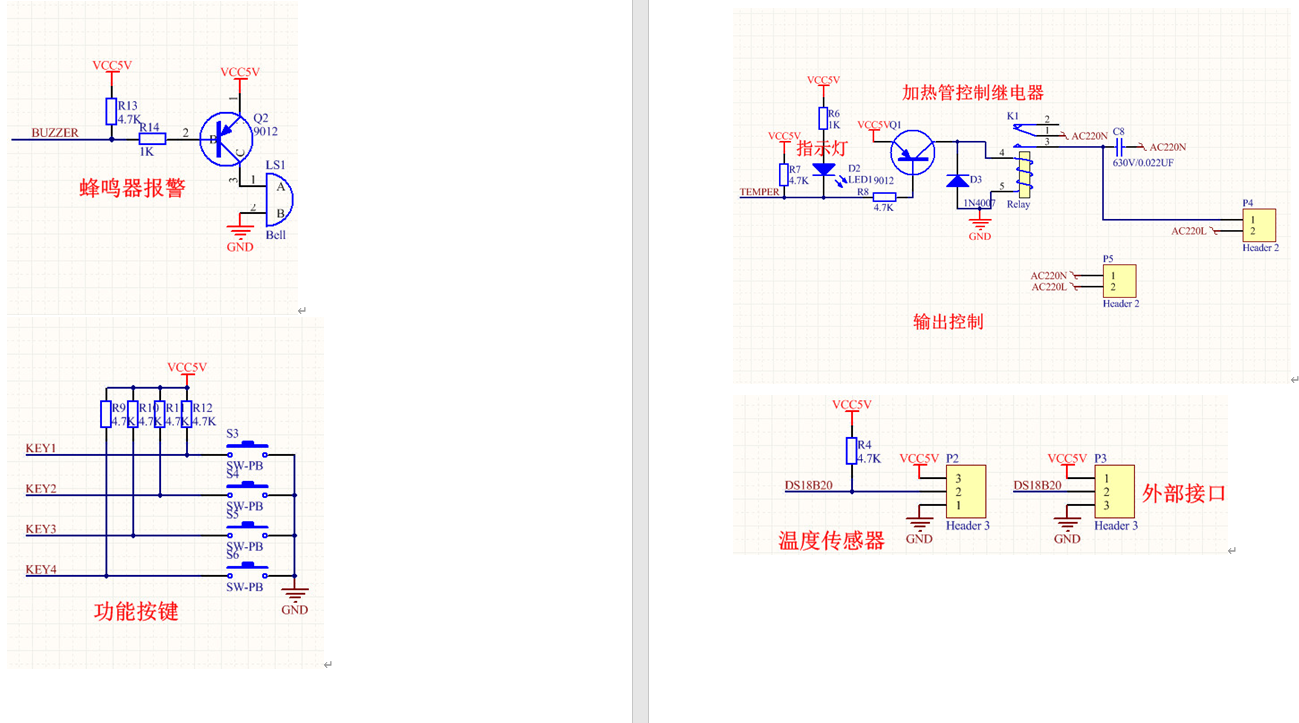
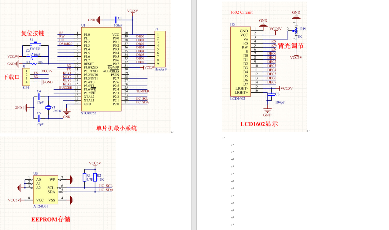
Circuit diagram
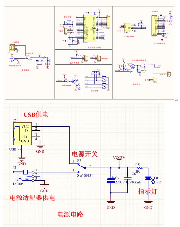
System design drawing and power module:
Temperature control module
