Experimental topology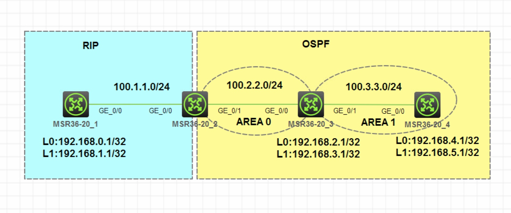
Note: unless otherwise specified, R1 or SW1 in the description corresponds to the device with the number at the end of the device name in the topology, and R2 or SW2 corresponds to the device with the number at the end of the device name in the topology
Equipment, and so on; In addition, in the same network segment, the host bit of the IP address is its device number. For example, if the g0/0 interface of R3 is 192.168 1.0/24
Network segment, its IP address is 192.168 1.3/24, and so on
Experimental requirements
- Configure the IP address as shown in the figure. Use the loopback port on R1, R3 and R4 to simulate the service network segment
- R1 and R2 run RIPv2, R2, R3 and R4 run OSPF, and their protocols are interconnected internally
- Two way routing is configured between RIP and OSPF. Except for the service network segment on R4, the routes of other service network segments are introduced into the other party's protocol
- Using route filtering, R4 cannot learn the service network segment route of R1. It is required to use prefix list for matching. RIP protocol messages cannot appear in OSPF area
Experimental solution
- Configure IP address omitted
- Configuring RIP and OSPF is omitted
- Two way routing is configured between RIP and OSPF. Except for the service network segment on R4, the routes of other service network segments are introduced into the other party's protocol
Analysis: according to the requirements, it is known that all RIP routes need to be introduced to OSPF on R2, and 192.168 of OSPF 2.1/32 and
192.168. The route of 3.1/32 network segment is introduced into RIP, 192.168 4.1/32 and 192.168 The routes of 5.1/32 network segments should be filtered when they are introduced. Therefore, when RIP is introduced into OSPF, there is no need to configure any routing strategy, but when RIP is introduced into OSPF
When, you need to use the routing policy to match only the service network segments on R3. According to the matching process of the routing policy, you only need to configure one node to grab R3
Business network segment on; There is no need to configure any Apply clause because it does not involve modifying routing properties
Step 1: create ACL on R2 to match the service network segment route on R3, and filter out other network segment routes
[R2]acl basic 2000
/**		The allowable source is 192.168 2.0-192.168. 3.0, because it is a 23 bit mask 		**/
[R2-acl-ipv4-basic-2000]rule permit source 192.168.2.0 0.0.1.255
ACL (access control list). By using ACL, you can specify IP address and subnet range to match the destination network segment address or next hop address of routing information.
Step 2: create a routing policy on R2 and associate ACL S
[R2]route-policy o2r permit node 10
[R2-route-policy-o2r-10]if-match ip address acl 2000
Step 3: introduce OSPF routing in RIP, call routing policy, and only introduce service network segments on R2
[R2-rip-1]import-route ospf route-policy o2r
Step 4: introduce RIP routing in OSPF
[R2-ospf-1]import-route rip
Effect test: check the routing table on R1 and find that only the service network segment routing of R3 has been learned. Check the routing table on R3 and learn the service network segment routing on R1
[R1]display ip routing-table

Destinations : 17       Routes : 17

Destination/Mask   Proto   Pre Cost        NextHop         Interface
0.0.0.0/32         Direct  0   0           127.0.0.1       InLoop0
100.1.1.0/24       Direct  0   0           100.1.1.1       GE0/0
100.1.1.0/32       Direct  0   0           100.1.1.1       GE0/0
100.1.1.1/32       Direct  0   0           127.0.0.1       InLoop0
100.1.1.255/32     Direct  0   0           100.1.1.1       GE0/0
100.2.2.0/24       RIP     100 1           100.1.1.2       GE0/0
127.0.0.0/8        Direct  0   0           127.0.0.1       InLoop0
127.0.0.0/32       Direct  0   0           127.0.0.1       InLoop0
127.0.0.1/32       Direct  0   0           127.0.0.1       InLoop0
127.255.255.255/32 Direct  0   0           127.0.0.1       InLoop0
192.168.0.1/32     Direct  0   0           127.0.0.1       InLoop0
192.168.1.1/32     Direct  0   0           127.0.0.1       InLoop0
192.168.2.1/32     RIP     100 1           100.1.1.2       GE0/0
192.168.3.1/32     RIP     100 1           100.1.1.2       GE0/0
224.0.0.0/4        Direct  0   0           0.0.0.0         NULL0
224.0.0.0/24       Direct  0   0           0.0.0.0         NULL0
255.255.255.255/32 Direct  0   0           127.0.0.1       InLoop0
[R3]display ip routing-table

Destinations : 22       Routes : 22

Destination/Mask   Proto   Pre Cost        NextHop         Interface
......
192.168.0.1/32     O_ASE2  150 1           100.2.2.2       GE0/0
192.168.1.1/32     O_ASE2  150 1           100.2.2.2       GE0/0
......
Using route filtering, R4 cannot learn the service network segment route of R1. It is required to use prefix list for matching
Analysis: by default, R1's service network segment route will be introduced by R2, and then enter OSPF with Type-5 LSA. It will be transmitted to all OSPF areas. R4 is required not to learn R1's service network segment route, so it is necessary to filter the route on R4. Because R1's service network segment route is transmitted in the form of Type-5LSA, Therefore, the method of filtering Type-3 LSA cannot be used. Only the calculated routing results can be filtered
It is required to use prefix list for route matching. After aggregation, the service network segment of R1 belongs to 192.168 0.0/23 network segment. However, due to the loopback simulation, the subnet mask of the route is 32 bits. Therefore, the mask range needs to be configured as less-eq32 and the action is reject. In addition, a rule needs to be configured to allow all
Step 1: create prefix list on R4 and reject 192.168 0.0/23 address range, and the mask range is less EQ 32, and all other routes are allowed
/*	Reject 192.168 0.0-0.1. For accurate matching, filter out network segments greater than 23 and less than or equal to 32 subnet mask	*/
[R4]ip prefix-list guolv index 10 deny 192.168.0.0 23 less-equal 32
[R4]ip prefix-list guolv index 20 permit 0.0.0.0 0 less-equal 32
Step 2: enter the OSPF view on R4, configure routing filtering, and call the prefix list created in the previous step
[R4-ospf-1]filter-policy prefix-list guolv import
Effect test: check the routing table on R4 and find that the service network segment routing of R1 cannot be learned
[R4]display ip routing-table

Destinations : 17       Routes : 17

Destination/Mask   Proto   Pre Cost        NextHop         Interface
0.0.0.0/32         Direct  0   0           127.0.0.1       InLoop0
100.2.2.0/24       O_INTER 10  2           100.3.3.3       GE0/0
100.3.3.0/24       Direct  0   0           100.3.3.4       GE0/0
100.3.3.0/32       Direct  0   0           100.3.3.4       GE0/0
100.3.3.4/32       Direct  0   0           127.0.0.1       InLoop0
100.3.3.255/32     Direct  0   0           100.3.3.4       GE0/0
127.0.0.0/8        Direct  0   0           127.0.0.1       InLoop0
127.0.0.0/32       Direct  0   0           127.0.0.1       InLoop0
127.0.0.1/32       Direct  0   0           127.0.0.1       InLoop0
127.255.255.255/32 Direct  0   0           127.0.0.1       InLoop0
192.168.2.1/32     O_INTER 10  1           100.3.3.3       GE0/0
192.168.3.1/32     O_INTER 10  1           100.3.3.3       GE0/0
192.168.4.1/32     Direct  0   0           127.0.0.1       InLoop0
192.168.5.1/32     Direct  0   0           127.0.0.1       InLoop0
224.0.0.0/4        Direct  0   0           0.0.0.0         NULL0
224.0.0.0/24       Direct  0   0           0.0.0.0         NULL0
255.255.255.255/32 Direct  0   0           127.0.0.1       InLoop0
RIP protocol message cannot appear in OSPF area
Analysis: since R2 needs to run rip through g0/0 port and R1, it is necessary to announce the network segment of g0/0 port in rip, but Rip can only announce the main network, and g0/1 port and g0/0 port connecting OSPF area belong to the same main network, so g0/1 Port will be forced to announce into rip, resulting in RIP sending protocol messages to OSPF area
Here, you need to configure the interface connecting the OSPF area as a silent interface in the RIP protocol of R2
Step 1: in the RIP of R2, configure the g0/1 Port as a silent interface
[R2-rip-1]silent-interface g0/1