Catalogue of series articles
RT thread (1) add external memory to memory management
RT thread (2) RTT SPI device driving process | LWIP + ENC28J60
catalogue
0.3 RTT startup and underlying driver initialization process
1.1 configure ENC28J60 interface
1.2 RTT equipment initialization
1.3 supplement HAL_SPI_MspInit
0 overview
In the previous article, I adapted the external SRAM of STM32 and loaded it into memory management. At present, the board suitable for RTT is used for remote control of industrial Internet of things, so there is an Ethernet port on the board. We need to open the lwip package of RTT.
Since this article contains some RTT source code analysis, if you only want to follow the steps, please view it in the following order
1.1 configure ENC28J60 interface
1.3 supplement HAL_SPI_MspInit
2 LWIP configuration
0.0 references
RT thread Development Guide
Enabling and debugging lwIP+ENC28J60 in RT thread studio environment
0.1 hardware resources
MCU: STM32F103ZET6
External RAM: XM8A51216
Ethernet interface chip: ENC28J60 (10Mbps)
0.2 software resources
Development environment: RT thread studio
RT-Thread: 4.0.3
lwip: 2.0.3
0.3 RTT startup and underlying driver initialization process
In the previous article, because RTT does not have FSMC type devices, we did not involve the RTT driver framework. Here we add the RTT startup process.
The entrance of RTT is called rtthread_ in [rt-thread to src] components.c. startup();:
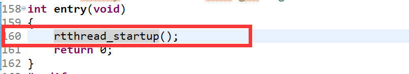
Go to define rtthread_ The location of startup () is also in this file, as follows:
int rtthread_startup(void)
{
rt_hw_interrupt_disable();
/* board level initialization
* NOTE: please initialize heap inside board initialization.
*/
rt_hw_board_init();
/* show RT-Thread version */
rt_show_version();
/* timer system initialization */
rt_system_timer_init();
/* scheduler system initialization */
rt_system_scheduler_init();
#ifdef RT_USING_SIGNALS
/* signal system initialization */
rt_system_signal_init();
#endif
/* create init_thread */
rt_application_init();
/* timer thread initialization */
rt_system_timer_thread_init();
/* idle thread initialization */
rt_thread_idle_init();
#ifdef RT_USING_SMP
rt_hw_spin_lock(&_cpus_lock);
#endif /*RT_USING_SMP*/
/* start scheduler */
rt_system_scheduler_start();
/* never reach here */
return 0;
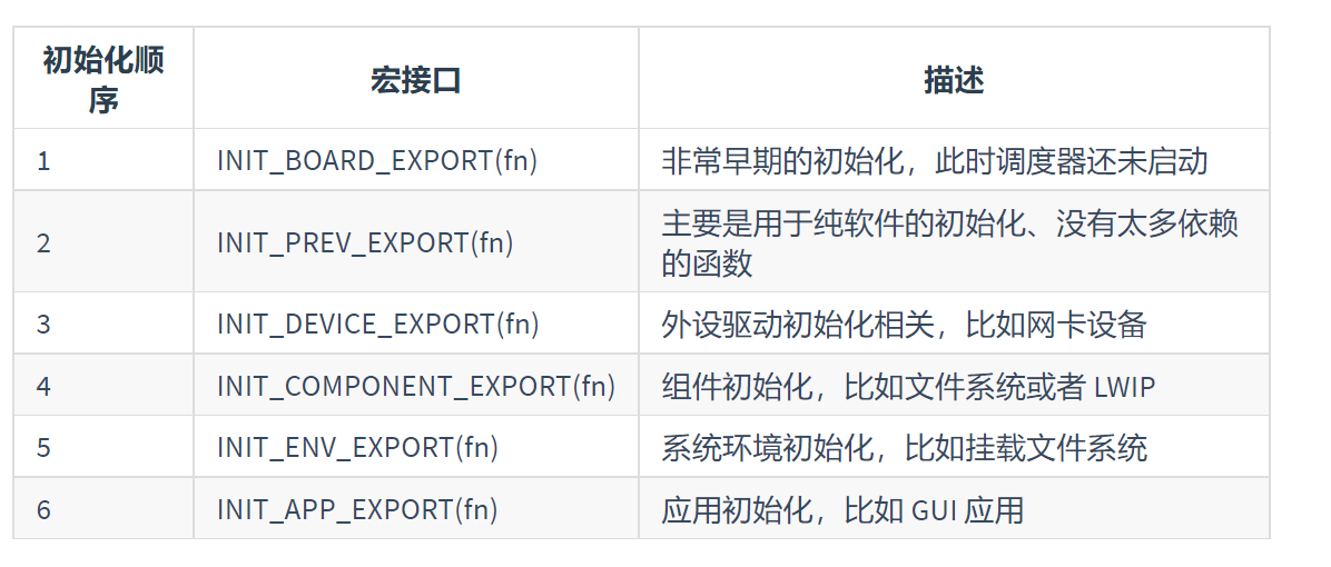
}RTT initializes all levels in turn. Refer to RTT manual for initialization sequence:
Let's go to RT_ hw_ board_ Definition of init(). This function is in [driver → board.c]. As follows:
RT_WEAK void rt_hw_board_init()
{
extern void hw_board_init(char *clock_src, int32_t clock_src_freq, int32_t clock_target_freq);
/* Heap initialization */
#if defined(RT_USING_HEAP)
rt_system_heap_init((void *) HEAP_BEGIN, (void *) HEAP_END);
#endif
hw_board_init(BSP_CLOCK_SOURCE, BSP_CLOCK_SOURCE_FREQ_MHZ, BSP_CLOCK_SYSTEM_FREQ_MHZ);
/* Set the shell console output device */
#if defined(RT_USING_DEVICE) && defined(RT_USING_CONSOLE)
rt_console_set_device(RT_CONSOLE_DEVICE_NAME);
#endif
/* Board underlying hardware initialization */
#ifdef RT_USING_COMPONENTS_INIT
rt_components_board_init();
#endif
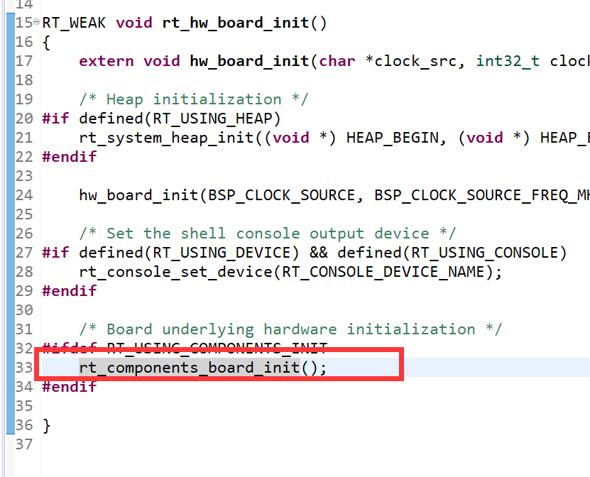
}There is the memory heap initialization we talked about last time, hw_board_init(...) is the initialization of board level hardware. Let's go to the definition of the function. In [driver → drv_common.c], as follows:
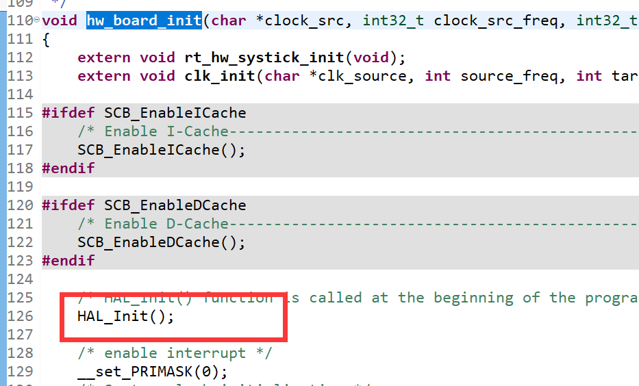
It finally involves the initialization of HAL library. Let's continue to HAL_ Definition of init(). This definition is in [project \ libraries\STM32F1xx_HAL_Driver\Src\stm32f1xx_hal.c].
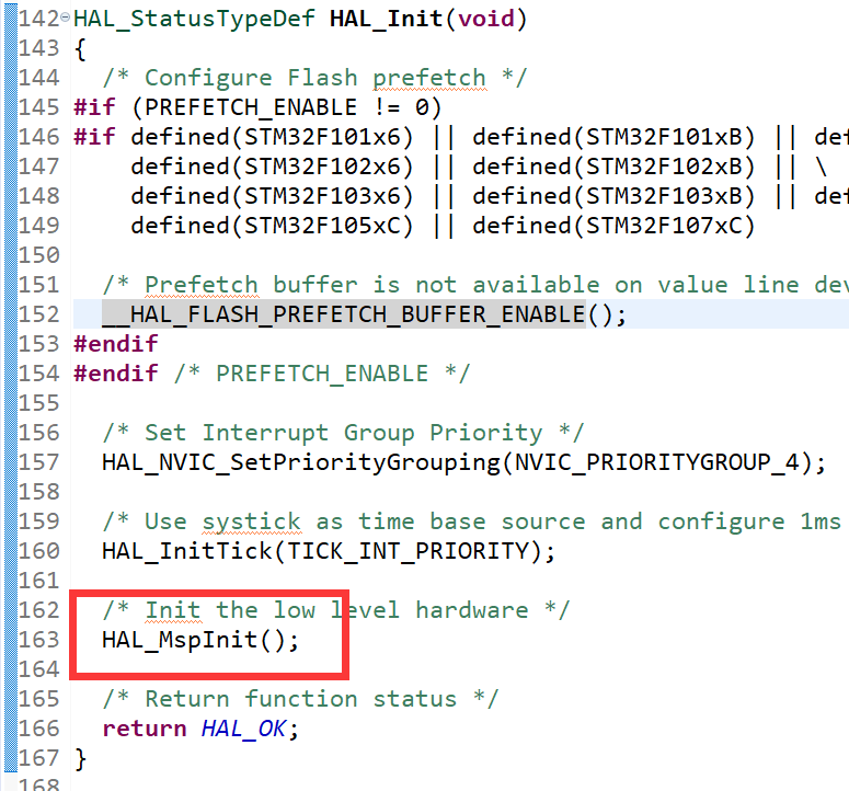
We can see in HAL_Init() initializes the system clock and interrupt, and Hal is called on line 163_ MspInit(). Continue to Hal_ Definition of mspinit(). There is a definition under the same file. However, the definition is of a break type, that is, if there is a hal of a non break type defined elsewhere_ Mspinit() does that. Then Hal in this file_ Mspinit () is meaningless. Let's search it in the project. It is found that there are no other definitions in the project, so when does RTT initialize the relevant hardware?
In fact, we only need to open [project \ driver\drv_spi.c] to find rt_hw_spi_init(...), and through INIT_BOARD_EXPORT(rt_hw_spi_init) enables it to run automatically after board level initialization. That is, RT in [project \ drvier\board.c]_ hw_ board_ RT of init() call_ components_ board_ Init().
1 driver writing
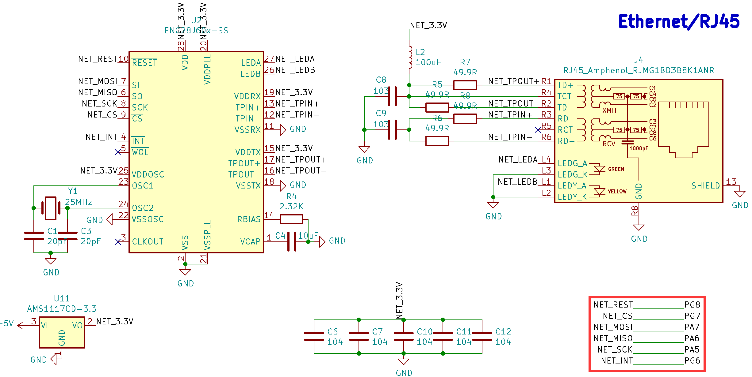
As shown in the figure below, it is the circuit diagram of ENC28J60 and the interface with STM32.
1.1 configure ENC28J60 interface
SPI interface is adopted between ENC28J60 and STM32. Here, we do not directly use the SPI driver of STM32 to connect to the interface of ENC28J60, but use the interface driver of RTT.
① Open the RT thread settings for the project.
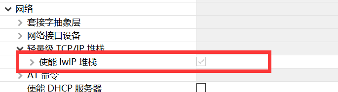
② Enable SPI bus and enable ENC28J60 SPI Ethernet interface of RTT
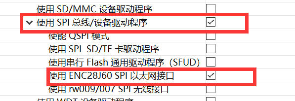
After we enable the interface of ENC28J60, the lwip protocol stack of RTT is automatically enabled. This is because the ENC28J60 interface relies on the lwip protocol stack.
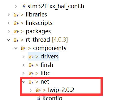
After saving the configuration, you can see the relevant files of lwip-2.0.2 in the directory of RT thread → components → net of the project.
Let's ignore the part of lwip and first solve the driving problem of ENC28J60.
③ Enable SPI1 in board.h
ENC28J60 is attached to SPI1 interface on my board, so we first open board.h. Search #define BSP_USING_SPI1 and uncomment. When this comment is cancelled, the SPI1 driver of RTT is enabled.
④ In stm32f1xx_ hal_ Cancel #define Hal in conf.h_ SPI_ MODULE_ Enabled comments
This is the HAL library with SPI enabled.
⑤ Create a new DRV in the [driver] directory_ ENC28J60. C file
In this file, we need to call the SPI device driver of RTT to mount ENC28J60.
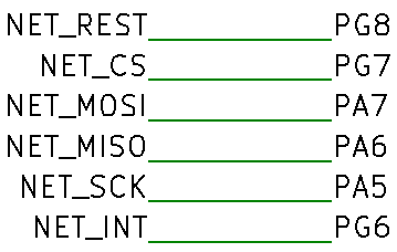
As shown in the figure below, ENC28J60 has 6 I/O ports, and the REST reset pin can be ignored because the ENC28J60 driver of RTT uses soft reset.
And then on DRV_ Add the following procedure to ENC28J60. C:
#include
#include
#include

#define ENC28J60_ Int 102 / / Pg6 ENC28J60 interrupt
static int rt_hw_enc28j60_init(void)
{
        rt_hw_spi_device_attach("spi1", "enc28", GPIOG, GPIO_PIN_7);//PG7 ENC28J60 film selection CS
        enc28j60_attach("enc28");
        rt_pin_mode(ENC28J60_INT, PIN_MODE_INPUT_PULLUP);
        rt_pin_attach_irq(ENC28J60_INT, PIN_IRQ_MODE_FALLING, (void(*)(void*))enc28j60_isr, RT_NULL);
        rt_pin_irq_enable(ENC28J60_INT, PIN_IRQ_ENABLE);
        return 0;
}
INIT_COMPONENT_EXPORT(rt_hw_enc28j60_init);
First, we use rt_hw_spi_device_attach("spi1", "spi10", GPIOC, GPIO_PIN_4) configure the enc28 device on the SPI1 bus to use PG7 as the chip selection pin CS.
Then use enc28j60_attach("enc28") mounts enc28j60. This function is provided by [project \ RT thread \ components \ drivers \ SPI \ enc28j60. C]. It will not be expanded temporarily.
Then set the interrupt pin of enc28j60. Here, define #define enc28j60 through the macro_ Int 102 definition. 102 is the number of PG6 pin in RTT, which can be found in [item \ drvier\drv_gpio.c].
By rt_pin_mode(ENC28J60_INT, PIN_MODE_INPUT_PULLUP) sets pin 102 as the pull-up input.
By RT_ pin_ attach_ IRQ (enc28j60_int, pin_irq_mode_failing, (void() (void)) enc28j60_isr, rt_null) set pin 102 as the falling edge trigger mode, and set the interrupt service function as ENC28J60_ isr.
Finally, through rt_pin_irq_enable(ENC28J60_INT, PIN_IRQ_ENABLE) enables the external interrupt.
Via INIT_COMPONENT_EXPORT(rt_hw_enc28j60_init) is imported to the component level for automatic initialization.
1.2 RTT equipment initialization
After searching in section 0.3, we know that RTT automatically runs spi initialization program during board level initialization. Next, we need to know what RTT initializes and whether there is anything we need to add.
We go to [project \ driver\drv_spi.c], where we can find rt_hw_spi_init(...), which reads as follows:
int rt_hw_spi_init(void)
{
    stm32_get_dma_info();
    return rt_hw_spi_bus_init();
}
INIT_BOARD_EXPORT(rt_hw_spi_init);
You can see that the first one is configured with SPIDMA, and the second one is the initial SPI bus. Let's go to rt_hw_spi_bus_init(). The whole function is relatively long, and only a part is put here. As follows:
static int rt_hw_spi_bus_init(void)
{
rt_err_t result;
for (int i = 0; i < sizeof(spi_config) / sizeof(spi_config[0]); i++)
{
spi_bus_obj[i].config = &spi_config[i];
spi_bus_obj[i].spi_bus.parent.user_data = &spi_config[i];
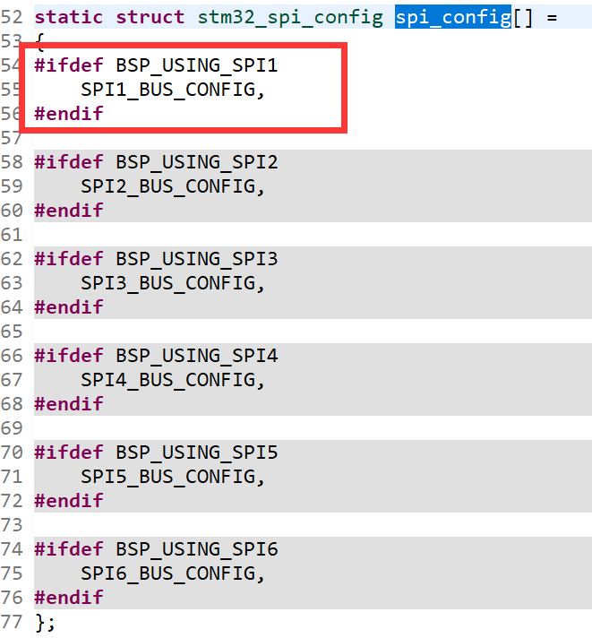
spi_bus_obj[i].handle.Instance = spi_config[i].Instance;It is obvious that this is an ergodic structure, SPI_ Our SPI bus list is saved in the config [] array. Also defined in the same file. You can see that we only enable SPI1 in board.h. so there is only SPI1 in the list
In RT_ hw_ spi_ bus_ At the end of init (), rt_ was called. spi_ bus_ Register (...) and passed in a structure stm_spi_ops. The structure is as follows:
static const struct rt_spi_ops stm_spi_ops =
{
    .configure = spi_configure,
    .xfer = spixfer,
};
We don't care how the kernel calls the structure, but we know SPI_ The configure function was passed. Let's take a look at SPI_ The contents of configure.
static rt_err_t spi_configure(struct rt_spi_device *device,
                              struct rt_spi_configuration *configuration)
{
    RT_ASSERT(device != RT_NULL);
    RT_ASSERT(configuration != RT_NULL);

    struct stm32_spi *spi_drv =  rt_container_of(device->bus, struct stm32_spi, spi_bus);
    spi_drv->cfg = configuration;

    return stm32_spi_init(spi_drv, configuration);
}
As you can see, STM32 is called inside_ spi_ init,stm32_ spi_ HAL_ is invoked in init. SPI_ Init(spi_handle).
HAL_SPI_Init is defined in stm32f1xx_ hal_ In SPI. C, the IO port of SPI is not initialized, but Hal is called_ SPI_ Mspinit, but HAL_SPI_MspInit is a__ The break function has nothing in it.
This means that the port of SPI1 is not initialized by RTT, which needs to be supplemented!!!!
1.3 supplement HAL_SPI_MspInit
We open board.c and add the following contents:
void HAL_SPI_MspInit(SPI_HandleTypeDef* hspi)
{
  GPIO_InitTypeDef GPIO_InitStruct = {0};
  if(hspi->Instance==SPI1)
  {
    /* Peripheral clock enable */
    __HAL_RCC_SPI1_CLK_ENABLE();

    __HAL_RCC_GPIOA_CLK_ENABLE();
    /**SPI1 GPIO to configure
    PA5     ------> SPI1_SCK
    PA6     ------> SPI1_MISO
    PA7     ------> SPI1_MOSI
    */
    GPIO_InitStruct.Pin = GPIO_PIN_5|GPIO_PIN_7;
    GPIO_InitStruct.Mode = GPIO_MODE_AF_PP;
    GPIO_InitStruct.Speed = GPIO_SPEED_FREQ_HIGH;
    HAL_GPIO_Init(GPIOA, &GPIO_InitStruct);

    GPIO_InitStruct.Pin = GPIO_PIN_6;
    GPIO_InitStruct.Mode = GPIO_MODE_INPUT;
    GPIO_InitStruct.Pull = GPIO_NOPULL;
    HAL_GPIO_Init(GPIOA, &GPIO_InitStruct);
  }
}
Here, we only supplemented SPI1. If other SPI interfaces are needed in the future, we will continue to supplement them.
2 LWIP configuration
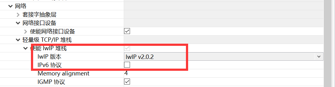
lwip version we choose 2.0.2 to achieve good compatibility.
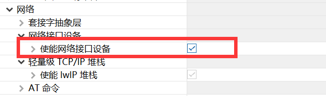
① Firstly, we use ENC28J60 as the network interface device, so we need to open [network] [network interface device] and [enable network interface device] in RTT configuration.
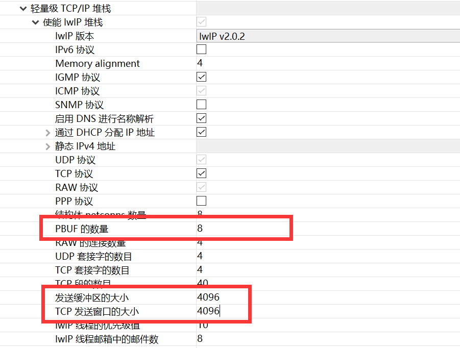
② Modify memory usage related parameters
Number of pbufs
The system defaults to 16 and modifies it to 8. A PBUF occupies 1576 bytes and is statically allocated. The more pbufs, the faster the receiving speed, but also the more memory consumption.
Size of TCP sending window and sending buffer
These two items are dynamically allocated, which can reduce the memory occupation by half after modification.
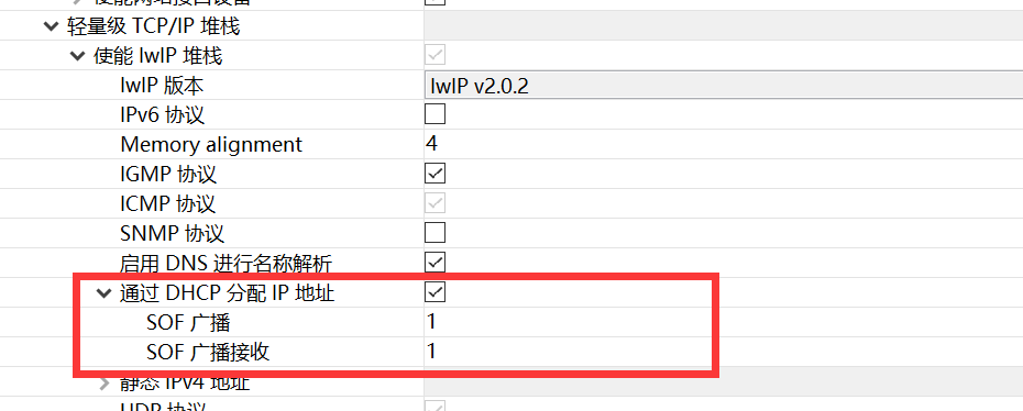
③ Enable DCHP to obtain IP address automatically
Get IP automatically
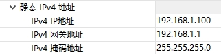
Static IP
④ Enable ping function

3 Summary
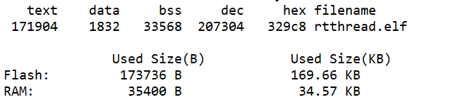
Compile the project after completion. The size of the project after compilation is:
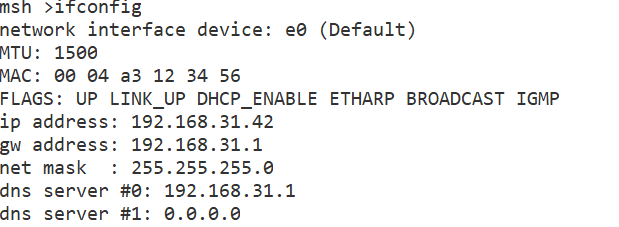
I use DHCP to automatically obtain the IP address, and then interrupt and enter the ifconfig command to view the network status. As shown in the figure below, I can see that the IP address has been obtained automatically.
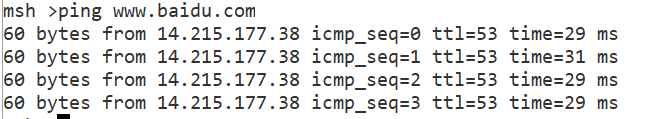
Use the ping command to ping www.baidu.com to test the network connection. The results are as follows: