The development environment of this article is based on keil5,rt-thread-4.0.3,env,STM32CubeMX, etc. the hardware is Delphi lenimo m3s development board. Please build and install the development environment by yourself. The content is simple and rough. Don't care too much. It mainly realizes the function.
This article does not talk about theoretical knowledge. For rttheard PWM device drive related knowledge, please go to the official website https://www.rt-thread.org/document/site/#/rt-thread-version/rt-thread-standard/programming-manual/device/pwm/pwm
This article also does not talk about rtthread transplantation and env environment construction. To understand the relevant knowledge, please go to the official website https://www.rt-thread.org/document/site/#/development-tools/env/env
STM32F103ZET6 is used as the main control chip in Delphi lenimo m3s development board. There are two red user function led lights, as shown in the figure below:
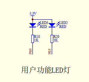
In this paper, led3 # is selected as the controlled led lamp. It can be seen from the figure that to control the brightness of led3 is to control the low-level duration of PB5 pin. The longer the duration, the brighter, and the shorter, the darker.
By querying the relevant manuals of STM32F103ZET6, we can see that PB5 corresponds to TIM3_CH2 channel, so we want to configure the PWM function of this pin. The method is as follows:
1. Configure relevant functions through env, enter the project directory, rt-thread-4.0.3\bsp\stm32\stm32f103-dofly-M3S, right click the mouse, and the following screen pops up
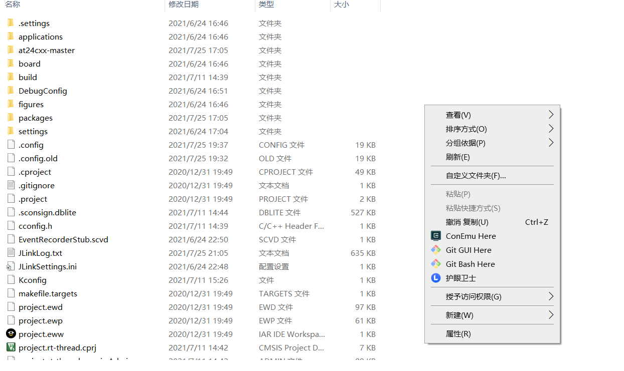
Select ConEmu Here and the following screen will pop up
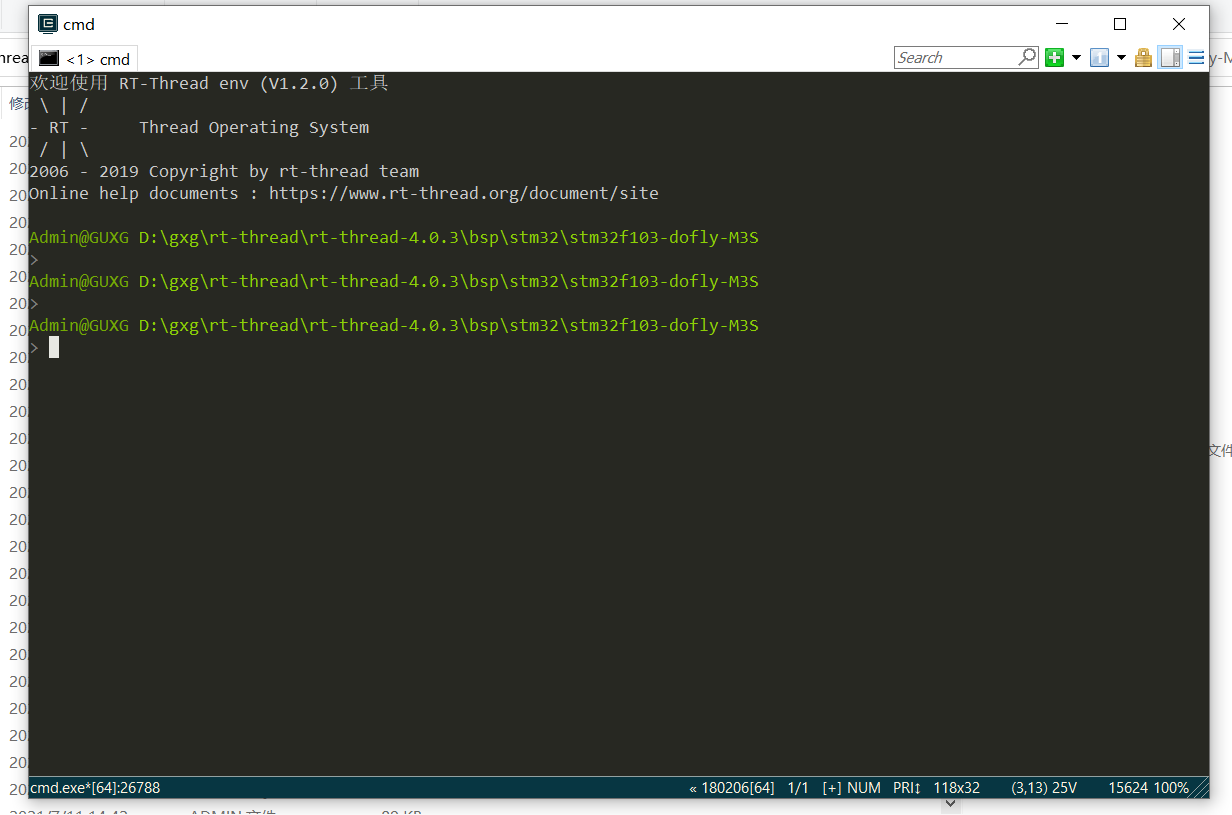
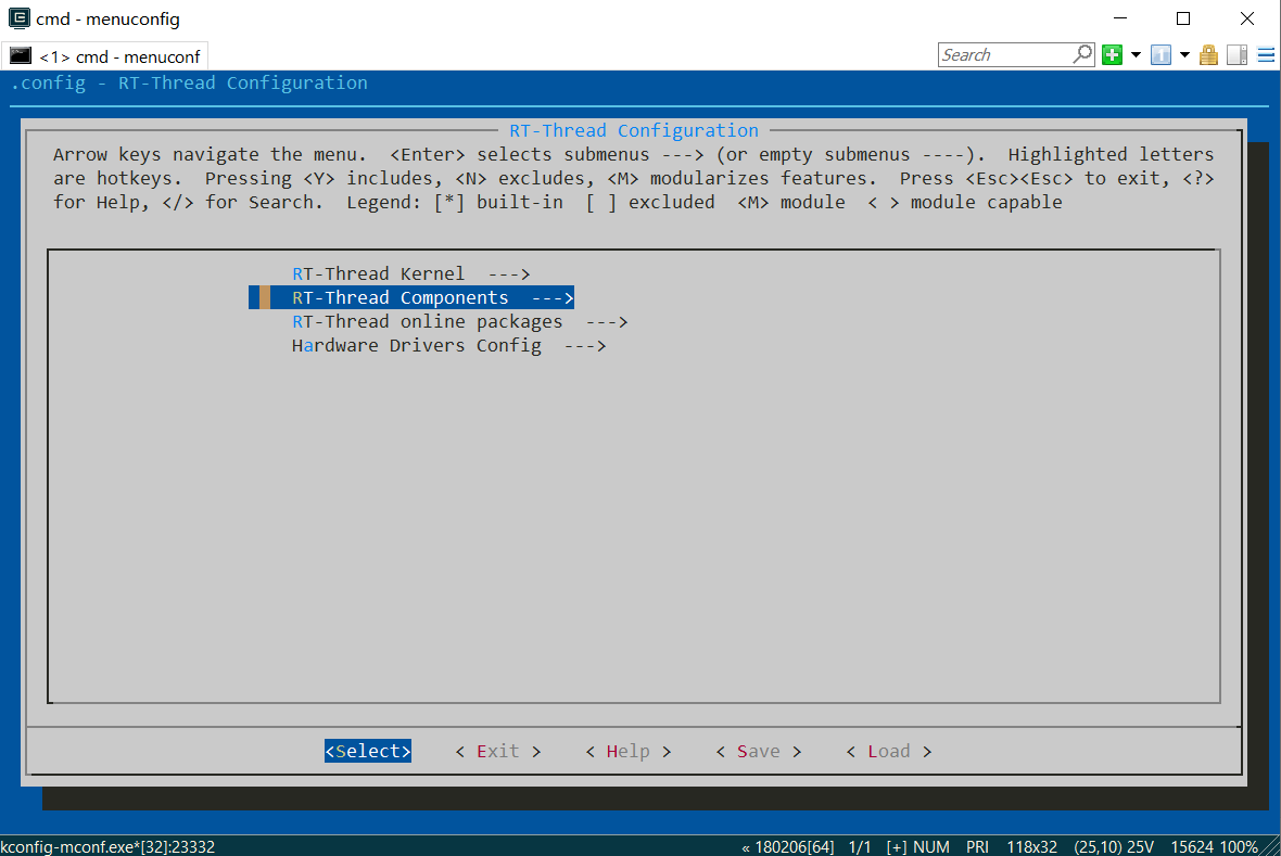
Enter menuconfig and press enter to open the configuration screen, as follows:
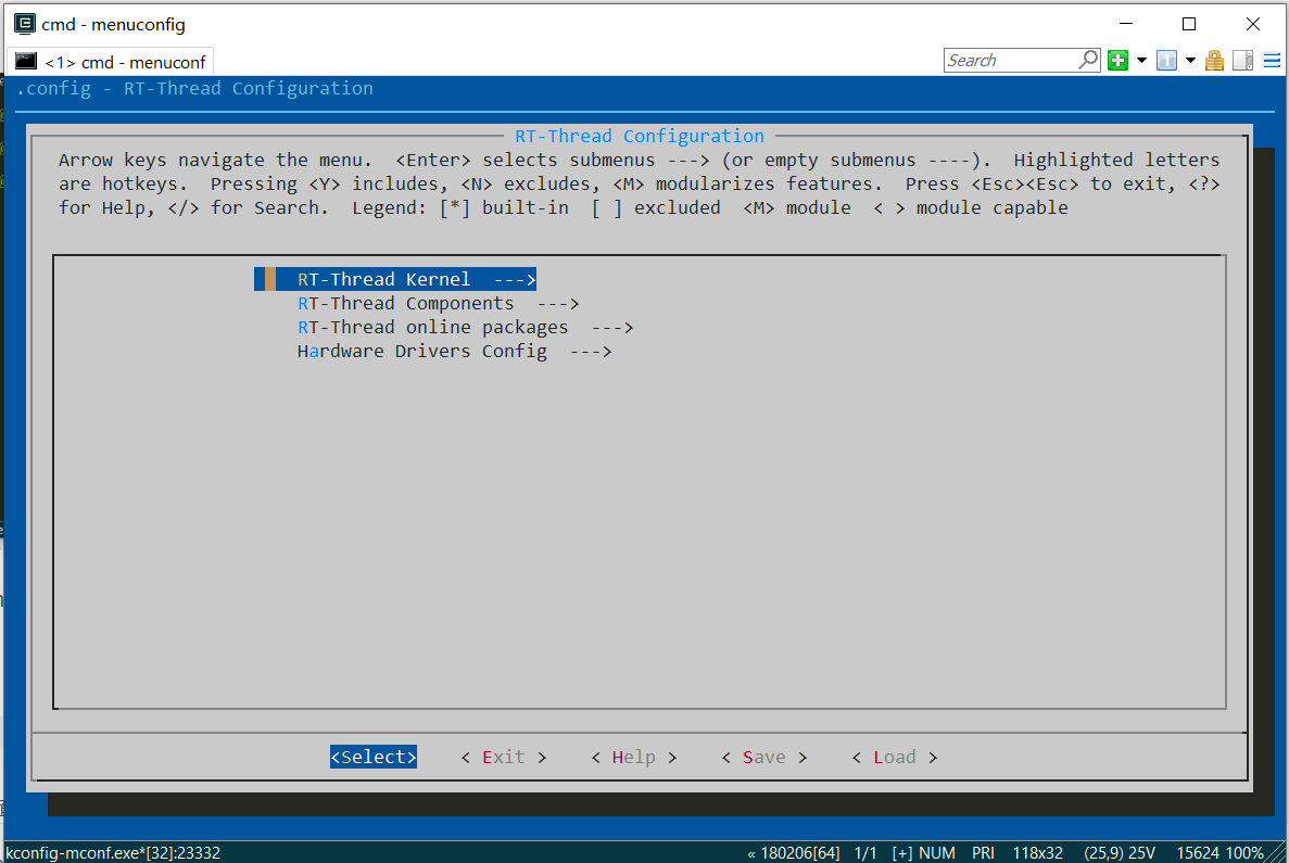
Press the up and down arrows on the keyboard to select the second item, RT thread components -- >, as shown in the following figure
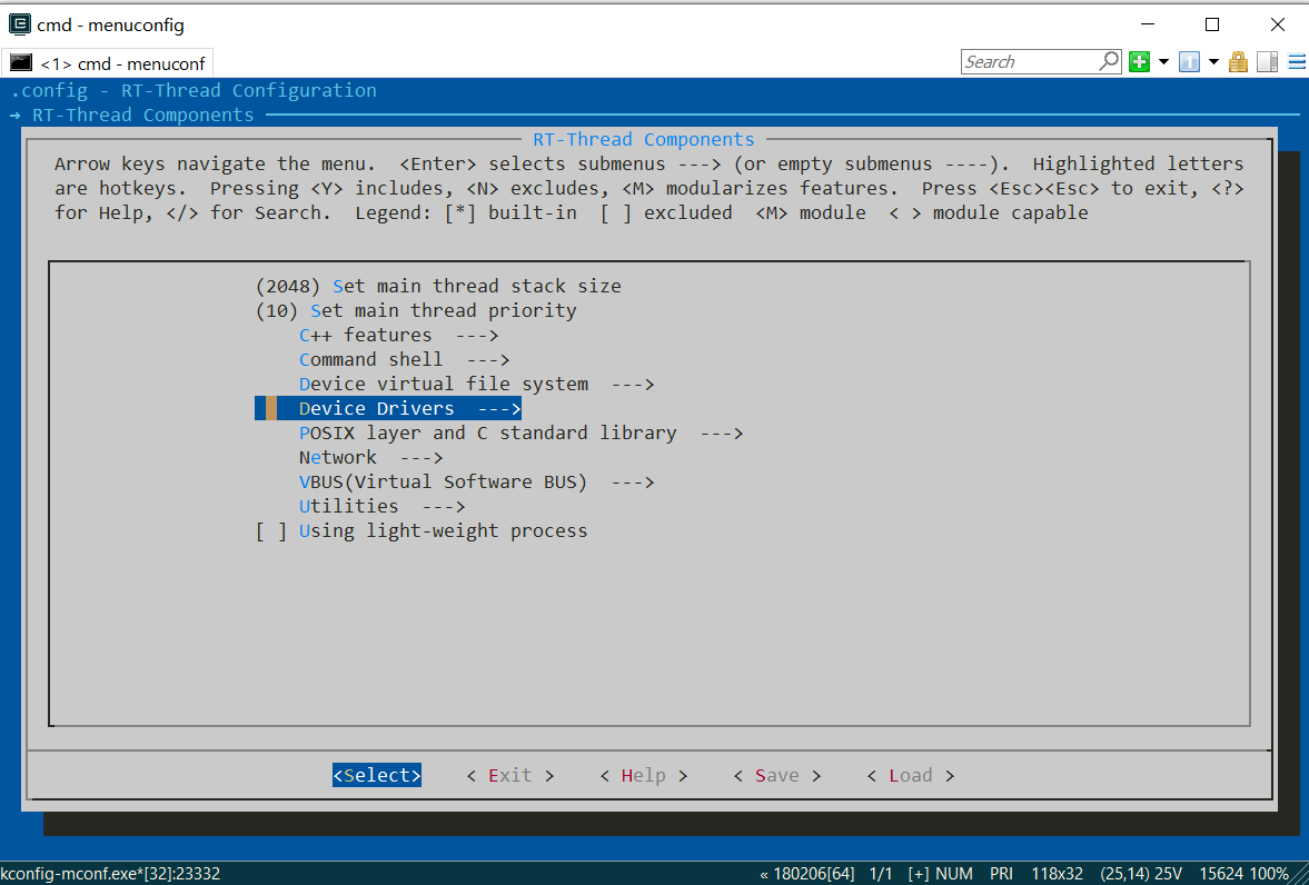
Press enter to enter. After entering, press the up and down arrows on the keyboard to select Device Drivers -- >, as shown in the following figure
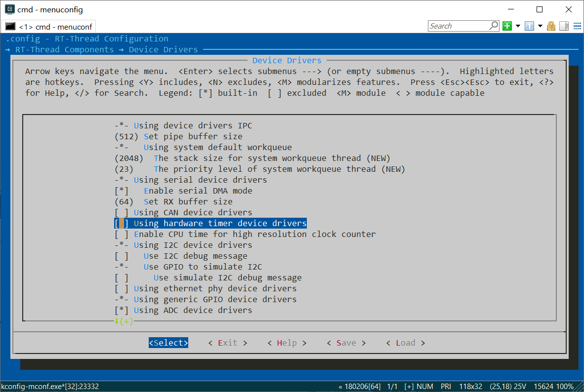
Press enter to enter. After entering, press the up and down arrows on the keyboard to select [] Using hardware timer device drivers, as shown in the following figure
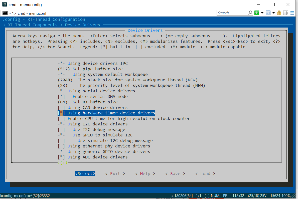
Press the Y key to enable this configuration, and * will appear in the square registration in front of the option. After enabling, it is shown in the figure below
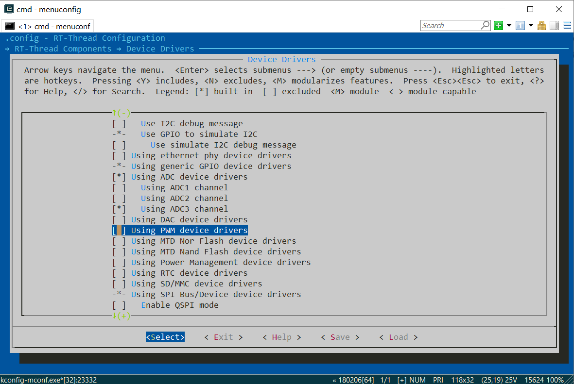
Continue to find the [] Using PWM device drivers option and enable it as above. As shown below:
Before enabling, you need to modify the Kconfig configuration file, which is in the rt-thread-4.0.3\components\drivers directory. The modification contents are as follows:
config RT_USING_PWM
    bool "Using PWM device drivers"
    default n
    if RT_USING_PWM
        config BSP_USING_PWM1
        bool "Using TIM1_PWM"
        default n

        if BSP_USING_PWM1
            config BSP_USING_PWM1_CH1
            bool "Using TIM1 PWM channel1"
            default n

            config BSP_USING_PWM1_CH2
            bool "Using TIM1 PWM channel1"
            default n

            config BSP_USING_PWM1_CH3
            bool "Using TIM1 PWM channel1"
            default n

            config BSP_USING_PWM1_CH4
            bool "Using TIM1 PWM channel1"
            default n
        endif

        config BSP_USING_PWM2
        bool "Using TIM2_PWM"
        default n

        if BSP_USING_PWM2
            config BSP_USING_PWM2_CH1
            bool "Using TIM2 PWM channel1"
            default n

            config BSP_USING_PWM2_CH2
            bool "Using TIM2 PWM channel2"
            default n

            config BSP_USING_PWM2_CH3
            bool "Using TIM2 PWM channel3"
            default n

            config BSP_USING_PWM2_CH4
            bool "Using TIM2 PWM channel4"
            default n
        endif

        config BSP_USING_PWM3
        bool "Using TIM3_PWM"
        default n

        if BSP_USING_PWM3
            config BSP_USING_PWM3_CH1
            bool "Using TIM3 PWM channel1"
            default n

            config BSP_USING_PWM3_CH2
            bool "Using TIM3 PWM channel2"
            default n

            config BSP_USING_PWM3_CH3
            bool "Using TIM3 PWM channel3"
            default n

            config BSP_USING_PWM3_CH4
            bool "Using TIM3 PWM channel4"
            default n
        endif

        config BSP_USING_PWM4
        bool "Using TIM4_PWM"
        default n

        if BSP_USING_PWM4
            config BSP_USING_PWM4_CH1
            bool "Using TIM4 PWM channel1"
            default n

            config BSP_USING_PWM4_CH2
            bool "Using TIM4 PWM channel2"
            default n

            config BSP_USING_PWM4_CH3
            bool "Using TIM4 PWM channel3"
            default n

            config BSP_USING_PWM4_CH4
            bool "Using TIM4 PWM channel4"
            default n
        endif

        config BSP_USING_PWM5
        bool "Using TIM5_PWM"
        default n

        if BSP_USING_PWM5
            config BSP_USING_PWM5_CH1
            bool "Using TIM5 PWM channel1"
            default n

            config BSP_USING_PWM5_CH2
            bool "Using TIM5 PWM channel2"
            default n

            config BSP_USING_PWM5_CH3
            bool "Using TIM5 PWM channel3"
            default n

            config BSP_USING_PWM5_CH4
            bool "Using TIM5 PWM channel4"
            default n
        endif
    endif
What is the specific meaning of the modified content in this paragraph? It is not explained here. If you want to know, you can search Baidu for relevant materials. This code is mainly used to realize the configuration of PWM function. After enabling, as shown in the figure below:
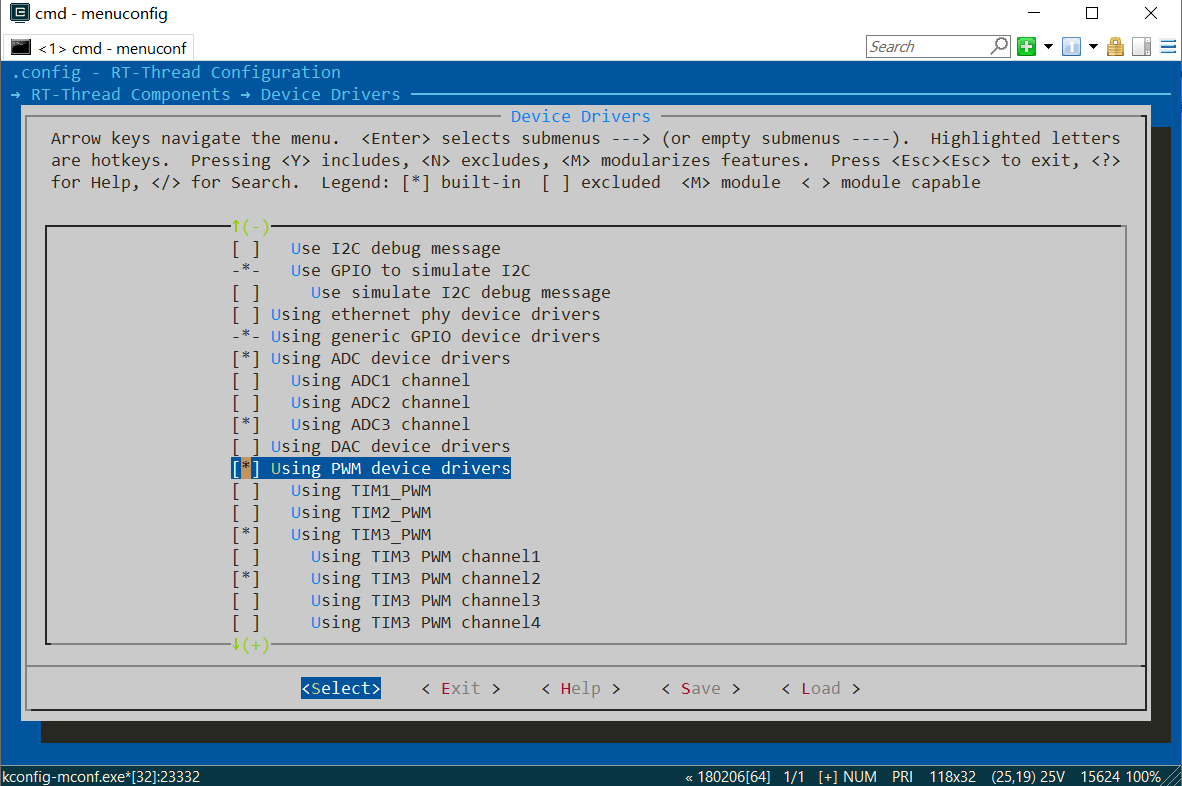
As can be seen from the figure, the PWM of} TIM3 is selected_ CH2 function. After configuration, press ESC key continuously to return to the following screen
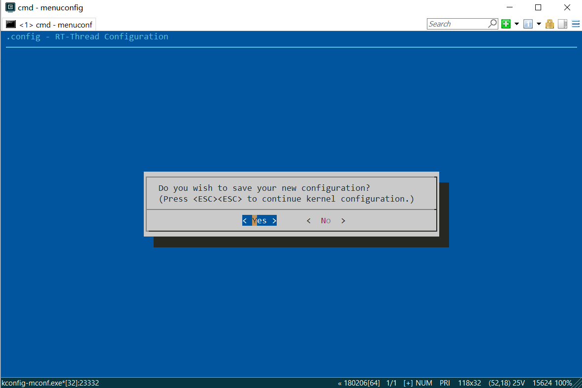
Press enter to exit the configuration screen.
Enter scons --target=mdk5 and press enter to regenerate the keil5 project.
Open the project and in the project stm32f1xx_hal_msp.c add the following code at the bottom:
void HAL_TIM_PWM_MspInit(TIM_HandleTypeDef* tim_pwmHandle)
{

  if(tim_pwmHandle->Instance==TIM3)
  {
  /* USER CODE BEGIN TIM3_MspInit 0 */

  /* USER CODE END TIM3_MspInit 0 */
    /* TIM3 clock enable */
    __HAL_RCC_TIM3_CLK_ENABLE();
  /* USER CODE BEGIN TIM3_MspInit 1 */

  /* USER CODE END TIM3_MspInit 1 */
  }
}
void HAL_TIM_MspPostInit(TIM_HandleTypeDef* timHandle)
{

  GPIO_InitTypeDef GPIO_InitStruct = {0};
  if(timHandle->Instance==TIM3)
  {
  /* USER CODE BEGIN TIM3_MspPostInit 0 */

  /* USER CODE END TIM3_MspPostInit 0 */

    __HAL_RCC_GPIOB_CLK_ENABLE();
    /**TIM3 GPIO Configuration
    PB5     ------> TIM3_CH2
    */
    GPIO_InitStruct.Pin = GPIO_PIN_5;
    GPIO_InitStruct.Mode = GPIO_MODE_AF_PP;
    GPIO_InitStruct.Speed = GPIO_SPEED_FREQ_LOW;
    HAL_GPIO_Init(GPIOB, &GPIO_InitStruct);

    __HAL_AFIO_REMAP_TIM3_PARTIAL();

  /* USER CODE BEGIN TIM3_MspPostInit 1 */

  /* USER CODE END TIM3_MspPostInit 1 */
  }

}

void HAL_TIM_PWM_MspDeInit(TIM_HandleTypeDef* tim_pwmHandle)
{

  if(tim_pwmHandle->Instance==TIM3)
  {
  /* USER CODE BEGIN TIM3_MspDeInit 0 */

  /* USER CODE END TIM3_MspDeInit 0 */
    /* Peripheral clock disable */
    __HAL_RCC_TIM3_CLK_DISABLE();
  /* USER CODE BEGIN TIM3_MspDeInit 1 */

  /* USER CODE END TIM3_MspDeInit 1 */
  }
}
This code is mainly used to initialize the PWM hardware function of PB5 pin. This code can be generated by STM32CubeMX. The generation method is solved by Baidu search.
Compile the project to test whether the device driver is added successfully. If there is no error in compilation, it means that the addition is successful. If there is an error in compilation, troubleshoot the problem according to the actual error. If you have any questions, you can contact me to help solve them.
Add the test code in the main program as follows:
int main(void)
{
        struct rt_device_pwm *pwm_dev;      /* PWM device handle  */
		static rt_uint32_t period, pulse;

		#define PWM_ DEV_ Name "pwm3" / * PWM device name*/
		#define PWM_ DEV_ Channel 2 / * PWM channel*/

		period = 500000;    /* The period is 0.5ms, and the unit is ns */
		pulse = 0;          /* PWM Pulse width value in nanoseconds ns */
		/* Find device */
		pwm_dev = (struct rt_device_pwm *)rt_device_find(PWM_DEV_NAME);
		/* Set PWM cycle and pulse width */
		rt_pwm_set(pwm_dev, PWM_DEV_CHANNEL, period, pulse);
		/* Enabling equipment */
		rt_pwm_enable(pwm_dev, PWM_DEV_CHANNEL);
//		/*Close the device channel*/
//		rt_pwm_disable(pwm_dev,PWM_DEV_CHANNEL);


	while (count++)
    {
    	pulse = pulse + 2000;
		if(pulse >= period) pulse = 0;
		rt_pwm_set(pwm_dev, PWM_DEV_CHANNEL, period, pulse);
        rt_thread_mdelay(10);
    }
    return RT_EOK;
}
After compilation, download it to the development board to observe the brightness adjustment effect of led3, as follows:
rtthread pwm adjusting led brightness