catalogue
I Review global variables, local variables, heap and stack under Ubuntu system and STM32.
1. Programming verification in Ubuntu (x86) system and STM32(Keil)
II Altium Designer 18 draws the system schematic design of an STM32+SD card
1. Installing Altium Designer 18
2. Draw the circuit schematic diagram of stm32 minimum system
(3) find the minimum version of STM32 in the newly added library
(4) crystal oscillator circuit
(7) download mode selection and program burning interface
(8) input and output power supply
(10) draw the system schematic diagram of SD card
(11) schematic diagram of STM32 + SD card
III Use STM32F103 to read the data of SD card (FAT file mode)
I Review global variables, local variables, heap and stack under Ubuntu system and STM32.
1. Programming verification in Ubuntu (x86) system and STM32(Keil)
(1) code writing
#include <stdio.h>
#include <stdlib.h>
//Define global variables
int init_global_a = 1;
int uninit_global_a;
static int inits_global_b = 2;
static int uninits_global_b;
void output(int a)
{
	printf("hello");
	printf("%d",a);
	printf("\n");
}

int main( )
{
	//Define local variables
	int a=2;//Stack
	static int inits_local_c=2, uninits_local_c;
    int init_local_d = 1;//Stack
    output(a);
    char *p;//Stack
    char str[10] = "yaoyao";//Stack
    //Define constant string
    char *var1 = "1234567890";
    char *var2 = "abcdefghij";
    //Dynamic allocation - heap area
    int *p1=malloc(4);
    int *p2=malloc(4);
    //release
    free(p1);
    free(p2);
    printf("Stack area-Variable address\n");
    printf("                a : %p\n", &a);
    printf("                init_local_d: %p\n", &init_local_d);
    printf("                p: %p\n", &p);
    printf("              str: %p\n", str);
    printf("\n Heap area-Dynamic application address\n");
    printf("                   %p\n", p1);
    printf("                   %p\n", p2);
    printf("\n Global area-Global and static variables\n");
    printf("\n.bss paragraph\n");
    printf("Global external no initial value uninit_global_a: %p\n", &uninit_global_a);
    printf("Static external no initial value uninits_global_b: %p\n", &uninits_global_b);
    printf("Static internal no initial value uninits_local_c: %p\n", &uninits_local_c);
    printf("\n.data paragraph\n");
    printf("Global external initial value init_global_a: %p\n", &init_global_a);
    printf("Static external initial value inits_global_b: %p\n", &inits_global_b);
    printf("Static internal initial value inits_local_c: %p\n", &inits_local_c);
    printf("\n Text constant area\n");
    printf("Literal constant address     : %p\n",var1);
    printf("Literal constant address     : %p\n",var2);
    printf("\n Code area\n");
    printf("Program area address       : %p\n",&main);
    printf("Function address         : %p\n",&output);
    return 0;
}
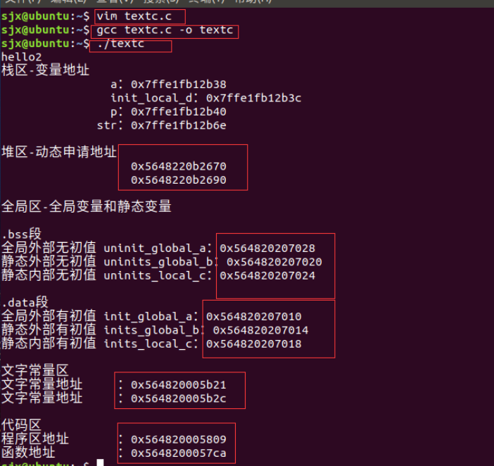
(2)ubuntu operation
- First, vim C Documents
- Compile and generate gcc o documentation
- Run executable
(3)stm(keil) operation
cubemx establish serial port program

Modify main function
#include "main.h"
#include "usart.h"
#include "gpio.h"
#include <stdio.h>
#include <stdlib.h>
//Define global variables
int init_global_a = 1;
int uninit_global_a;
static int inits_global_b = 2;
static int uninits_global_b;
void output(int a)
{
printf("hello");
printf("%d",a);
printf("\n");
}
/* Private includes ----------------------------------------------------------*/
/* USER CODE BEGIN Includes */
/* USER CODE END Includes */
/* Private typedef -----------------------------------------------------------*/
/* USER CODE BEGIN PTD */
/* USER CODE END PTD */
/* Private define ------------------------------------------------------------*/
/* USER CODE BEGIN PD */
/* USER CODE END PD */
/* Private macro -------------------------------------------------------------*/
/* USER CODE BEGIN PM */
/* USER CODE END PM */
/* Private variables ---------------------------------------------------------*/
/* USER CODE BEGIN PV */
/* USER CODE END PV */
/* Private function prototypes -----------------------------------------------*/
void SystemClock_Config(void);
/* USER CODE BEGIN PFP */
/* USER CODE END PFP */
/* Private user code ---------------------------------------------------------*/
/* USER CODE BEGIN 0 */
/* USER CODE END 0 */
/**
* @brief The application entry point.
* @retval int
*/
int main(void)
{
/* USER CODE BEGIN 1 */
/* USER CODE END 1 */
/* MCU Configuration--------------------------------------------------------*/
/* Reset of all peripherals, Initializes the Flash interface and the Systick. */
HAL_Init();
/* USER CODE BEGIN Init */
/* USER CODE END Init */
/* Configure the system clock */
SystemClock_Config();
/* USER CODE BEGIN SysInit */
/* USER CODE END SysInit */
/* Initialize all configured peripherals */
MX_GPIO_Init();
MX_USART1_UART_Init();
/* USER CODE BEGIN 2 */
/* USER CODE END 2 */
/* Infinite loop */
/* USER CODE BEGIN WHILE */
int a=2;
static int inits_local_c=2, uninits_local_c;
int init_local_d = 1;
output(a);
char *p;
char str[10] = "lyy";
//Define constant string
char *var1 = "1234567890";
char *var2 = "qwertyuiop";
//Dynamic allocation
int *p1=malloc(4);
int *p2=malloc(4);
//release
free(p1);
free(p2);
printf("Stack area-Variable address\n");
printf(" a: %p\n", &a);
printf(" init_local_d: %p\n", &init_local_d);
printf(" p: %p\n", &p);
printf(" str: %p\n", str);
printf("\n Heap area-Dynamic application address\n");
printf(" %p\n", p1);
printf(" %p\n", p2);
printf("\n Global area-Global and static variables\n");
printf("\n.bss paragraph\n");
printf("Global external no initial value uninit_global_a: %p\n", &uninit_global_a);
printf("Static external no initial value uninits_global_b: %p\n", &uninits_global_b);
printf("Static internal no initial value uninits_local_c: %p\n", &uninits_local_c);
printf("\n.data paragraph\n");
printf("Global external initial value init_global_a: %p\n", &init_global_a);
printf("Static external initial value inits_global_b: %p\n", &inits_global_b);
printf("Static internal initial value inits_local_c: %p\n", &inits_local_c);
printf("\n Text constant area\n");
printf("Literal constant address : %p\n",var1);
printf("Literal constant address : %p\n",var2);
printf("\n Code area\n");
printf("Program area address : %p\n",&main);
printf("Function address : %p\n",&output);
return 0;
/* USER CODE END 3 */
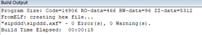
}Compile
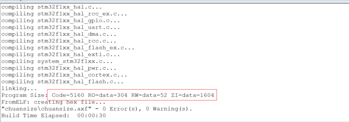
After compilation, we can see that there are four Code segment sizes: Code, RO data, RW data and Zi data
Where Code is the Code occupation size, RO data is a read-only constant, RW data is an initialized readable and writable variable, and Zi data is an uninitialized readable and writable variable.
Sometimes, we need to know how RAM and ROM are used, so we can use the following formula to calculate.
RAM = RW-data + ZI-data
ROM = Code + RO-data + RW-data
Flash=Code + RO Data + RW Data
This is the size of each segment that can be obtained after MDK compilation, and the corresponding FLASH and RAM size can be obtained. However, there are two data segments that will also occupy RAM, but only when the program is running, that is, heap and stack.
Operation results
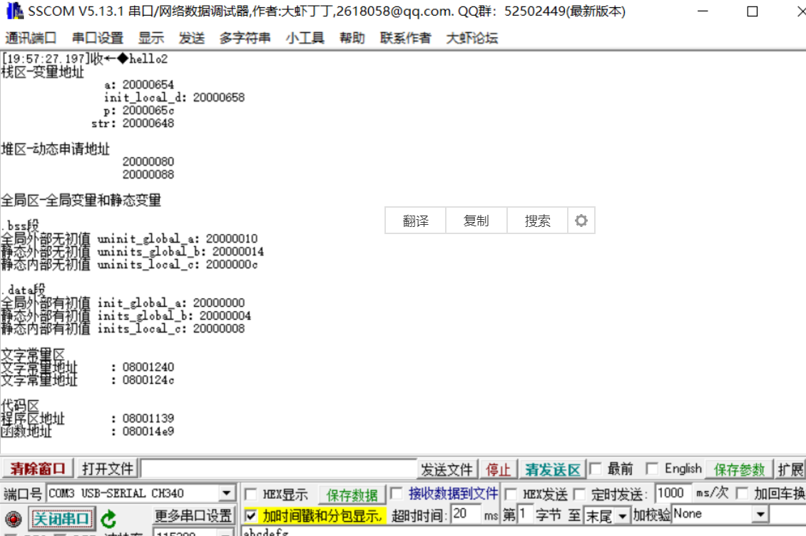
Through the running results, it can be found that the address values of Ubuntu in the stack area and heap area increase from top to bottom, the address values of raspberry pie and stm32 stack area decrease from top to bottom, and the heap area increases from top to bottom. From each area, the address value decreases gradually from top to bottom, that is, the address of the stack area is the high address and the address of the code area is the low address.
View stm32 address assignment

It can be seen from the picture that the address allocation of ROM starts from 0x8000000 and the whole size is 0x10000. This part is used to store the code area and text constant area. The address allocation of RAM starts from 0x20000000 and its size is 0x5000. This area is used to store stack, heap and global area (. bss segment and. data segment). Compared with the code result display, it can also be seen that the address of the corresponding part corresponds to the setting.
II Altium Designer 18 draws the system schematic design of an STM32+SD card
1. Installing Altium Designer 18
Install network disk link:
Link: https://pan.baidu.com/s/1VekZO_P_R3tXxAYR2BXf3A
Extraction code: qwer
2. Draw the circuit schematic diagram of stm32 minimum system
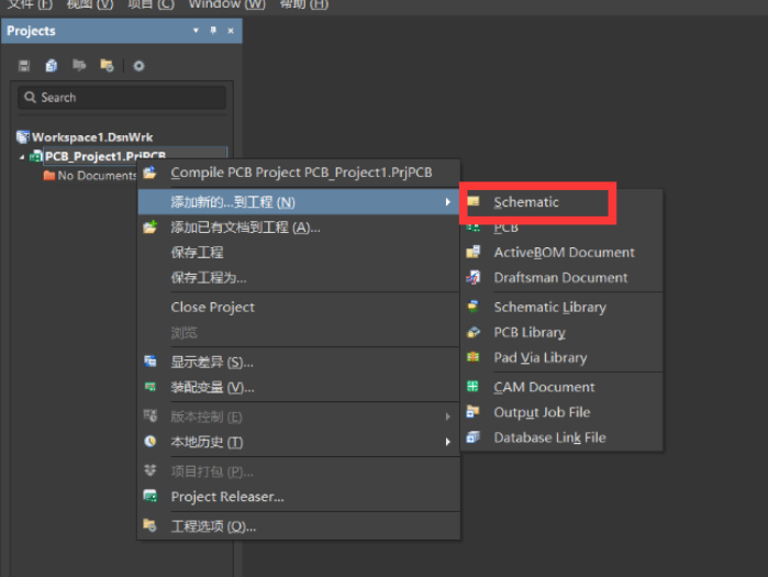
(1) new construction
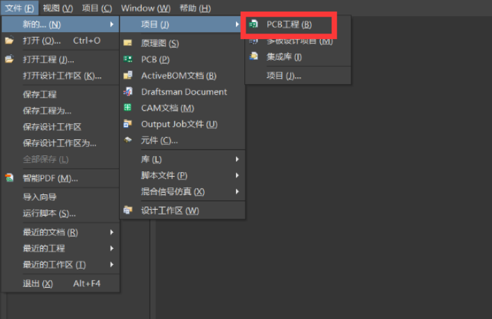
Add a Schematic to the new project
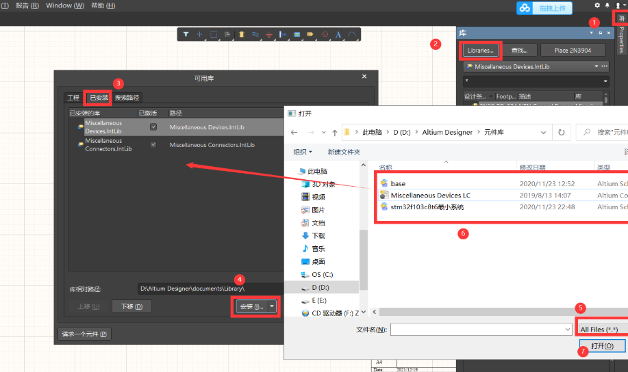
(2) add catalog
Link: https://pan.baidu.com/s/1osAgInCxJ6OZFpT2p9PHkw
Extraction code: qwer
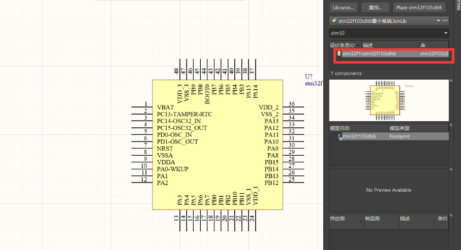
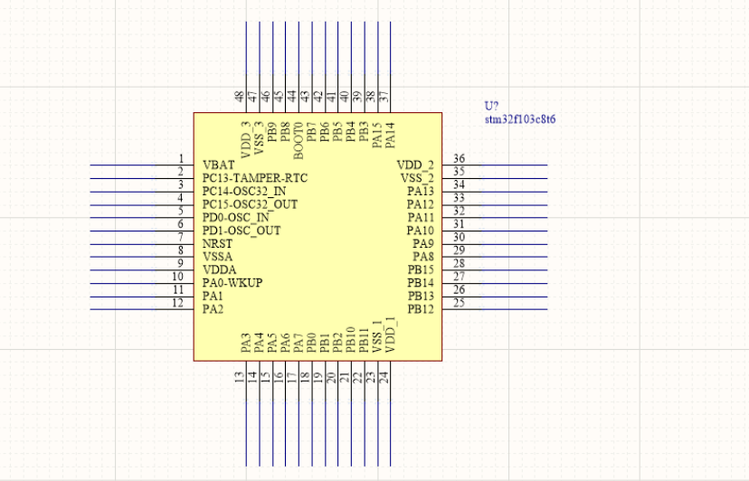
(3) find the minimum version of STM32 in the newly added library

Drag the module out
(4) extension pin
Click the extension pin, click at the original position and then at the end, and then esc can be performed
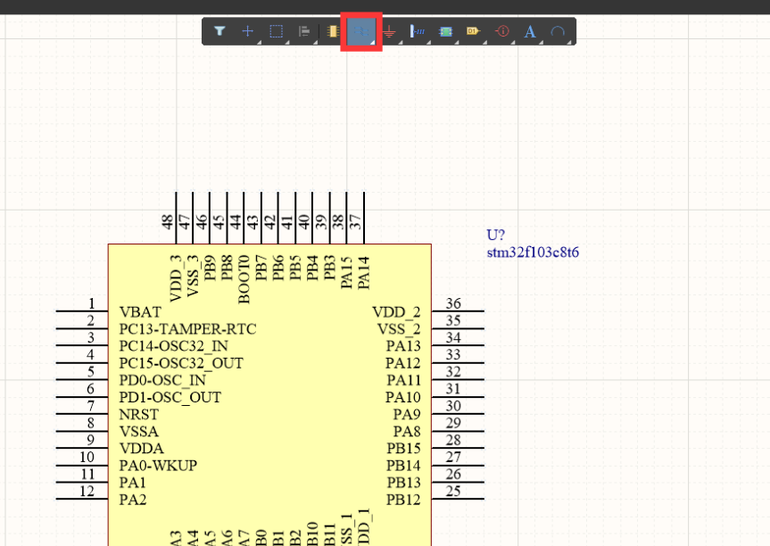
The results are shown in the figure
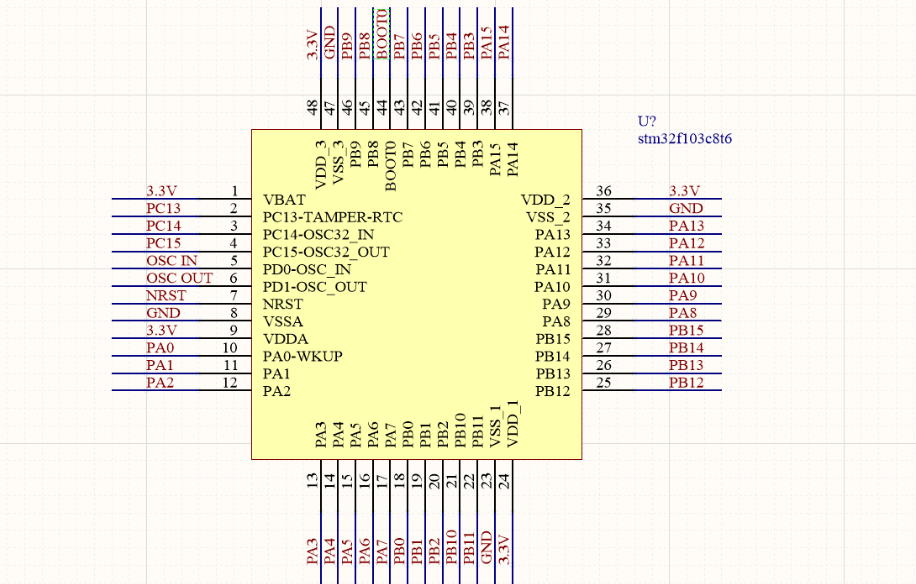
(5) set grid number
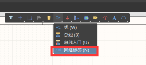
After clicking, the component will hang on the mouse. At this time, do not place it first. Press tab to enter the setting window, edit the number and name, then press enter to exit the editing box, and then left click to put it down. When a network tag is placed, the value of the next tag will be automatically added by one. It is convenient for us to label instead of one by one

Final results
3. Draw results
(1) basic search

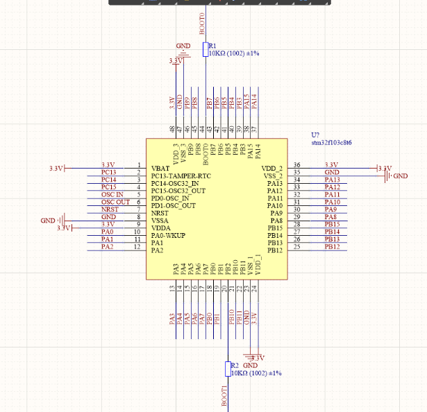
 (2)STM32 chip
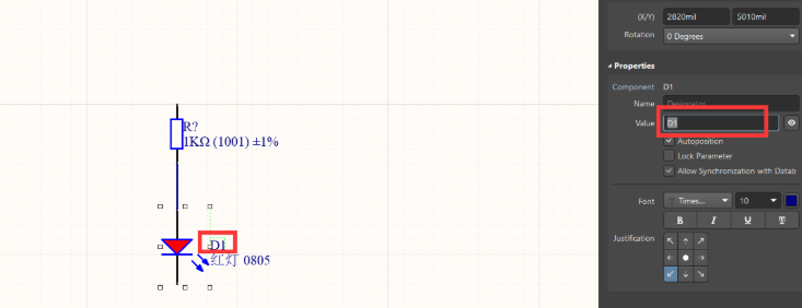
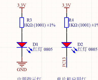
Add resistance to the original
R: Miscellaneous Devices LC. Search for 0805 1k in IntLib catalog
R: Miscellaneous Devices LC. Search for 0805 1k in IntLib catalog
D: Miscellaneous Devices LC. Search for 0805 red in IntLib catalog
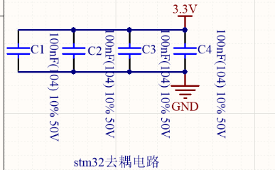
(3)stm32 decoupling circuit
C: Miscellaneous Devices LC. Search for 0805 100nf in IntLib catalog
(4) crystal oscillator circuit
Y: Miscellaneous Devices. Search for XTAL in IntLib catalog
C: Miscellaneous Devices LC. Search for 0805 22pf in IntLib catalog

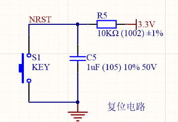
(5) reset circuit
S: Miscellaneous Devices. Search for SW Pb in IntLib catalog
C: Miscellaneous Devices LC. Search for 0805 1uf in IntLib catalog
(6) step down circuit
AMS1117: stm32f103c8t6 minimum system In SchLib catalog

The LDO(Low Dropout Regulator) low dropout linear regulator converts 5V to 3.3V and supplies power to the main control chip.
(7) download mode selection and program burning interface
P: Miscellaneous Connectors. Search for MHDR2X3 in IntLib catalog
P: Miscellaneous Connectors. Search for MHDR1X4 in IntLib catalog
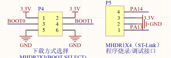
In the process of program development, you need to download bin/hex files and online simulation debugging. SWD or JTAG can be used. SWD mode is more reliable than JTAG in high-speed mode, and only needs 4 pins. SWD mode is generally used in actual development. The clock line CLK is used for clock synchronization between Jlink and the chip. The general frequency is set to 4MHz, and the frequency can be adjusted according to the actual situation.
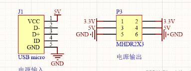
(8) input and output power supply
J: base. Search for USB micro in schlib catalog
(9) needle arrangement
P: Miscellaneous Connectors. Search for MHDR1X16 in IntLib catalog
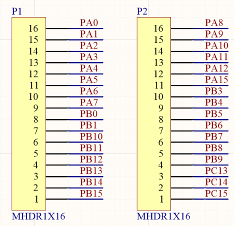
After drawing, add labels. For the schematic diagram just completed, the labels of each component are letters +?, At this time, we can add annotations with one click.

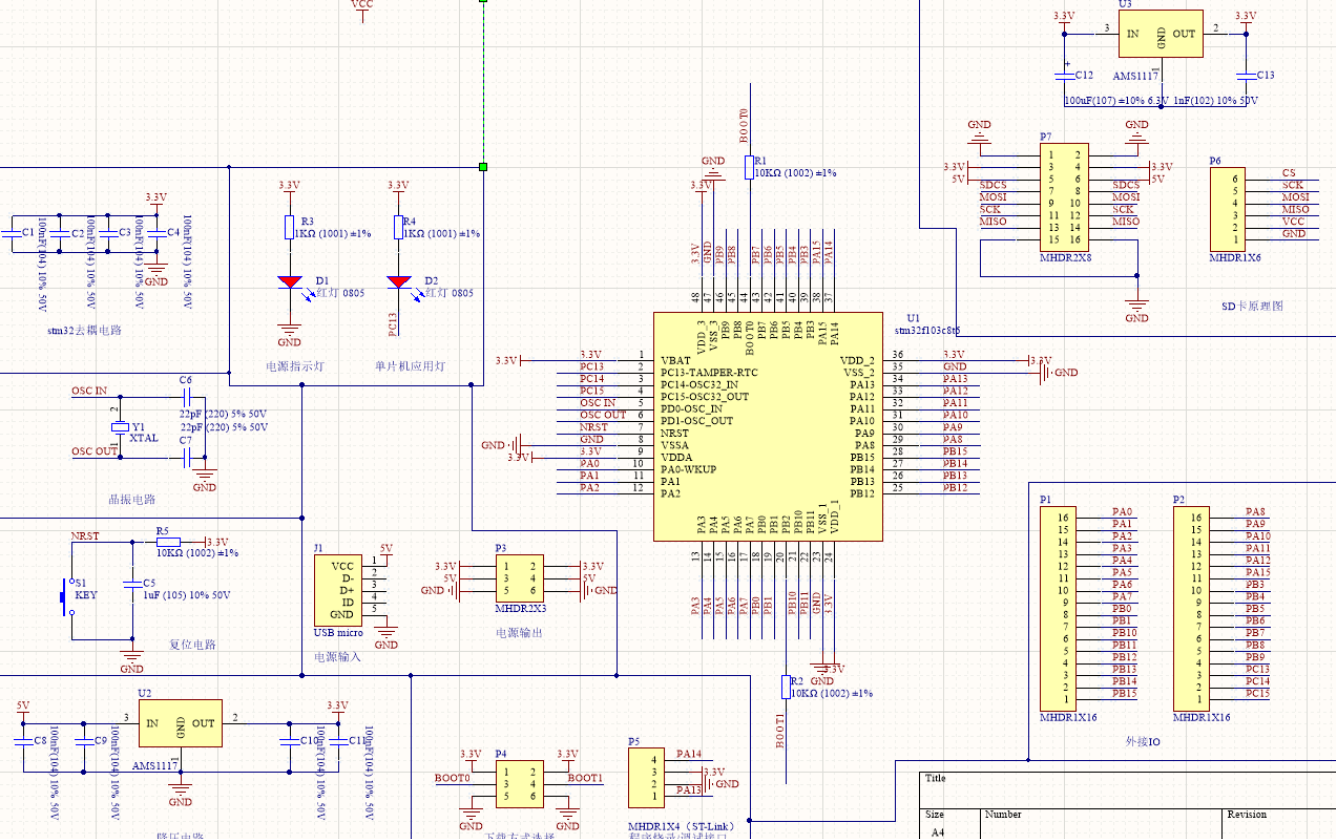
(10) draw the system schematic diagram of SD card

(11) schematic diagram of STM32 + SD card
III Use STM32F103 to read the data of SD card (FAT file mode)
1. Source download
github Download: GitHub - cdsgsjx/-
2. Operation steps
(1) formatting
First, insert the SD card into the computer and format it manually to FAT format
(2) connection operation
| STM32 | SD card |
|---|---|
| CS | PA4 |
| SCK | PA5 |
| MISO | PA6 |
| MOSI | PA7 |
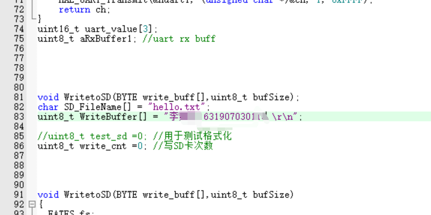
(3) Code modification
main.c
while loop
while (1)
  {


		WritetoSD(WriteBuffer,sizeof(WriteBuffer));


		HAL_Delay(500);
		/*WriteBuffer[0] = WriteBuffer[0] +10;
		WriteBuffer[1] = WriteBuffer[1] +10;*/
		write_cnt ++;

		while(write_cnt > 0)
		{
			printf(" while \r\n");
			HAL_Delay(500);
		}
3. Compile run
4. Burning operation results
There are two successful initialization replies. The first is when the memory is used and format is selected, and the second is when the SD card is written
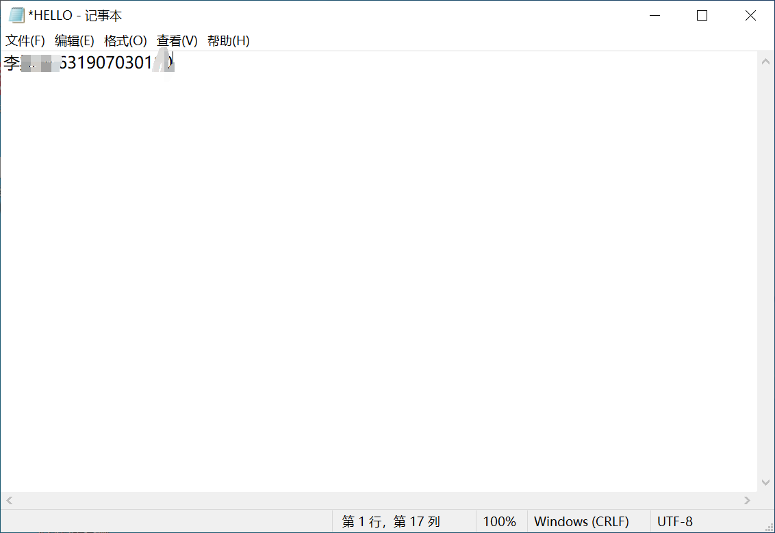
You can see that a total of 22 bytes are output, \ r\n indicating carriage return and line feed.