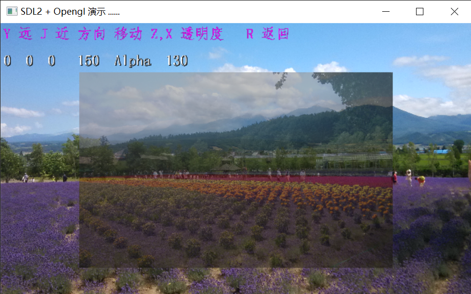
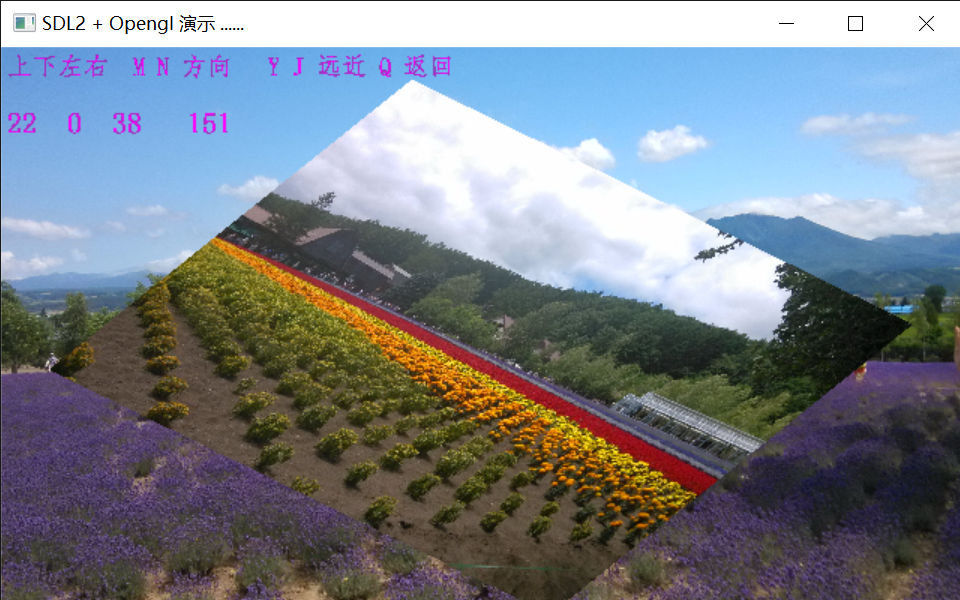
The content of this article includes: the implementation of freetype Chinese character display, the use of GLSL, including the use skills of slice shader, texture mixing, transparent display method, texture sampling method, etc., vertex shader, common transformation skills, image enlargement, image reduction, image rotation, etc
Continued:
1, How to add Chinese characters in SDL2
SDL has no text display function. To display text, you must graphically convert the text into graphics, and then display it through the graphics display function. The same is true for OpenGL. There are many ways to generate text graphics. SDL itself also provides a special module, which first converts text into SDL graphic surface, and then displays it. This is SDL TTF. This module actually calls another set of sharing software freetype, and OpenGL has similar applications. I studied it. I don't know why. SDL TTF seems to be deleted from the SDL official website. According to the guidelines of the official website, the source programs from github can't be used. But I had to use freetype. Fortunately, there are examples of freetype for reference, There are many related materials on the Internet. Freetype itself has no display function. It can only form a font cache structure, import OpenGL or SDL texture, render the text into the frame cache through the texture, and then display the text on the screen through the frame cache. The process of adding font cache to texture is quite slow, so in the process of program processing, generally, the font to be displayed will be written into texture cache in advance, and then enter the rendering cycle, and the texture will be used for display when necessary. Because the texture is processed concurrently using video memory and GPU, the processing speed is quite fast. I have tested that a rendering including nearly 100 steps only takes a few milliseconds. The same process, if the text is processed in real time, will take more than ten times as long as before.
You can also make the text to be displayed into a BMP file in advance, and the part is like this:
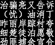
When in use, the font image is loaded in advance to generate texture. If the file is 1024 * 1024 in size, 4096 32 * 32 Chinese characters and other symbols or 16384 16 * 16 Chinese characters can be saved, which is enough for daily display. The advantage of this is that it can display text perfectly without special word processing process. Of course, this requires a dictionary to be generated in advance.
However, in the process of human-computer interaction, when you need to temporarily input the words that are not displayed, you can also insert the words that are not in the input dictionary into the dictionary and copy them into the texture one by one, because the display speed of milliseconds is not required during human-computer interaction.
The following is a page that displays text
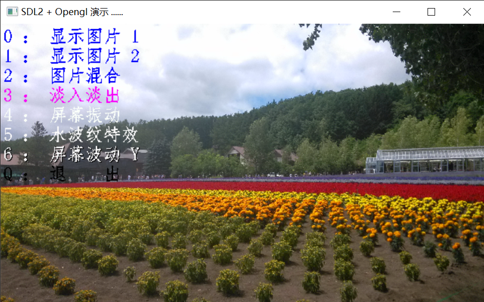
Here are the relevant codes:
map <WCHAR, int > FontMap;
const int  HZSIZE = 32;
const int  ASCIISIZE = 32;
const int  TextBufSize = 32;

int GL_Render::FontInit(string path, INT  isBIG5)
{
    //Function initialization font texture
    //Enter the directory where the game files are located
    FT_Library library;
    if (FT_Init_FreeType(&library))
        return 1;
    FT_Face       face;
    if (FT_New_Face(library, "c:/windows/fonts/simfang.ttf", 0, &face))
    {
        FT_Done_FreeType(library);
        return 1;
    }

    //The following initializes the font texture
    VOID* gp_TextBuf = NULL;

    FILE* fp;
    string m_path = path + "wor16.asc";
    if ((fopen_s(&fp, m_path.c_str(), "rb")))
        return -1;
    fseek(fp, 0, SEEK_END);
    int nChar = ftell(fp);
    nChar /= 2;
    fseek(fp, 0, SEEK_SET);
    LPWORD charbuf = new WORD[(INT64)nChar + 10];
    if (charbuf == nullptr)
        exit(1);
    fread(charbuf, sizeof(WORD), nChar, fp);

    //Create texture, cache and store font
    if (TextBufSize == 8)
    {
        gp_TextBuf = new char[(size_t)HZSIZE * 64 * ((size_t)nChar / 64 + 1) * HZSIZE];
        memset(gp_TextBuf, 0, (size_t)HZSIZE * 64 * ((size_t)nChar / 64 + 1) * HZSIZE * sizeof(GLubyte));
    }
    else
    {
        gp_TextBuf = new INT32*[(size_t)HZSIZE * 64 * ((size_t)nChar / 64 + 1) * HZSIZE];
        memset(gp_TextBuf, 0, (size_t)HZSIZE * 64 * ((size_t)nChar / 64 + 1) * HZSIZE * sizeof(INT32));
    }
    FT_Set_Pixel_Sizes(face, 0, HZSIZE);

    for (int n = 0; n < nChar; n++)
    {
        char s[3];
        WORD w = charbuf[n];
        WCHAR wstr[2];
        wchar_t rewstr[2];
        s[2] = 0;
        s[0] = w & 0xff;
        s[1] = w >> 8;
        if (isBIG5)
        {
            MultiByteToWideChar(950, 0, s, -1, wstr, 1);
            //Convert to simplified characters
            WORD wLCID = MAKELCID(MAKELANGID(LANG_CHINESE, SUBLANG_CHINESE_SIMPLIFIED), SORT_CHINESE_BIG5);
            LCMapString(wLCID, LCMAP_SIMPLIFIED_CHINESE, wstr, 1, rewstr, 1);
        }
        else
            MultiByteToWideChar(936, 0, s, -1, rewstr, 1);

        FontMap.insert(pair<WCHAR, INT>(rewstr[0], n));

        rewstr[1] = 0;
        size_t cx = (n & 63) * HZSIZE;
        size_t cy = (n >> 6) * HZSIZE;
        FT_Load_Char(face, rewstr[0], FT_LOAD_RENDER | FT_LOAD_TARGET_NORMAL);
        FT_GlyphSlot  slot = face->glyph;
        int xOff = slot->bitmap_left;
        int yOff = (face->size->metrics.ascender >> 6) - slot->bitmap_top;
        if (TextBufSize == 8)
            ConvertSlotToBuf(&slot->bitmap, (GLubyte*)gp_TextBuf, HZSIZE * 64,
                cx  + xOff, cy  + (yOff));
        else
            ConvertSlotToBuf32(&slot->bitmap, (INT32*)gp_TextBuf, HZSIZE * 64,
                cx  + xOff, cy  + (yOff));
    }
    //Copy to texture
    SDL_Surface* fontsurf;
    if (TextBufSize == 8)
        fontsurf = SDL_CreateRGBSurfaceWithFormatFrom(gp_TextBuf, HZSIZE * 64,
            (nChar / 64 + 1) * HZSIZE, 8,
            HZSIZE * 64, SDL_PIXELFORMAT_RGB332);
    else
        fontsurf = SDL_CreateRGBSurfaceWithFormatFrom(gp_TextBuf, HZSIZE * 64,
            (nChar / 64 + 1) * HZSIZE, 32,
            HZSIZE * 64 * sizeof(INT32), SDL_PIXELFORMAT_RGBA8888);
    //Save character map
    //SDL_SaveBMP(fontsurf, "fontt.bmp");
    gpFontTexture = SDL_CreateTextureFromSurface(gpSdlRender,fontsurf);
    SDL_FreeSurface(fontsurf);
    delete[]gp_TextBuf;
    delete [] charbuf;
    if (TextBufSize == 8)
    {
        gp_TextBuf = new char[ASCIISIZE * 60 * ASCIISIZE];
        memset(gp_TextBuf, 0, ASCIISIZE * 60 * ASCIISIZE);
    }
    else
    {
        gp_TextBuf = new INT32[ASCIISIZE * 60 * ASCIISIZE];
        memset(gp_TextBuf, 0, ASCIISIZE * 60 * ASCIISIZE * sizeof(INT32));
    }

    FT_Set_Pixel_Sizes(face, 0, ASCIISIZE);

    //Print ascII characters
    for (int n = 0; n < 96; n++)
    {
        WCHAR s[2];
        s[1] = 0;
        s[0] = n + 32;//From space to 126
        size_t cx = n * ASCIISIZE / 2;
        //FT_Load_Char(face, s[0], FT_LOAD_RENDER | FT_LOAD_MONOCHROME);
        //FT_Load_Char(face, s[0], FT_LOAD_RENDER|FT_LOAD_TARGET_NORMAL| FT_LOAD_FORCE_AUTOHINT);
        //FT_Load_Char(face, s[0], FT_LOAD_RENDER| FT_LOAD_TARGET_MONO);
        //FT_Load_Char(face, s[0], FT_LOAD_RENDER| FT_LOAD_DEFAULT);
        FT_Load_Char(face, s[0], FT_LOAD_RENDER);

        FT_GlyphSlot  slot = face->glyph;
        int xOff = slot->bitmap_left;
        int yOff = (face->size->metrics.ascender >> 6) - slot->bitmap_top;
        ConvertSlotToBuf32(&slot->bitmap, (INT32*)gp_TextBuf, ASCIISIZE * 48, cx + xOff, (yOff));
    }
    SDL_Surface* asciiSurf;
    if(TextBufSize == 8)
    asciiSurf = SDL_CreateRGBSurfaceWithFormatFrom(gp_TextBuf, ASCIISIZE * 48, ASCIISIZE,
        8, ASCIISIZE * 48, SDL_PIXELFORMAT_RGB332);
    else
        asciiSurf = SDL_CreateRGBSurfaceWithFormatFrom(gp_TextBuf, ASCIISIZE * 48, ASCIISIZE,
            8, ASCIISIZE * 48 * sizeof(INT32), SDL_PIXELFORMAT_RGBA8888);
    //Save character map
    //SDL_SaveBMP(asciiSurf, "ascII.bmp");
    gpASCIITexture = SDL_CreateTextureFromSurface(gpSdlRender, asciiSurf);
    SDL_FreeSurface(asciiSurf);

    //clear
    delete[] gp_TextBuf;
    fclose(fp);
    //
    FT_Done_Face(face);
    FT_Done_FreeType(library);

    return 0;
}

//Target is 8byte
//Input: source font structure, target cache, target row byte, target row displacement, target column displacement
//Return: 0 succeeded, others failed
int GL_Render::ConvertSlotToBuf(FT_Bitmap* srcSlot, GLubyte* dstBuf,int dstPitch, int xPos, int yPos)
{
    if (srcSlot == NULL || dstBuf == NULL)
        return -1;
    if (xPos + srcSlot->width > dstPitch)
        return -1;
    for (int y = 0; y < srcSlot->rows; y++)
    {
        GLubyte* dstP = dstBuf + (static_cast<__int64>(yPos) + y) * dstPitch + xPos;
        GLubyte* srcP = srcSlot->buffer + static_cast<__int64>(y) * srcSlot->pitch;
        for (int x = 0; x < srcSlot->width; x++)
        {
            if (srcSlot->pixel_mode == 1)
            {
                //The source is 1 byte
                dstP[x] = ((1 << (7 - (x & 7))) & srcP[(x >> 3)]) ? 255 : 0;
            }
            else
            {
                //Source is 8byte
                dstP[x] = srcP[x];
                //dstP[x] = srcP[x] ? 255 : 0;
            }
        }
    }
    return 0;
}

//The target is a 32-bit cache
//Input: source font structure, target cache, target row byte, target row displacement, target column displacement
//Return: 0 succeeded, others failed
int GL_Render::ConvertSlotToBuf32(FT_Bitmap* srcSlot, INT32* dstBuf, int dstPitch, int xPos, int yPos)
{
    if (srcSlot == NULL || dstBuf == NULL)
        return -1;
    if (xPos + srcSlot->width > dstPitch)
        return -1;
    for (int y = 0; y < srcSlot->rows; y++)
    {
        INT32 * dstP = dstBuf + (static_cast<__int64>(yPos) + y) * dstPitch + xPos;
        GLubyte* srcP = srcSlot->buffer + static_cast<__int64>(y) * srcSlot->pitch;
        for (int x = 0; x < srcSlot->width; x++)
        {
            if (srcSlot->pixel_mode == 1)
            {
                //The source is 1 byte
                dstP[x] = ((1 << (7 - (x & 7))) & srcP[(x >> 3)]) ? 0xffffffff : 0;
            }
            else
            {
                //Source is 8byte
                dstP[x] = srcP[x] ? 0xffffff | srcP[x] << 24 : 0;
            }
        }
    }
    return 0;
}


SIZE GL_Render::DrawWideText(LPCWSTR lpszTextR, _POS pos, SDL_Color bColor, BOOL fShadow, BOOL fUpdate, int size)
{
    //Function: print wide string on screen
    //Return: occupied screen size
    int cx = POS_X(pos) * PictureRatio;
    int cy = POS_Y(pos) * PictureRatio;

    int len = lstrlenW(lpszTextR);
    size *= PictureRatio;
    SIZE wsz = { 0,size };
    SIZE zsz = { size,size };
    SDL_Rect srcRect;
    SDL_Rect dstRect;
    SDL_Texture* srcTexture;
    for (int n = 0; n < len; n++)
    {
        if (isascii(lpszTextR[n]))
        {
            if (lpszTextR[n] < 32)
                continue;
            zsz = { size / 2,size };
            srcTexture = gpASCIITexture;
            srcRect = { (lpszTextR[n] - 32) * ASCIISIZE / 2,0,ASCIISIZE / 2,ASCIISIZE };
            dstRect = { cx,cy,zsz.cx,zsz.cy };
            cx += zsz.cx;
            wsz.cx += zsz.cx;
        }
        else
        {
            zsz = { size,size };
            srcTexture = gpFontTexture;
            WCHAR s = lpszTextR[n];
            map<WCHAR, INT> ::iterator iter;
            iter = FontMap.find(s);
            if (iter == FontMap.end())
                //no find
                continue;
            int off = iter->second;
            srcRect = { (off & 63) * HZSIZE,(off >> 6) * HZSIZE,HZSIZE,HZSIZE };
            dstRect = { cx,cy,zsz.cx,zsz.cy };
            cx += zsz.cx;
            wsz.cx += zsz.cx;
        }
        if (fShadow)
        {
            SDL_Color mColor = { 2,2,2,0 };
            SDL_Rect mdstRect = dstRect;
            mdstRect.x++;
            RenderBlendCopy(gpRenderTexture, srcTexture, nullptr, 255, 6,
                &mColor, &mdstRect, &srcRect);
            mdstRect.y++;
            RenderBlendCopy(gpRenderTexture, srcTexture, nullptr, 255, 6,
                &mColor, &mdstRect, &srcRect);
        }
        if (bColor.r == 0 && bColor.g == 0 && bColor.b == 0)
            bColor = { 4,4,4,128 };
        RenderBlendCopy(gpRenderTexture, srcTexture, nullptr, 255, 6,
            &bColor, &dstRect, &srcRect);
    }
    if (fUpdate)
    {
        RenderPresent(gpRenderTexture);
    }
    return wsz;
}
II. GLSL application
Let's first talk about the slice shader, also known as the fragment shader. The slice shader performs the last stage of the rendering process. The goal is to determine the color of each specific pixel reflected in the final calculation. This process is carried out concurrently, that is, GPU calculates many pixels in parallel at one time, and the order of calculating pixels is uncertain, so in the whole calculation process, Each original texture is read-only. Although the latest version of OpenGL can support texture modification, it is conditional. The read (sample) point of the texture may include multiple pixels, which depends on the sampling strategy. It may not be the original texture, but the secondary texture formed by multi-level distancing. By default, there is no one-to-one correspondence between the original texture pixels and the target pixels. (the graphics card itself should support the reading of original texture, and the reading of original texture pixels has been supported in the newer OpenGL version. Because in addition to image processing, the graphics card also supports parallel computing, and the total computing power is many times that of CUP.) This processing is also a practical requirement, because if the original texture is read and processed one pixel by one, it will bring a lot of workload to the program development, so OpenGL normalizes the coordinates. GLSL shader program only processes one target pixel at a time. The color of each target pixel will not affect the color of other target pixels.
Chip shader can input data from various information sources, including external input, vertex shader input, corresponding position information of texture, as well as relevant color information and depth information, which means that chip shader can do many things and realize many functions. Simple functions such as texture blending, color filtering, transparency, blending, color mapping inversion, etc. these functions can be realized in the slice shader with only a few simple commands. These simple operations have a common feature, that is, only texture sampling is carried out at the default fixed position. Although these operations can be realized in the way of fixed pipeline, However, GLSL is easier to implement and easy to understand, which is also the reason why OpenGL abandons the fixed pipeline operation. In addition to the above characteristics, GLSL can sample, calculate and color any position of the texture, so as to achieve specific rendering objectives. If the screen is horizontally split,
//Normal texture sampling operation
//v_ Texture UV coordinates passed from tex texture sTexCoord vertex shader outColor output color
outColor = texture(v_tex,sTexCoord);

//Horizontal split screen
outColor = texture(v_tex,vec2(fract(sTexCoord.x * 2.0) ,sTexCoord.y));

//Then draw a red circle with 0.4, 0.6 as the center, 0.2 as the radius and 0.02 as the width
float len = distance(sTexCoord, vec2(0.4,0.6));\n\
if(len <= 0.22 && len >=0.2)\n\
    outColor = vec4(1.0,0.0,0.0,1.0);\n\
The results are as follows:
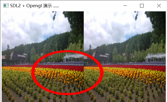
Of course, the circle is a little flat, which is the length width ratio of the interface. It is not difficult to solve. The length width ratio of the picture is 1.6
The UV coordinate is x, y, and the distance is pow (pow (x - 0.4,2) * 1.6 + pow ((x - 0.6), 2), 0.5);
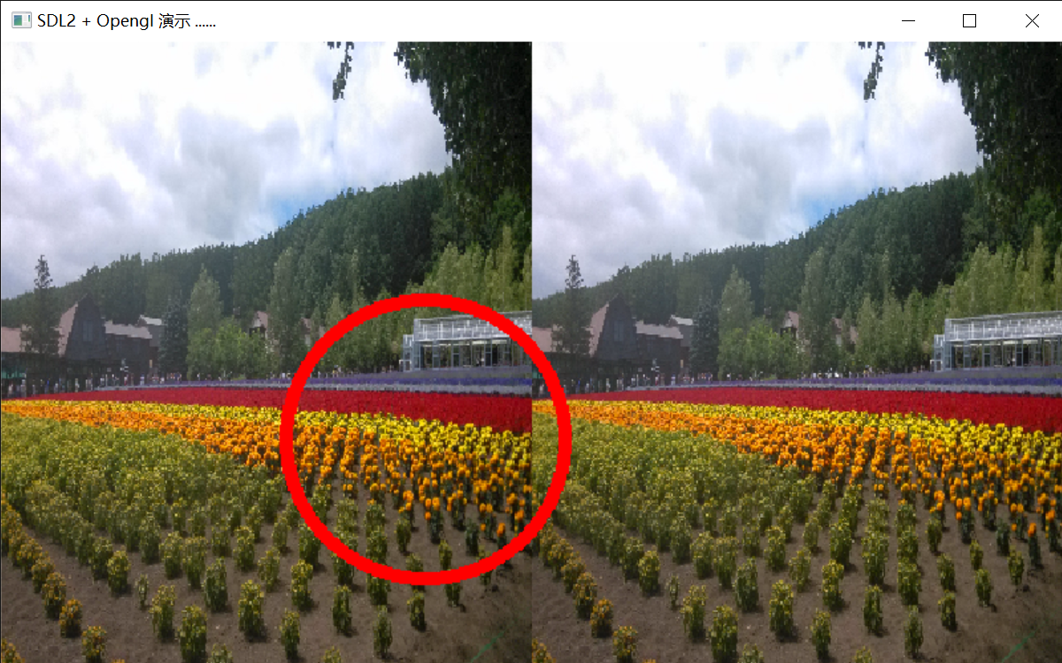
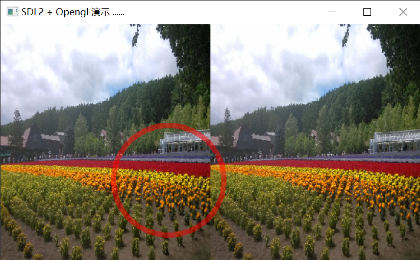
Of course, the red circle can also be made translucent
    float len = pow( pow((sTexCoord.x-0.4)*1.6 ,2 ) + pow(sTexCoord.y-0.6,2),0.5);\n\
    if(len <= 0.22 && len >=0.2)\n\
        outColor = outColor * 0.5 + vec4(1.0,0.0,0.0,1.0)* 0.5;\n\
There are many ways to make pictures transparent,
One is to use two textures to sample and mix in the slice shader. This method has certain limitations. In addition to global mixing, the implementation of local mixing is very troublesome, because regardless of the size of the texture, the OpenGL shader needs to normalize the texture coordinates during processing. For example, the method of sampling calculation can also realize the transparency of local mixing, but parameters must be input, Inputting data into GLSL is a very troublesome thing, and the calculation of sampling points is also troublesome. Although the length of GLSL shader program is almost unlimited, the preparation and debugging of shader is much more difficult than that of c + +, especially the lack of single-step debugging and troubleshooting means, and the keyword completion and inspection are not convenient as other programming languages, The intermediate result check must also be realized by using CPU simulation with the help of special tools, and the universality of such tools is very poor. In terms of compilation efficiency alone, what can be realized from the outside should still be realized from the outside.
The second is external implementation. The implementation method is also very simple. First generate the background in the frame cache, that is, render the background picture first, and then render the foreground picture. To make the foreground picture transparent, two conditions must be met: one is to turn on the Alpha transparency of OpenGL, and the other is to set the Alpha channel value of the foreground. If the format of the foreground image itself is RGBA or other color format containing Alpha channel and has been set, it can be used directly. Otherwise, it needs to be set in the slice shader. The method is simple,
//Turn on Alpha blending of OpenGL
    glEnable(GL_BLEND);
    glBlendFunc(GL_SRC_ALPHA, GL_ONE_MINUS_SRC_ALPHA);//Set fusion function

//Rendering, fan Quad, four vertices from the first vertex
    glDrawArrays(GL_TRIANGLE_FAN, 0, 4);

//Turn off mixing
    glDisable(GL_BLEND);

//Set the Alpha transparency of the output color in the slice shader, and the value is (0.0 -- 1.0)
outColor.a = Alpha;\n\
Vertex shader is different from the task of slice shader. If the main task of slice shader is to calculate the color through sampling, the focus of vertex shader is to calculate the position. The position includes various topological deformations such as size, movement and rotation. Vertex shader can usually receive vertex color, illumination, etc., so as to affect the final rendering result, However, I haven't studied this part thoroughly, and the common SDL application involves less in this aspect. I won't introduce it here. The focus is on the transformation and calculation of position. The transformation of graphics is inseparable from matrix operation. The use of matrix can greatly reduce the burden of programming. Common transformations can often be done with one matrix. The following are introduced respectively
Identity matrix. Identity matrix is a matrix whose diagonal is 1 and other cells are 0. In operation, the identity matrix of the same dimension is multiplied by the array of the same dimension, and the result remains unchanged. GLSL uses a 4-dimensional array to describe the position, {x,y,z,w} x, y and z represent the position of X, y and z axes respectively, and W represents the distance of the observer. In GLSL shader, vec2, vec3 and vec4 are used to represent 2-dimensional, 3-dimensional and 4-dimensional arrays respectively, and mat2, mat3 and mat4 are used to represent 2-ary, 3-ary and 4-ary matrices. Mat2 (1), mat3 (1) and mat4 (1) represent the corresponding identity matrix respectively. vec4 x = mat4(1) * x. The geometric meaning of each position of the matrix is difficult to understand, but it is enough to remember a few special positions.
4-dimensional matrix 1 # diagonal

x. Represents the width of the x-axis, Y represents the width of the y-axis, Z represents the width of the z-axis, and W represents the observer. For 2D graphics, if x increases and the width increases, y will cause a change in height. Z does not work. If w increases, the graphics will become farther, the rectangle will become smaller, and vice versa.
4-dimensional matrix 2-displacement matrix

For 2D application, x represents x-axis movement, y represents y-axis movement, z does not work, and w has the same effect as above
4-dimensional matrix observer position matrix

x. y and z respectively represent the position of the observer, which moves along the corresponding axis, and the effect of w remains unchanged
There is also rotation matrix. I won't be verbose here. There are a lot of introductions on the Internet, which are better than me. Here we mainly talk about the usage of matrix, or using self built structure SDL_fColor, mainly because this structure is exactly the same size as the four-dimensional array in GLSL, and the external reference {r,g,b,a} is the same as vec4 in GLSL,
In order to control the size of picture display, SDL is introduced_ fColor g_ zoom = {x,y,z,w}; Where x and y control the left and right and up and down displacement respectively, Z has no effect, and W controls the amplification and reduction.
In order to control the image rotation, SDL is introduced_ fColor g_ roll = {x,y,z,w}; Where x, y and Z respectively control the rotation angle of X, y and Z axes. W controls zoom in and zoom out
Modify the vertex shader code to
//Vertex Shader
const static GLchar* const vertexShader =
"#version 130\n\
in vec2 position;\n\
in vec2 TexCoord;\n\
uniform vec4 v_data[20];\n\
out vec2 sTexCoord;\n\
void main()\n\
{\n\
    vec4 zoom  = v_data[4];\n\
    vec4 roll  = v_data[5];\n\
    gl_Position = vec4(position, 0.0, 1.0) ;\n\
    if(zoom.w > 0.0)//Move zoom \ n\
    {\n\
        mat4 m_zoom = mat4(1.0);\n\
        m_zoom[3] = zoom;\n\
        gl_Position = m_zoom * gl_Position;\n\
    }\n\
    if(roll.w >1.0)//Rotate \ n\
    {\n\
        float s,c;\n\
        mat4 m_roll = mat4(1.0);//X axis \ n\
        m_roll[3][3] = roll.w;\n\
        m_roll[1][1] = m_roll[2][2] = cos(roll.x);\n\
        m_roll[1][2] = sin(roll.x);\n\
        m_roll[2][1] = -sin(roll.x);\n\
        gl_Position = m_roll * gl_Position;\n\
        m_roll = mat4(1.0);//Y axis \ n\
        m_roll[0][0] = m_roll[2][2] = cos(roll.y);\n\
        m_roll[0][2] = sin(roll.y);\n\
        m_roll[2][0] = -sin(roll.y);\n\
        gl_Position = m_roll * gl_Position;\n\
        m_roll = mat4(1.0);//Z axis \ n\
        m_roll[0][0] = m_roll[1][1] = cos(roll.z);\n\
        m_roll[0][1] = sin(roll.z);\n\
        m_roll[1][0] = -sin(roll.z);\n\
        gl_Position = m_roll * gl_Position;\n\
    }\n\
    sTexCoord = TexCoord ;\n\
}";
Where v_data[20] shares a set of parameters with the slice shader
Finally, paste a group of effect pictures
