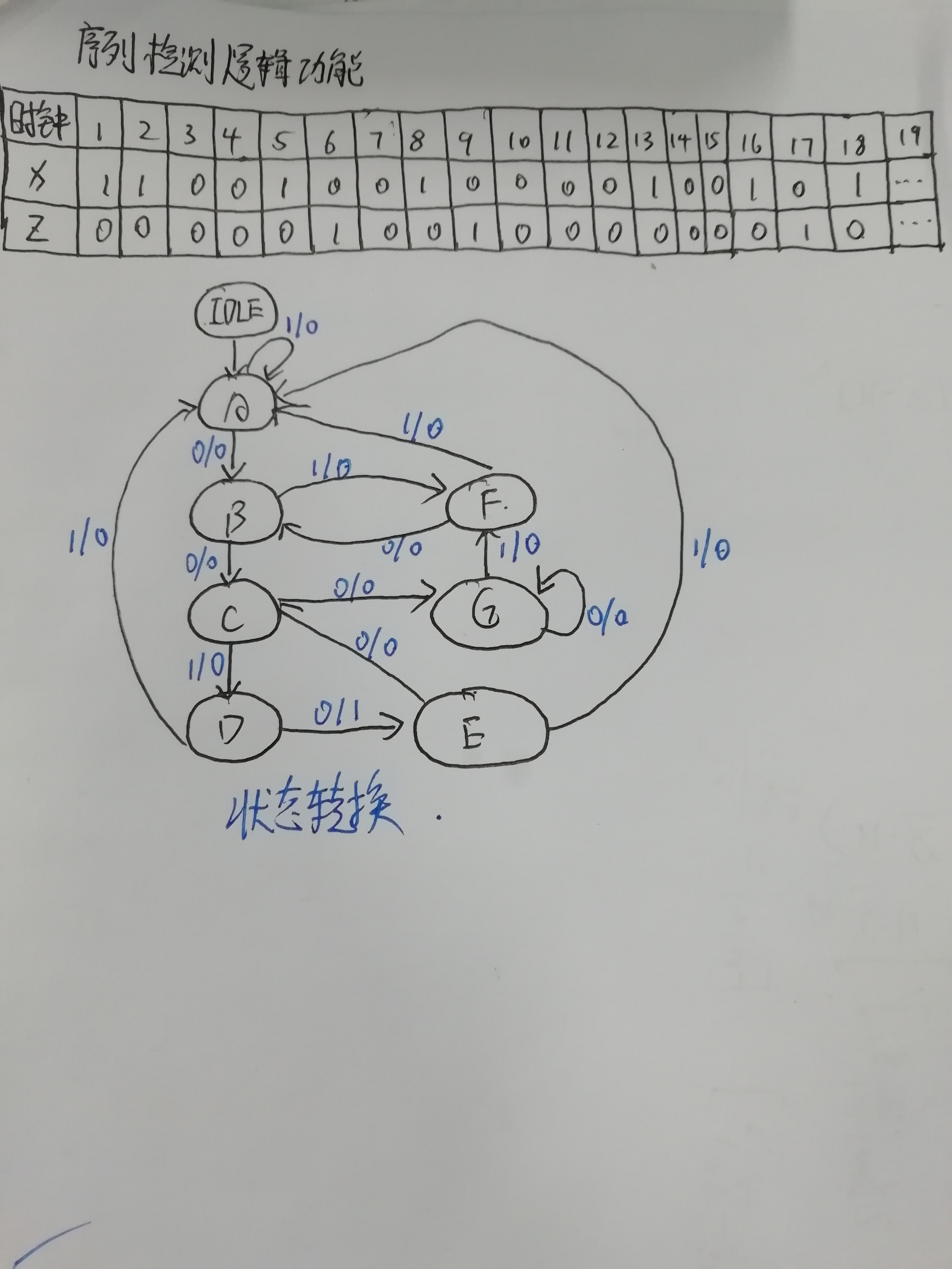
IDLE is the initial state, A represents the first state "1", B represents the second state "10",C represents the third state "100",D represents the fourth state "1001",E represents the state to be output "10010", G and F represent the redundant states "1000" and "10001", respectively.
module cy4( clk,rst_b,In,Y);
input clk,rst_b,In;
output Y;
reg[2:0]current_state,next_state;
wire Y;
parameter IDLE = 3'd0,//Each decimal number represents a different state
             A = 3'd1,
			 B = 3'd2,
			 C = 3'd3,
			 D = 3'd4,
			 E = 3'd5,//Status with output 1
			 F = 3'd6,
			 G = 3'd7;
assign Y = (next_state == D && In == 0)?1:0;
//When the status is D, another 0 is received, indicating that the output Y of 10010 is high
always @(posedge clk or negedge rst_b)
if(!rst_b) current_state <= IDLE;
else current_state <= next_state;

always @(In,current_state)
case(current_state)
IDLE: if(In == 1) next_state <= A;
      else next_state <= IDLE;
A: if(In == 0) next_state <= B;
   else next_state <= A;
B: if(In == 0) next_state <= C;
   else next_state <= F;
C: if(In == 1) next_state <= D;
   else next_state <= G;
D: if(In == 0) next_state <= E;
   else next_state <= A;
E: if(In == 0) next_state <= C;
   else next_state <= A;
F: if(In == 0) next_state <= B;
   else next_state <= A;
G: if(In == 0) next_state <= G;
   else next_state <= F;
default:next_state <= IDLE;
endcase
endmodule
Test script code:
`timescale 1 ns/ 1 ps
`define halfperiod 20
module cy4_vlg_tst();
reg clk;
reg rst_b;
reg[23:0]data;
wire Y,In;
assign In = data[23];

cy4 i1 (

	.In(In),
	.Y(Y),
	.clk(clk),
	.rst_b(rst_b)
);
initial
begin
 clk=0;
 rst_b=1;
 #2 rst_b=0;
 #30 rst_b=1; / / reset signal
 data=20'b1100_1001_0000_1001_0100;//Stream data
 #(` halfperiod*1000)$stop; / / stop the simulation after 500 clock cycles
end
always #(` halfperiod)clk = ~clk; / / clockticks
always @(posedge clk)
       #2 data={data[22:0],data[23]}; / / shift output bitstream
cy4 m(.In(In),.Y(Y),.clk(clk),.rst_b(rst_b));
//Call sequence detector module
endmodule
timing simulation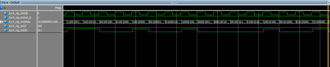
President's design ideas:
1. List the logic functions of the detector
2. Draw the state diagram and pay attention to the redundant state diagram.
3. Design code
4. Write test code
5. Timing simulation