Catalog
Setting up environment learning VLAN with GNS3
Recently, learning the classic "TCP/IP Details", this part of VLAN (Virtual Local Area Network) does not read very well. After this GNS3 simulation experiment, the understanding of VLAN has been deepened and this process is recorded.
One.GNS3 Installation and Configuration
GNS3 is a network virtual software with graphical interface that can run on multiple platforms including Windows, Linux, and MacOS. Reference for installation and configuration of GNS3 here , which is full of illustrations and detailed instructions.
Two.Build GNS3 Analog Topology
Following the above tutorial, once the installation is complete, let's first configure the default router settings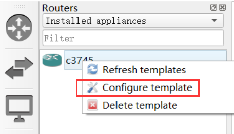
Select Configure template, you must add a memory card here. Without setting the VLAN data on it, it cannot be saved and error will occur.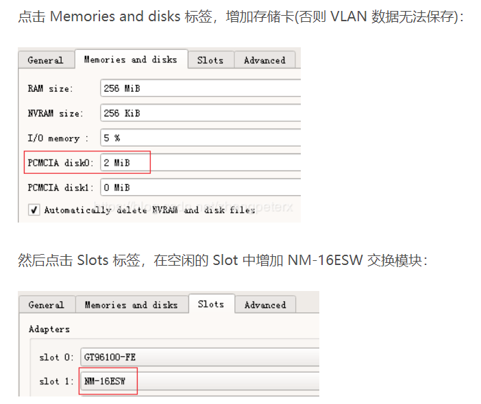
The experimental topology is shown below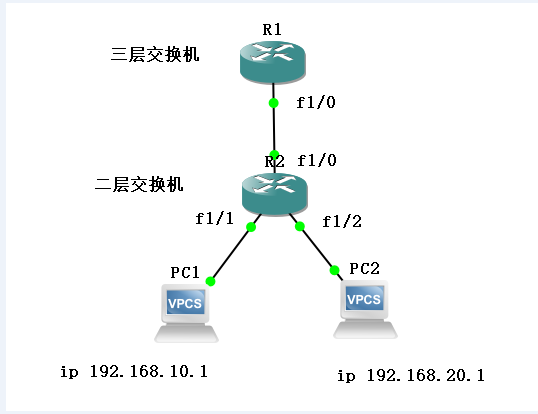
Here, routers are used to simulate Layer 2 and Layer 3 switches, and VPCS is used to simulate PCs.Because 16 switch modules have been added, the port to which the switch connects should be the port starting with f1, not the port of f0.
Three.Experimental process
Set IP information for PC1 and PC2
PC1> ip 192.168.10.1 255.255.255.0 192.168.10.254
    Checking for duplicate address...
PC1 : 192.168.10.1 255.255.255.0 gateway 192.168.10.254
PC2> ip 192.168.20.1 255.255.255.0 192.168.20.254
  Checking for duplicate address...
PC2 : 192.168.20.1 255.255.255.0 gateway 192.168.20.254
It is not possible for PC1 to ping PC2 at this time because the corresponding routing information is not configured
PC1> ping 192.168.20.1
  host (192.168.10.254) not reachable
Starting with the VLAN setup, here is a concept:
VTP (VLAN Trunking Protocol): is a VLAN relay protocol, also known as a virtual local area network trunk protocol.It is a Cisco Private Agreement.The purpose is that more than a dozen switches in an enterprise network can configure VLANs with a heavy workload. You can use the VTP protocol to configure one switch as a VTP Server and the rest as a VTP Client so that they can learn VLAN information on the server automatically.(Baidu Encyclopedia)
Here we configure VLAN information on a three-tier router, while a two-tier router acts as a VTP Client to learn VLAN information on a three-tier router.
Layer 3 Switch Configuration
Open trunk, configure VLAN; configure IP address for VLAN
R1#en
R1#conf t
R1(config)#int f1/0
R1(config-if)#swit trunk enca dot1q
R1(config-if)#swit mode trunk
R1(config-if)#end
R1#vlan data
R1(vlan)#vtp doamin hello
R1(vlan)#vtp pass 123
R1(vlan)#vtp server
R1(vlan)#vlan 10
R1(vlan)#vlan 20
R1(vlan)#exit
R1(config)#int vlan 10
R1(config-if)#ip add 192.168.10.254 255.255.255.0
R1(config-if)#int vlan 20
R1(config-if)#ip add 192.168.20.254 255.255.255.0
Layer 2 Switch Configuration
Upper interface opens trunk to get VLAN configuration information
R2#conf t
R2(config)#int f1/0
R2(config-if)#swit trunk enca dot1q
R2(config-if)#swit mode trunk
R2(config-if)#end
R2#vlan data
R2(vlan)#vtp domain hello
R2(vlan)#vtp pass 123
R2(vlan)#vtp cli
R2(vlan)#exit
R2#conf t
R2(config)#int f1/1
R2(config-if)#swit mode acce
R2(config-if)#swit acce vlan 10
R2(config-if)#int f1/2
R2(config-if)#swit mode acce
R2(config-if)#swit acce vlan 20
R2(config-if)#end
The above commands are from Cisco routers and switches, unfamiliar to see [here]
The possible errors here are: Failure to save vlan information, because the emulator needs to write flash, and if there is pre-stored information in it, write failure is likely due to insufficient capacity
% not enough space on flash to store vlan database. trying squeeze...
% error squeezing flash - (Operation not supported on this file)
Error on database apply 40: NV storage failure
Use 'abort' command to exit
You can type abort, empty flash, and then write
R2(vlan)#abort
Aborting....
R2#ena
R2#erase flash:
Erasing the flash filesystem will remove all files! Continue? [confirm]y
Current DOS File System flash card in flash: will be formatted into Low End File System flash card!  Continue? [confirm]y
Erasing device... eeeeeeeeeeeeeeeeeeeeeeeeeeeeeeeeeeeeeeeeeeeeeeeeeeeeeeeeeeeeeeeeeeeeeeeeeeeeeeeeeeeeeeeeee ...erased
Erase of flash: complete
R2#vlan data
R2(vlan)#vlan 10
VLAN 10 added:
    Name: VLAN0010
R2(vlan)#vlan 20
VLAN 20 added:
    Name: VLAN0020
R2(vlan)#exit
APPLY completed.
Exiting....
After setup is complete
PC1> ping 192.168.20.1
192.168.20.1 icmp_seq=1 timeout
192.168.20.1 icmp_seq=2 timeout
84 bytes from 192.168.20.1 icmp_seq=3 ttl=63 time=19.546 ms
84 bytes from 192.168.20.1 icmp_seq=4 ttl=63 time=10.756 ms
84 bytes from 192.168.20.1 icmp_seq=5 ttl=63 time=13.912 ms
At this point, the two VLAN s can now ping properly
You can already see the VLAN number in the message by WireShark grabbing packets between switches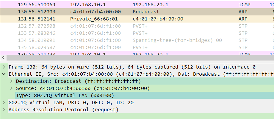
Four.summary
In this experiment, we set up the interaction between VTP server and VTP client about VLAN information, and saw the application of VLAN in subnet partitioning.
The advantages of VLAN s are:
(1) Separation of ports.Ports in different VLAN s cannot communicate even on the same switch.Such a physical switch can be used as multiple logical switches.
(2) Network security.Different VLAN s cannot communicate directly, eliminating the broadcast storm.
(3) Flexible management.Changing the network a user belongs to does not require changing ports and connections, just changing the software configuration.Together with VTP technology, it is easy to configure a large number of switches.
The understanding of VLAN technology has been unclear while reading, and only after experimentation was done, a new understanding of VLAN technology suddenly emerged.
Reference material: https://blog.csdn.net/azhe_1202/article/details/83343765