catalogue
2. MySQL master-slave replication
3. Sharding JDBC implementation of read-write separation
4. MySQL sub database and table principle
5. Sharding JDBC implements sub database and sub table
1. Overview
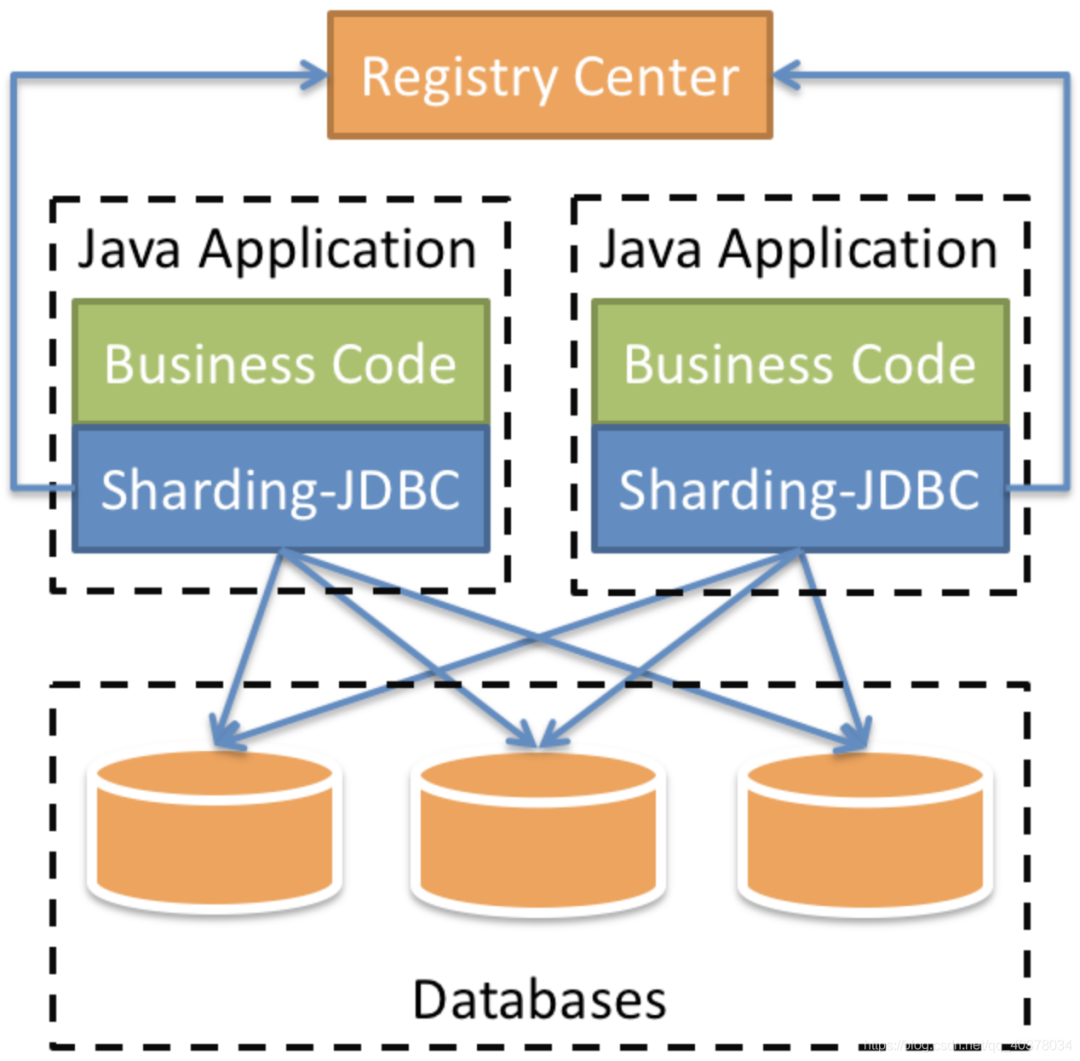
Shardingsphere Jdbc is positioned as a lightweight Java framework and provides additional services in the Jdbc layer of Java. It uses the client to connect directly to the database and provides services in the form of jar package. It can be understood as an enhanced version of Jdbc driver, which is fully compatible with Jdbc and various ORM frameworks
2. MySQL master-slave replication
1) . configure mysql master-slave replication with docker
1) Create the directory required by the master server
mkdir -p /usr/local/mysqlData/master/cnf
mkdir -p /usr/local/mysqlData/master/data
2) Define master server profile
vim /usr/local/mysqlData/master/cnf/mysql.cnf
[mysqld]
## Set up server_id, be unique
server-id=1
## Enable binlog
log-bin=mysql-bin
## binlog cache
binlog_cache_size=1M
## binlog format (mixed, statement, row, default format is statement)
binlog_format=mixed
3) Create and start mysql main service
docker run -itd -p 3306:3306 --name master -v /usr/local/mysqlData/master/cnf:/etc/mysql/conf.d -v /usr/local/mysqlData/master/data:/var/lib/mysql -e MYSQL_ROOT_PASSWORD=123456 mysql:5.7
4) Add a user reader that replicates master data for use from the server
[root@aliyun /]# docker ps
CONTAINER ID        IMAGE               COMMAND                  CREATED             STATUS              PORTS                               NAMES
6af1df686fff        mysql:5.7           "docker-entrypoint..."   5 seconds ago       Up 4 seconds        0.0.0.0:3306->3306/tcp, 33060/tcp   master
[root@aliyun /]# docker exec -it master /bin/bash
root@41d795785db1:/# mysql -u root -p123456

mysql> GRANT REPLICATION SLAVE ON *.* to 'reader'@'%' identified by 'reader';
Query OK, 0 rows affected, 1 warning (0.00 sec)

mysql> FLUSH PRIVILEGES;
Query OK, 0 rows affected (0.00 sec)
5) Create the required directory from the server and edit the configuration file
mkdir /usr/local/mysqlData/slave/cnf -p
mkdir /usr/local/mysqlData/slave/cnf -p
vim /usr/local/mysqlData/slave/cnf/mysql.cnf
[mysqld]
## Set up server_id, be unique
server-id=2
## Enable binlog for use when Slave is the Master of other Slave
log-bin=mysql-slave-bin
## relay_log configure relay log
relay_log=edu-mysql-relay-bin
## If you need to synchronize functions or stored procedures
log_bin_trust_function_creators=true
## binlog cache
binlog_cache_size=1M
## binlog format (mixed, statement, row, default format is statement)
binlog_format=mixed
## Skip all errors encountered in master-slave replication or specified types of errors to avoid the interruption of slave side replication
## For example, the 1062 error refers to the duplication of some primary keys, and the 1032 error is due to the inconsistency between the primary and secondary database data
slave_skip_errors=1062
6) Create and run mysql slave server
docker run -itd -p 3307:3306 --name slaver -v /usr/local/mysqlData/slave/cnf:/etc/mysql/conf.d -v /usr/local/mysqlData/slave/data:/var/lib/mysql -e MYSQL_ROOT_PASSWORD=123456 mysql:5.7
7) Configure the information to connect to the master server on the slave server
First, view the master on the master server_ log_ file,master_log_pos two parameters, and then switch to the slave server to set the connection information of the master server
Execute on main service:
root@6af1df686fff:/# mysql -u root -p123456

mysql> show master status;
+------------------+----------+--------------+------------------+-------------------+
| File             | Position | Binlog_Do_DB | Binlog_Ignore_DB | Executed_Gtid_Set |
+------------------+----------+--------------+------------------+-------------------+
| mysql-bin.000003 |      591 |              |                  |                   |
+------------------+----------+--------------+------------------+-------------------+
1 row in set (0.00 sec)
docker views the ip address of the primary server container
[root@aliyun /]# docker inspect --format='{{.NetworkSettings.IPAddress}}' master
172.17.0.2
From the server:
[root@aliyun /]# docker exec -it slaver /bin/bash
root@fe8b6fc2f1ca:/# mysql -u root -p123456

mysql> change master to master_host='172.17.0.2',master_user='reader',master_password='reader',master_log_file='mysql-bin.000003',master_log_pos=591;
8) Start the I/O thread and SQL thread from the server
mysql> start slave;
Query OK, 0 rows affected, 1 warning (0.00 sec)

mysql> show slave status\G
*************************** 1. row ***************************
               Slave_IO_State: Waiting for master to send event
                  Master_Host: 172.17.0.2
                  Master_User: reader
                  Master_Port: 3306
                Connect_Retry: 60
              Master_Log_File: mysql-bin.000003
          Read_Master_Log_Pos: 591
               Relay_Log_File: edu-mysql-relay-bin.000002
                Relay_Log_Pos: 320
        Relay_Master_Log_File: mysql-bin.000003
             Slave_IO_Running: Yes
            Slave_SQL_Running: Yes
Slave_IO_Running: Yes,Slave_SQL_Running: Yes indicates successful startup
2) , binlog and redo log review
1) redo log
InnoDB first puts the redo log into the redo log buffer, and then refreshes it to the redo log file at a certain frequency
The redo log buffer will be refreshed to the redo log file in the following three cases:
-
The Master Thread flushes the redo log buffer to the redo log file every second
-
When each transaction is committed, the redo log buffer will be refreshed to the redo log file
-
When the remaining space of the redo log buffer pool is less than 1 / 2, the redo log buffer will be flushed to the redo log file
The full name of the WAL technology often used in MySQL is Write Ahead Log, that is, when a transaction is committed, write the redo log first and then modify the page. That is, when a record needs to be updated, InnoDB will first write the record to the redo log and update the page of Buffer Pool. At this time, the update operation is completed
Buffer Pool is the cache of physical pages. Any modification to InnoDB will be performed on the page of Buffer Pool first, and then such pages will be marked as dirty pages and placed on a special Flush List. Later, these pages will be written to the disk periodically by a special dirty brushing thread
InnoDB's redo log is a fixed size. For example, it can be configured as a group of four files, each of which is 1GB in size. It is used circularly. It is written from the beginning, and then back to the beginning after writing to the end. It is written in sequence, which saves the IO consumption of random writing to the disk
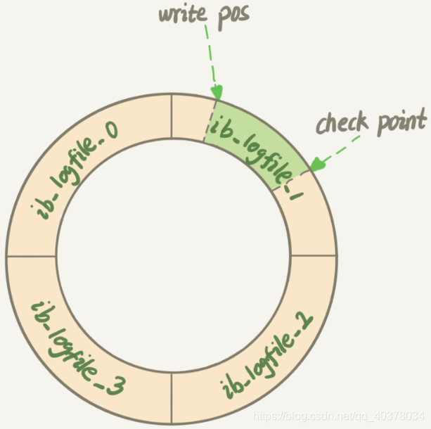
Write Pos is the position of the current record. It moves back while writing. After writing to the end of file No. 3, it returns to the beginning of file No. 0. Check Point is the current position to be erased, which is also moved back and cycled. Before erasing the record, the record should be updated to the data file
The empty part between Write Pos and Check Point can be used to record new operations. If Write Pos catches up with Check Point, no new updates can be performed at this time. You need to stop and erase some records to push Check Point forward
When the database goes down, the database does not need to redo all logs, because the pages before Check Point have been flushed back to disk. Only the redo log after Check Point needs to be recovered, which shortens the recovery time
When the buffer pool is not enough, the least recently used page will overflow according to the LRU algorithm. If this page is a dirty page, you need to forcibly execute Check Point to refresh the dirty page back to disk
2) binlog (archive log)
MySQL as a whole has two parts: one is the Server layer, which mainly does things at the functional level of MySQL; Another is the engine layer, which is responsible for specific matters related to storage. redo log is a unique log of InnoDB engine, and the Server layer also has its own log, called binlog
binlog records all operations that change the MySQL database, excluding such operations as SELECT and SHOW. It is mainly used for master-slave replication of the database and incremental recovery of data
When using mysqldump for backup, only the data for a period of time is fully backed up. However, if the database server fails suddenly after backup, the binlog log will be used at this time
There are three binlog formats: state, ROW and MIXED
-
STATEMENT mode: the original SQL STATEMENT is recorded in binlog. The advantage is that there is no need to record the data changes of each row, which reduces the amount of binlog logs, saves IO and improves performance. The disadvantage is that in some cases, the data in the master slave will be inconsistent
-
ROW mode: do not record the context information of each SQL STATEMENT, just record which data has been modified and what it has been modified. This solves the inconsistency of data in master slave in the state mode. The disadvantage is that a large number of logs will be generated, especially when the alter table is used, the logs will soar
-
MIXED mode: the above two modes are used in combination. For general replication, binlog is saved in the state mode. For operations that cannot be replicated in the state mode, binlog is saved in the ROW mode. MySQL will select the log saving method according to the executed SQL statements
3) The difference between redo log and binlog log
-
redo log is unique to InnoDB engine; binlog is implemented in the Server layer of MySQL and can be used by all engines
-
redo log is a physical log that records the changes made to a certain data; binlog is a logic log that records the original logic of the statement. For example, add 1 to the c field of the line ID=2
-
redo log is written circularly, and the space is fixed and will be used up; Binlog can be written additionally. After the binlog file is written to a certain size, it will switch to the next one and will not overwrite the previous log
4) Two stage submission
create table T(ID int primary key, c int);
update T set c=c+1 where ID=2;
The internal process of the executor and InnoDB engine when executing this update statement:
-
The actuator first finds the engine and takes the line ID=2. ID is the primary key, and the engine finds this row directly by tree search. If the data of the line ID=2 is already in memory, it will be directly returned to the actuator; Otherwise, you need to read memory from disk before returning
-
The actuator obtains the row data given by the engine, adds 1 to the value, obtains a new row of data, and then calls the engine interface to write the new row of data
-
The engine updates this line of new data into memory and records the update operation in the redo log. At this time, the redo log is in the prepare state. The executor is then informed that execution is complete and the transaction can be committed at any time
-
The actuator generates the binlog of this operation and writes the binlog to disk
-
The executor calls the commit transaction interface of the engine. The engine changes the redo log just written to the commit status and the update is completed
The execution flow chart of the update statement is as follows. In the figure, the light box indicates that it is executed inside InnoDB, and the dark box indicates that it is executed in the actuator
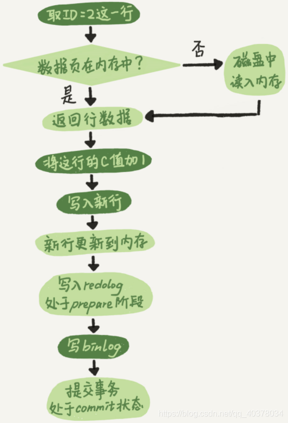
The redo log writing is divided into two steps: prepare and commit, which are two-phase commit
3) Principle of MySQL master-slave replication
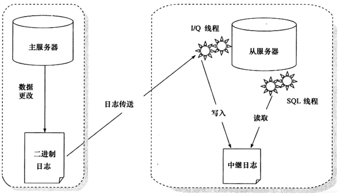
A long connection is maintained between slave Library B and master library a. There is a thread inside main library a, which is dedicated to serving the long connection from library B. The complete process of a transaction log synchronization is as follows:
-
On slave database B, set the IP, port, user name and password of master database A through the change master command, and where to start requesting binlog. This location contains the file name and log offset
-
Execute the start slave command on slave library B. at this time, the slave library will start two threads, I/O thread and SQL thread in the figure. The I/O thread is responsible for establishing a connection with the main library
-
After verifying the user name and password, main database A starts to read binlog locally according to the location transmitted from database B and send it to database B
-
After getting the binlog from library B, it is written to the local file, which is called the relay log
-
The SQL thread reads the relay log, parses the commands in the log, and executes them
Due to the introduction of multi-threaded replication scheme, SQL thread has evolved into multiple threads
Master-slave replication is not synchronous in full real time, but asynchronous in real time. There is an execution delay between the master and slave services. If the pressure on the master server is great, it may lead to a large delay between the master and slave servers
3. Sharding JDBC implementation of read-write separation
1) Create a new Springboot project and introduce related dependencies
<dependencies>
    <dependency>
        <groupId>org.springframework.boot</groupId>
        <artifactId>spring-boot-starter-web</artifactId>
    </dependency>
    <dependency>
        <groupId>org.mybatis.spring.boot</groupId>
        <artifactId>mybatis-spring-boot-starter</artifactId>
        <version>2.1.4</version>
    </dependency>
    <dependency>
        <groupId>mysql</groupId>
        <artifactId>mysql-connector-java</artifactId>
        <scope>runtime</scope>
    </dependency>
    <dependency>
        <groupId>com.alibaba</groupId>
        <artifactId>druid-spring-boot-starter</artifactId>
        <version>1.1.21</version>
    </dependency>
    <dependency>
        <groupId>org.apache.shardingsphere</groupId>
        <artifactId>sharding-jdbc-spring-boot-starter</artifactId>
        <version>4.0.0-RC1</version>
    </dependency>
    <dependency>
        <groupId>org.projectlombok</groupId>
        <artifactId>lombok</artifactId>
        <optional>true</optional>
    </dependency>
    <dependency>
        <groupId>org.springframework.boot</groupId>
        <artifactId>spring-boot-starter-test</artifactId>
        <scope>test</scope>
    </dependency>
</dependencies>
2),application.properties configuration file
spring.main.allow-bean-definition-overriding=true
#Show sql
spring.shardingsphere.props.sql.show=true

#Configure data sources
spring.shardingsphere.datasource.names=ds1,ds2,ds3

#master-ds1 database connection information
spring.shardingsphere.datasource.ds1.type=com.alibaba.druid.pool.DruidDataSource
spring.shardingsphere.datasource.ds1.driver-class-name=com.mysql.cj.jdbc.Driver
spring.shardingsphere.datasource.ds1.url=jdbc:mysql://47.101.58.187:3306/sharding-jdbc-db?useUnicode=true&useSSL=false&serverTimezone=Asia/Shanghai
spring.shardingsphere.datasource.ds1.username=root
spring.shardingsphere.datasource.ds1.password=123456
spring.shardingsphere.datasource.ds1.maxPoolSize=100
spring.shardingsphere.datasource.ds1.minPoolSize=5

#slave-ds2 database connection information
spring.shardingsphere.datasource.ds2.type=com.alibaba.druid.pool.DruidDataSource
spring.shardingsphere.datasource.ds2.driver-class-name=com.mysql.cj.jdbc.Driver
spring.shardingsphere.datasource.ds2.url=jdbc:mysql://47.101.58.187:3307/sharding-jdbc-db?useUnicode=true&useSSL=false&serverTimezone=Asia/Shanghai
spring.shardingsphere.datasource.ds2.username=root
spring.shardingsphere.datasource.ds2.password=123456
spring.shardingsphere.datasource.ds2.maxPoolSize=100
spring.shardingsphere.datasource.ds2.minPoolSize=5

#slave-ds3 database connection information
spring.shardingsphere.datasource.ds3.type=com.alibaba.druid.pool.DruidDataSource
spring.shardingsphere.datasource.ds3.driver-class-name=com.mysql.cj.jdbc.Driver
spring.shardingsphere.datasource.ds3.url=jdbc:mysql://47.101.58.187:3307/sharding-jdbc-db?useUnicode=true&useSSL=false&serverTimezone=Asia/Shanghai
spring.shardingsphere.datasource.ds3.username=root
spring.shardingsphere.datasource.ds3.password=123456
spring.shardingsphere.datasource.ds.maxPoolSize=100
spring.shardingsphere.datasource.ds3.minPoolSize=5

#Configure the default data source ds1 default data source, which is mainly used for writing
spring.shardingsphere.sharding.default-data-source-name=ds1
#Configure master-slave name
spring.shardingsphere.masterslave.name=ms
#Set the master database to be responsible for writing data
spring.shardingsphere.masterslave.master-data-source-name=ds1
#Configuring slave slave nodes
spring.shardingsphere.masterslave.slave-data-source-names=ds2,ds3
#Configure the load balancing strategy of the slave node and adopt the polling mechanism
spring.shardingsphere.masterslave.load-balance-algorithm-type=round_robin

#Integrate the configuration of mybatis
mybatis.type-aliases-package=com.ppdai.shardingjdbc.entity
3) , create t_user table
CREATE TABLE `t_user` (
  `id` int(11) NOT NULL AUTO_INCREMENT,
  `nickname` varchar(100) DEFAULT NULL,
  `password` varchar(100) DEFAULT NULL,
  `sex` int(11) DEFAULT NULL,
  `birthday` varchar(50) DEFAULT NULL,
  PRIMARY KEY (`id`)
) ENGINE=InnoDB AUTO_INCREMENT=4 DEFAULT CHARSET=utf8mb4;
4) , define Controller, Mapper, Entity
@Data
public class User {
    private Integer id;

    private String nickname;

    private String password;

    private Integer sex;

    private String birthday;
}
@RestController
@RequestMapping("/api/user")
public class UserController {
@Autowired
private UserMapper userMapper;
@PostMapping("/save")
public String addUser() {
User user = new User();
user.setNickname("zhangsan" + new Random().nextInt());
user.setPassword("123456");
user.setSex(1);
user.setBirthday("1997-12-03");
userMapper.addUser(user);
return "success";
}
@GetMapping("/findUsers")
public List<User> findUsers() {
return userMapper.findUsers();
}
}public interface UserMapper {
@Insert("insert into t_user(nickname,password,sex,birthday) values(#{nickname},#{password},#{sex},#{birthday})")
void addUser(User user);
@Select("select * from t_user")
List<User> findUsers();
}5) . verification
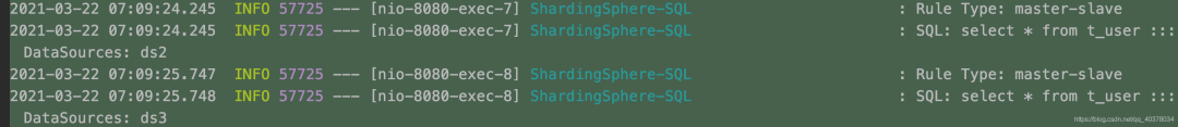
Three data sources in the startup log were initialized successfully:

call http://localhost:8080/api/user/save Go all the way to the ds1 master node

call http://localhost:8080/api/user/findUsers Go all the way to the ds2 and ds3 nodes, and enter by polling
4. MySQL sub database and table principle
1) . sub warehouse and sub table
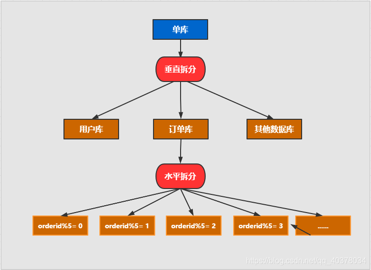
Horizontal split: split the data of the same table into different libraries and different tables. It can be split according to time, region or a business key dimension, or through hash, and finally access specific data through routing. The structure of each table after splitting is consistent
Vertical splitting: splitting a table with many fields into multiple tables or libraries. The structure of each library table is different, and each library table contains some fields. Generally speaking, it can be split according to business dimensions. For example, the order table can be split into order, order support, order address, order goods, order extension and other tables; You can also split the data according to the degree of cold and hot. 20% of the hot fields are split into one table and 80% of the cold fields are split into another table
2) . non stop database and table data migration
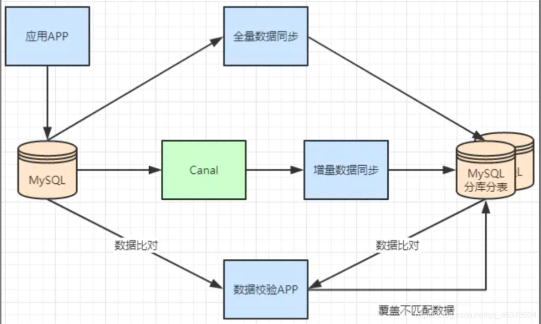
Generally, there is a process to split a database. At first, it is a single table, and then it is slowly split into multiple tables. Let's look at how to smoothly transition from MySQL single table to MySQL sub database and sub table architecture
-
MySQL+Canal is used for incremental data synchronization, and the database and table middleware is used to route the data to the corresponding new table
-
Using the database and table middleware, the full amount of data is imported into the corresponding new table
-
Through the comparison of single table data and sub database and sub table data, the mismatched data is updated to the new table
-
After the data is stable, switch the single table configuration to the sub database and sub table configuration
5. Sharding JDBC implements sub database and sub table
1) Logic table
User data is split into two tables according to order id%2: t_order0 and t_order1. Their logical table name is: t_order
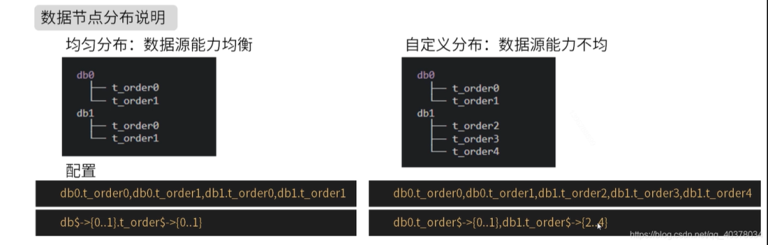
Same table for multiple data sources:
#Multiple data sources $- > {0.. n} Logical table name $- > {0.. n} same table
spring.shardingsphere.sharding.tables.t_order.actual-data-nodes=ds$->{0..1}.t_order$->{0..1}
Different tables from multiple data sources:
#Multiple data sources $- > {0.. n} Logical table name $- > {0.. n} is different
spring.shardingsphere.sharding.tables.t_order.actual-data-nodes=ds0.t_order$->{0..1},ds1.t_order$->{2..4}
Single warehouse sub table:
#Configuration mode of single data source
spring.shardingsphere.sharding.tables.t_order.actual-data-nodes=ds0.t_order$->{0..4}
Specify all manually:
spring.shardingsphere.sharding.tables.t_order.actual-data-nodes=ds0.t_order0,ds1.t_order0,ds0.t_order1,ds1.t_order1
2) . inline slicing strategy
spring.shardingsphere.sharding.tables.t_order.actual-data-nodes=ds$->{0..1}.t_order$->{0..1}
#Data source fragmentation strategy
spring.shardingsphere.sharding.tables.t_order.database-strategy.inline.sharding-column=user_id
#Data source slicing algorithm
spring.shardingsphere.sharding.tables.t_order.database-strategy.inline.algorithm-expression=ds$->{user_id%2}
#Table partition strategy
spring.shardingsphere.sharding.tables.t_order.table-strategy.inline.sharding-column=order_id
#Table slicing algorithm
spring.shardingsphere.sharding.tables.t_order.table-strategy.inline.algorithm-expression=t_order$->{order_id%2}
The above configuration is through user_id%2 to determine the specific data source through order_id%2 to determine the specific table
insert into t_order(user_id,order_id) values(2,3),user_id%2 = 0 using data source ds0, order_id%2 = 1 using t_order1, the final operation of the insert statement is the T of the data source ds0_ Order1 table.
3) . distributed primary key configuration
Sharding JDBC can configure the distributed primary key generation strategy. By default, snowflake algorithm is used to generate 64bit long integer data, and UUID mode is also supported
#Column name of primary key
spring.shardingsphere.sharding.tables.t_order.key-generator.column=id
#Primary key generation strategy
spring.shardingsphere.sharding.tables.t_order.key-generator.type=SNOWFLAKE
4) The inline fragmentation strategy realizes database and table segmentation
Requirements:
The 1000w user data is divided into databases and tables, and the data of the user table is divided into tables and databases. Odd numbers are stored in t according to age_ User1, even t_user0. At the same time, the odd number is stored in ds1 and the even number is ds0
Table structure:
CREATE TABLE `t_user0` (
  `id` bigint(20) DEFAULT NULL,
  `nickname` varchar(200) DEFAULT NULL,
  `password` varchar(200) DEFAULT NULL,
  `age` int(11) DEFAULT NULL,
  `sex` int(11) DEFAULT NULL,
  `birthday` varchar(100) DEFAULT NULL
) ENGINE=InnoDB DEFAULT CHARSET=utf8mb4;

CREATE TABLE `t_user1` (
  `id` bigint(20) DEFAULT NULL,
  `nickname` varchar(200) DEFAULT NULL,
  `password` varchar(200) DEFAULT NULL,
  `age` int(11) DEFAULT NULL,
  `sex` int(11) DEFAULT NULL,
  `birthday` varchar(100) DEFAULT NULL
) ENGINE=InnoDB DEFAULT CHARSET=utf8mb4;
Both databases contain t_user0 and t_user1 two tables
application.properties:
spring.main.allow-bean-definition-overriding=true
#Show sql
spring.shardingsphere.props.sql.show=true

#Configure data sources
spring.shardingsphere.datasource.names=ds0,ds1

#ds0 database connection information
spring.shardingsphere.datasource.ds0.type=com.alibaba.druid.pool.DruidDataSource
spring.shardingsphere.datasource.ds0.driver-class-name=com.mysql.cj.jdbc.Driver
spring.shardingsphere.datasource.ds0.url=jdbc:mysql://47.101.58.187:3306/t_user_db0?useUnicode=true&useSSL=false&serverTimezone=Asia/Shanghai
spring.shardingsphere.datasource.ds0.username=root
spring.shardingsphere.datasource.ds0.password=123456
spring.shardingsphere.datasource.ds0.maxPoolSize=100
spring.shardingsphere.datasource.ds0.minPoolSize=5

#ds1 database connection information
spring.shardingsphere.datasource.ds1.type=com.alibaba.druid.pool.DruidDataSource
spring.shardingsphere.datasource.ds1.driver-class-name=com.mysql.cj.jdbc.Driver
spring.shardingsphere.datasource.ds1.url=jdbc:mysql://47.101.58.187:3306/t_user_db1?useUnicode=true&useSSL=false&serverTimezone=Asia/Shanghai
spring.shardingsphere.datasource.ds1.username=root
spring.shardingsphere.datasource.ds1.password=123456
spring.shardingsphere.datasource.ds1.maxPoolSize=100
spring.shardingsphere.datasource.ds1.minPoolSize=5

#Integrate the configuration of mybatis
mybatis.type-aliases-package=com.ppdai.shardingjdbc.entity

spring.shardingsphere.sharding.tables.t_user.actual-data-nodes=ds$->{0..1}.t_user$->{0..1}
#Data source fragmentation strategy
spring.shardingsphere.sharding.tables.t_user.database-strategy.inline.sharding-column=sex
#Data source slicing algorithm
spring.shardingsphere.sharding.tables.t_user.database-strategy.inline.algorithm-expression=ds$->{sex%2}
#Table partition strategy
spring.shardingsphere.sharding.tables.t_user.table-strategy.inline.sharding-column=age
#Table slicing algorithm
spring.shardingsphere.sharding.tables.t_user.table-strategy.inline.algorithm-expression=t_user$->{age%2}
#Column name of primary key
spring.shardingsphere.sharding.tables.t_user.key-generator.column=id
spring.shardingsphere.sharding.tables.t_user.key-generator.type=SNOWFLAKE
Test class:
@SpringBootTest
class ShardingJdbcApplicationTests {

    @Autowired
    private UserMapper userMapper;

    /**
     * sex:Odd number
     * age:Odd number
     * ds1.t_user1
     */
    @Test
    public void test01() {
        User user = new User();
        user.setNickname("zhangsan" + new Random().nextInt());
        user.setPassword("123456");
        user.setAge(17);
        user.setSex(1);
        user.setBirthday("1997-12-03");
        userMapper.addUser(user);
    }

    /**
     * sex:Odd number
     * age:even numbers
     * ds1.t_user0
     */
    @Test
    public void test02() {
        User user = new User();
        user.setNickname("zhangsan" + new Random().nextInt());
        user.setPassword("123456");
        user.setAge(18);
        user.setSex(1);
        user.setBirthday("1997-12-03");
        userMapper.addUser(user);
    }

    /**
     * sex:even numbers
     * age:Odd number
     * ds0.t_user1
     */
    @Test
    public void test03() {
        User user = new User();
        user.setNickname("zhangsan" + new Random().nextInt());
        user.setPassword("123456");
        user.setAge(17);
        user.setSex(2);
        user.setBirthday("1997-12-03");
        userMapper.addUser(user);
    }

    /**
     * sex:even numbers
     * age:even numbers
     * ds0.t_user0
     */
    @Test
    public void test04() {
        User user = new User();
        user.setNickname("zhangsan" + new Random().nextInt());
        user.setPassword("123456");
        user.setAge(18);
        user.setSex(2);
        user.setBirthday("1997-12-03");
        userMapper.addUser(user);
    }
}
Official documents:
-
https://shardingsphere.apache.org/document/current/cn/overview/
Video materials:
-
https://www.bilibili.com/video/BV1ei4y1K7dn