preface
The author learned the theoretical basis of ray tracing in the fourth chapter "ray tracing" of the tiger book "Fundamentals of Computer Graphics", and realized a simple ray tracing algorithm according to the theory in the book. This paper records some key points in the implementation of the algorithm.
If you have doubts or mistakes about the content of the article, please leave a message in the comment area
What is ray tracing
to explain ray tracing, you first need to explain how light is imaged. Taking photography as an example, the process of forming a photo by photography can be simplified as follows: the light source will emit countless light around. If there are objects on the propagation path of the light, the light will be reflected or refracted after intersection and emitted along the reflection direction. Part of the light emitted by the light source will eventually fall into the photosensitive negative of the camera after multiple reflections. The sum of the light received by the negative constitutes the final image.
it can be said that the imaging of photography is to map a three-dimensional scene into a two-dimensional image. Computer imaging is similar to photographic imaging, but the computer cannot simulate the process of photographic imaging in reality, because even the smallest light source can send countless rays to all directions. It is an impossible task for the computer to track and calculate the final landing point of each ray.
however, the number of light rays involved in imaging is limited and known, because the size of the imaging surface is fixed, and each pixel corresponds to a light ray, then the number of light rays is equal to the number of pixels. If the process of photography and imaging is reversed, instead of calculating the landing point from the light source, we can reverse the path of light from the imaging surface until we trace back to the light source. Although the amount of calculation is large, it is affordable for today's computers. This process is called "ray tracing".
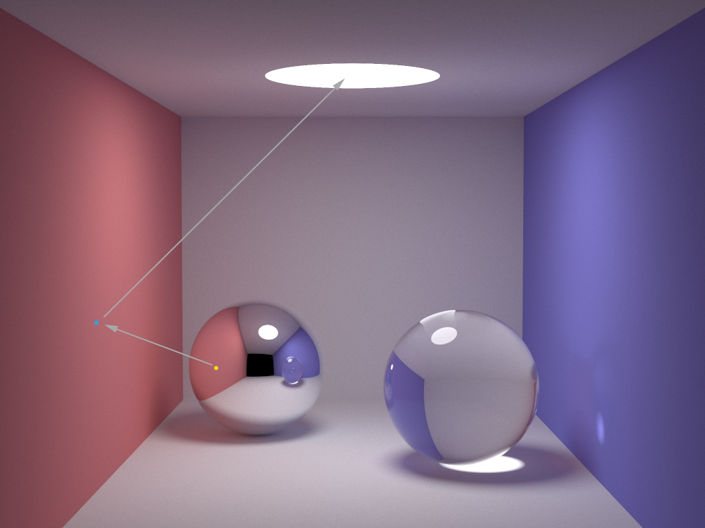
take the scenario shown in the following figure as an example. The following figure renders a 3D scene with 1024 * 768 pixels. The light source is located at the top. The sphere on the left is made of mirror material and the sphere on the right is made of glass. Assuming that the pixel of the yellow spot on the left ball is raytraced, the light first starts from the pixel of the yellow spot, falls on the left ball, falls on the blue spot on the left red wall after reflection, and finally reflects to the light source at the top again. Because the ball is made of mirror material, the ball will fully reflect the color of the wall, Therefore, the color of the pixel at the yellow dot is consistent with the color of the left wall. The ray tracing path is shown by the arrow in the following figure:
Overview of ray tracing algorithm
according to the ray tracing principle described above, we can deduce the proposed framework of ray tracing, which can be summarized into pseudo code:
for each pixel do :
    compute viewing ray
    if (ray hits an object) then :
        get hit object ID
        compute reflected ray
        evaluate shading model
        recursively trace ray back until stop
        set pixel to shading color
    else :
        set shading color to background color
the general process is:
Generate initial ray
to generate light, the mathematical expression of light is necessary. Light is a directed ray produced by a light source. Based on this principle, any light can be mathematically represented by the source point of the light and the propagation direction of the light. The following formula can be obtained:
P ( t ) ⃗ = e ⃗ + t ⋅ d ⃗ t ∈ ( 0 , ∞ ) (1) \vec{P(t)} = \vec{e} + t \cdot \vec{d} \qquad t\in(0,\infty) \tag{1} P(t) =e +t⋅d t∈(0,∞)(1)
where
e
⃗
\vec{e}
e
Is the three-dimensional coordinates of the light source point,
d
⃗
\vec{d}
d
Is the direction unit vector of the light,
t
t
t is a scalar that represents the edge
d
⃗
\vec{d}
d
The distance from the source point in the direction. The whole formula indicates that the distance from the source point on the ray path is
t
t
t, and the sum of all points on the light path constitutes the light itself.
after having the mathematical expression of light, the position and direction of the initial light can be calculated, but the values of these two are not set arbitrarily. Calculating the values of these two involves another problem, that is, the problem of viewing angle.
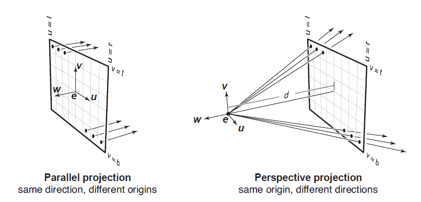
in the field of computer graphics, there are two main perspectives, namely, orthogonal view (also known as Parallel View) and Perspective View. In the orthogonal angle of view, the imaging of the object is mapped on the corresponding pixel points in a way perpendicular to the imaging plane, so the directions of all initial rays are the same and perpendicular to the imaging plane, and the starting point is on the corresponding pixel points of the imaging plane.
for the imaging with perspective angle closer to the human eye, all initial rays are emitted from one point, which is usually called the Viewing Point, while the imaging surface is located in front of the viewpoint. All initial rays Start from the viewpoint and then pass through the pixel points of the corresponding imaging surface. Therefore, in perspective, the direction of light is different and presents a radial distribution. The difference of initial light between the two viewing angles can be seen in the comparison below:
therefore, for any pixel p ⃗ = ( x , y , z ) \vec{p}=(x,y,z) p = (x,y,z), the initial light in the orthogonal angle of view can be expressed as:
r a y . p o s i t i o n = p ⃗ ray.position = \vec{p} ray.position=p r a y . d i r e c t i o n = − w ⃗ (2) ray.direction = -\vec{w} \tag{2} ray.direction=−w (2)
the initial light in perspective can be expressed as:
r a y . p o s i t i o n = e ⃗ ray.position = \vec{e} ray.position=e r a y . d i r e c t i o n = − d ∗ w ⃗ + x ∗ u ⃗ + y ∗ v ⃗ ray.direction = -d*\vec{w} \ + \ x*\vec{u} \ + \ y*\vec{v} ray.direction=−d∗w + x∗u + y∗v
among them,
p
⃗
\vec{p}
p
Is the three-dimensional coordinates of pixels,
u
⃗
,
v
⃗
,
w
⃗
\vec{u} ,\ \vec{v} ,\ \vec{w}
u
, v
, w
They are the coordinate system established based on the imaging surface, right, upward and outward unit vectors.
e
⃗
\vec{e}
e
Is the three-dimensional coordinates of the viewpoint,
d
d
d is the distance from the viewpoint to the imaging surface.
in order to facilitate calculation, the algorithm shared in this blog adopts orthogonal perspective.
Light intersects with objects
the second problem to be solved in ray tracing is to judge whether the ray intersects with the object in space. Similarly, we need to establish the mathematical expression of the object in three-dimensional space in order to further calculate it.
in the current field of computer graphics, the intersection processing of light and object is mainly concentrated on sphere and triangle. It's easy to understand the sphere, but why use the triangle? Triangular surface is the lightest expression of all mathematical expressions of three-dimensional plane. Any polytropic surface can be composed of several triangular surfaces. By analogy, any object in three-dimensional space (actually including sphere) can be composed of multiple triangular surfaces, that is, by combining triangular surfaces, we can get any object in space.
but some fine models often have thousands or even tens of thousands of triangles. Ray tracing such an object will consume a lot of time and computational power. The scene in Figure 1 in this article is the final effect picture after rendering for 10 + hours. For the purpose of simplifying calculation, the algorithm of this blog only involves the intersection of light and sphere.
if the ball center is known
C
C
Coordinates of C
(
x
c
,
y
c
,
z
c
)
(x_c, \ y_c, \ z_c )
(xc, yc, zc), radius of the ball
R
R
R. Then any point on the sphere
P
P
The coordinates of P can be expressed by the following formula:
( x − x c ) 2 + ( y − y c ) 2 + ( z − z c ) 2 = R 2 (x-x_c)^2 \ + \ (y-y_c)^2 \ + \ (z-z_c)^2 = R^2 (x−xc)2 + (y−yc)2 + (z−zc)2=R2
or use vector expression directly:
( P ⃗ − C ⃗ ) ⋅ ( P ⃗ − C ⃗ ) = R 2 (3) (\vec{P}-\vec{C}) \cdot (\vec{P}-\vec{C}) = R^2 \tag{3} (P −C )⋅(P −C )=R2(3)
the sum of all points on the sphere constitutes the sphere itself. The intersection of light and sphere is actually the intersection of light and a point on the sphere. In the previous part, we have obtained the expression of light. Replace equation (2) into equation (3), and the expression of intersection is:
( e ⃗ + t ⋅ d ⃗ − C ⃗ ) ⋅ ( e ⃗ + t ⋅ d ⃗ − C ⃗ ) − R 2 = 0 (4) (\vec{e} + t \cdot \vec{d}-\vec{C}) \cdot (\vec{e} + t \cdot \vec{d}-\vec{C}) - R^2 = 0 \tag{4} (e +t⋅d −C )⋅(e +t⋅d −C )−R2=0(4)
further simplification can be obtained:
( d ⃗ ⋅ d ⃗ ) ∗ t 2 + ( e ⃗ − C ⃗ ) ⋅ d ⃗ ∗ 2 t + ( e ⃗ − C ⃗ ) ⋅ ( e ⃗ − C ⃗ ) − R 2 = 0 (5) (\vec{d} \cdot \vec{d})*t^2 + (\vec{e}-\vec{C}) \cdot \vec{d}*2t + (\vec{e}-\vec{C}) \cdot (\vec{e}-\vec{C}) - R^2 = 0 \tag{5} (d ⋅d )∗t2+(e −C )⋅d ∗2t+(e −C )⋅(e −C )−R2=0(5)
observing the expression, we can find that this is about t t The univariate quadratic equation of t, where“ ⋅ \cdot ⋅ "is dot multiplication“ ∗ * * "is number multiplication, equation coefficient a , b , c a, \ b, \ c a. b and c are respectively:
a = ( d ⃗ ⋅ d ⃗ ) a = (\vec{d} \cdot \vec{d}) a=(d ⋅d ) b = ( e ⃗ − C ⃗ ) ⋅ d ⃗ ∗ 2 b = (\vec{e}-\vec{C}) \cdot \vec{d}*2 b=(e −C )⋅d ∗2 c = ( e ⃗ − C ⃗ ) ⋅ ( e ⃗ − C ⃗ ) − R 2 c = (\vec{e}-\vec{C}) \cdot (\vec{e}-\vec{C}) - R^2 c=(e −C )⋅(e −C )−R2
obtained by solving the equation t t t is the distance from the source point to the intersection point of the light. It should be noted that t t t cannot be negative (negative means that the light is emitted in the opposite direction, and d ⃗ \vec{d} d In addition, the value should also be limited to a certain range, not positive infinity. last t t t should be the smaller one, because the ray passing through the sphere actually has two intersections with the sphere, and only the intersection close to the source point is the actual intersection of the light.
Light reflection
after the initial light intersects with the object, it will not stop, but will reflect and refract according to the material of the object. However, due to the complexity of the algorithm implementation of light refraction (actually my dish), the algorithm of this blog only involves the reflection of light.
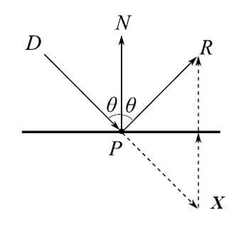
the reflection of light can be divided into specular reflection and diffuse reflection. Specular reflection is relatively simple. When the light intersects with the object at a certain incident angle, the reflected light is also emitted at the same angle. As shown in the figure below, the required direction of reflected light
P
R
⃗
\vec{PR}
PR
, available from
P
X
⃗
+
X
R
⃗
\vec{PX}+\vec{XR}
PX
+XR
Obtain, where
P
X
⃗
\vec{PX}
PX
By the direction of incident light
D
P
⃗
\vec{DP}
DP
The displacement is obtained,
P
N
⃗
\vec{PN}
PN
Is the normal vector of the plane,
X R ⃗ = 2 ( P D ⃗ ∗ cos θ ) = 2 ( − D P ⃗ ∗ cos θ ) = − 2 ( D P ⃗ ⋅ P N ⃗ ) / ( ∣ D P ⃗ ∣ ∗ ∣ P N ⃗ ∣ ) \vec{XR} = 2(\vec{PD}*\cos{\theta}) = 2(-\vec{DP}*\cos{\theta}) = -2(\vec{DP} \cdot \vec{PN})/(\vert\vec{DP}\vert*\vert\vec{PN}\vert) XR =2(PD ∗cosθ)=2(−DP ∗cosθ)=−2(DP ⋅PN )/(∣DP ∣∗∣PN ∣)
due to D P ⃗ , P N ⃗ , P R ⃗ \vec{DP}, \ \vec{PN}, \ \vec{PR} DP , PN , PR Are unit vectors, so the direction of reflected light can be obtained as follows:
P R ⃗ = D P ⃗ − 2 ( D P ⃗ ⋅ P N ⃗ ) (6) \vec{PR}=\vec{DP}-2(\vec{DP} \cdot \vec{PN}) \tag{6} PR =DP −2(DP ⋅PN )(6)
the biggest difference between diffuse reflection and specular reflection is that the incident angle and exit angle of diffuse reflection are different. Therefore, in ray tracing algorithm, the direction of exit angle is generally randomly generated. To randomly generate the outgoing light, we first need to establish an orthogonal coordinate system for the outgoing light. Normal vector of plane
n
⃗
\vec{n}
n
Is the first axis of the coordinate system, and the second axis should be perpendicular to the normal vector. Therefore, it can be obtained by cross multiplication of a unit vector and the normal vector, that is:
u ⃗ = n ⃗ × v e c ⃗ \vec{u} = \vec{n} \times \vec{vec} u =n ×vec
The third axis needs to be perpendicular to the first and second axes, so it can be obtained by cross multiplying the first and second axes. Namely:
v ⃗ = n ⃗ × u ⃗ \vec{v} = \vec{n} \times \vec{u} v =n ×u
Finally, the three axes are unit vectors, so the randomly generated reflected light can be obtained by randomly setting the extension of light on each axis.
shading model
if only calculating the intersection of light and object is not enough to render a complete picture, the imaging image needs to be colored according to the color of the object. Shading requires a shading model.
the simplest coloring model was proposed by Lanbert in the 18th century based on observations in daily life. He believes that in the unit area, the amount of light that can be gathered by the plane depends on the angle of light entering the plane, so he puts forward the Lanbert coloring model:
L = k d ∗ I ∗ m a x ( 0 , n ⃗ ⋅ l ⃗ ) (7) L = k_d*I*max(0, \ \vec{n} \cdot \vec{l}) \tag{7} L=kd∗I∗max(0, n ⋅l )(7)
among them,
k
d
k_d
kd = diffuse reflection coefficient,
I
I
I is the light source,
n
⃗
\vec{n}
n
And
l
⃗
\vec{l}
l
They are plane normal vector and reflected ray direction respectively (ray tracing is the inverse process of illumination, so the reflected ray direction is the direction of light emitted by the light source),
L
L
L is the color of the current pixel, which can be either scalar or vector (if three channel vector is used to represent RGB color).
however, the effect of the lighting model is very rough. The colors of the same object are basically the same everywhere, with neither highlights nor light and shade changes. In view of this situation, Phong and Blinn proposed in 1975 that when the angular bisector of the incident angle and exit angle of light is closer to the normal vector of the plane, the more light can be reflected by the plane. Therefore, the Phong Blinn coloring model is evolved based on the Lanbert coloring model:
L = k d ∗ I ∗ m a x ( 0 , n ⃗ ⋅ l ⃗ ) + k s ∗ I ∗ m a x ( 0 , n ⃗ ⋅ h ⃗ ) p (7) L = k_d*I*max(0, \ \vec{n} \cdot \vec{l}) + k_s*I*max(0, \ \vec{n} \cdot \vec{h})^p \tag{7} L=kd∗I∗max(0, n ⋅l )+ks∗I∗max(0, n ⋅h )p(7) h ⃗ = ( v ⃗ ⋅ l ⃗ ) / ∥ v ⃗ + l ⃗ ∥ \vec{h} = (\vec{v} \cdot \vec{l})/\Vert\vec{v}+\vec{l}\Vert h =(v ⋅l )/∥v +l ∥
among k s k_s ks = specular reflection coefficient, h ⃗ \vec{h} h Is the angular bisector of the incident light and the outgoing light, p p The value of Phong is used to control the amount of light reflection, which cannot be less than 1. When p p The smaller the p, the closer the reflection mechanism is to diffuse reflection, p p The larger p is, the closer the reflection mechanism is to specular reflection.
Code explanation
this section will introduce in detail the code of ray tracing algorithm based on the contents of the above sections. The code is mainly composed of three sections. The first section is user-defined components, including user-defined structures and tool functions; The second part is the main loop of the algorithm; The third plate is ray tracing and coloring.
Custom components
the custom component defines three types of structures: Vector3, Ray, Sphere, and five tool functions Random(), Max(), ToInt(), Clamp(), IsIntersect().
- Vector3 structure
As the name suggests, this structure is used to represent three-dimensional vectors and defines the basic operations of vectors, such as number multiplication, contraposition multiplication, point multiplication, cross multiplication, modulus taking, unit vector taking, etc
struct Vector3 {
    double x, y, z;
    Vector3 (double x_ = 0, double y_ = 0, double z_ = 0) {
        x = x_;
        y = y_;
        z = z_;
    }

    Vector3 operator+ (Vector3 vec) { return Vector3(x+vec.x, y+vec.y, z+vec.z);}

    Vector3 operator- (Vector3 vec) { return Vector3(x-vec.x, y-vec.y, z-vec.z);}

    Vector3 operator* (double scalar) { return Vector3(x*scalar, y*scalar, z*scalar);}

    Vector3 operator% (double scalar) { return Vector3(x/scalar, y/scalar, z/scalar);}

    Vector3 Mul (Vector3 vec) { return Vector3(x*vec.x, y*vec.y, z*vec.z);}

    double Dot (Vector3 vec) { return x*vec.x + y*vec.y + z*vec.z;}

    Vector3 Cross (Vector3 vec) { return Vector3(y*vec.z - z*vec.y, z*vec.x - x*vec.z, x*vec.y - y*vec.x);}

    Vector3 Norm() { return sqrt(x*x + y*y + z*z);}

    Vector3 UnitVector () {
        double norm = sqrt(x*x + y*y + z*z);
        return Vector3(x/norm, y/norm, z/norm);
    }
};
- Ray structure
The light structure is not detailed here due to its simple composition
struct Ray {
    Vector3 position, direction;
    Ray (Vector3 position_, Vector3 direction_) {
        position = position_;
        direction = direction_;
    }
};
- Sphere structure
Sphere structure. In addition to the two attributes of sphere center and radius, the sphere also needs to have color and material. In addition, the solution of equation (5) is encapsulated as the member function of the sphere structure to detect the intersection relationship between the light and the current sphere.
struct Sphere {
    double radius;
    Vector3 position, color;
    Material material;

    Sphere (Vector3 position_, double radius_, Vector3 color_, Material material_) {
        position = position_;
        radius = radius_;
        color = color_;
        material = material_;
    }

    double Intersection (Ray ray) {
        // solving: (d.d)*t*t - [d.(e-c)]*2*t + (e-c).(e-c) - R*R = 0
        Vector3 e2c = ray.position - position;       // the vector between ray origin and sphere center, (e-c)
        double eps = 1e-4;
        double a = ray.direction.Dot(ray.direction); // d is a unit vector, hence d.d = 1
        double b = ray.direction.Dot(e2c) * 2;       // d.(e-c)
        double c = e2c.Dot(e2c) - radius*radius;     // (e-c).(e-c) - R*R
        double det = b*b - a*c*4;

        if (det < 0) { return 0; }

        // solving t
        double ans1 = (-b + sqrt(det)) / 2*a;
        double ans2 = (-b - sqrt(det)) / 2*a;
        return (ans2)>eps ? ans2 : (ans1>eps ? ans1 : 0);
    }
};
in the scene set by this algorithm, the imaging plane is
1000
∗
1000
p
x
1000*1000px
1000 * 1000px, the lower left vertex of the plane is the origin
(
0
,
0
,
0
)
(0, \ 0, \ 0)
(0, 0, 0), so as to establish a rectangular coordinate system, right is
x
x
Positive direction of x-axis, upward is
y
y
Positive direction of y-axis, forward is
z
z
Positive direction of z axis. On this premise, 12 spheres are defined in the scene. Among them, spheres 0 ~ 5 are the walls of the scene. When the sphere is very large relative to the scene, the sphere can be approximately regarded as a plane (the same reason we think the ground is flat when standing on the earth). Therefore, the radius of spheres 0 ~ 5 is set to 100000. Then, spheres 6 ~ 10 are obstacles in the scene, of which spheres 6 ~ 8 are mirror materials and spheres 9 ~ 10 are rough materials. Finally, sphere 11 is the light source of the scene.
Sphere spheres[] = {//Scene: position, radius, color, material
    // Sphere(Vector3(0,  0,        6),        5,  Vector3(.75, .25, .25), DIFF),
    Sphere(Vector3(-1e5+1.25,  500,        500),        1e5, Vector3(.75, .25, .25), DIFF),   //Left 0
    Sphere(Vector3(1e5+998.75, 500,        500),        1e5, Vector3(.25, .25, .75), DIFF),   //Rght 1
    Sphere(Vector3(500,        500,        1e5+998.75), 1e5, Vector3(.75, .75, .75), DIFF),   //Back 2
    Sphere(Vector3(500,        500,        -1e5),       1e5, Vector3(             ), DIFF),   //Frnt 3
    Sphere(Vector3(500,        -1e5+1.25,  500),        1e5, Vector3(.75, .75, .75), DIFF),   //Botm 4
    Sphere(Vector3(500,        1e5+998.75, 500),        1e5, Vector3(.75, .75, .75), DIFF),   //Top  5
    Sphere(Vector3(150,        400,        100),        100, Vector3(1, 1, 1)*.999,  SPEC),   //Mirr 6
    Sphere(Vector3(350,        200,        110),        100, Vector3(1, 1, 1)*.999,  SPEC),   //Mirr 7
    Sphere(Vector3(350,        800,        110),        100, Vector3(1, 1, 1)*.999,  SPEC),   //Mirr 8
    Sphere(Vector3(600,        500,        110),        100, Vector3(1, 1, 1)*.999,  DIFF),   //Norm 9
    Sphere(Vector3(850,        750,        450),        100, Vector3(1, 1, 1)*.999,  DIFF),   //Norm 10
    Sphere(Vector3(500,        1e5+998,    500),        1e5, Vector3(),              DIFF)    //Light 11

};
- Random(), Max() function
These two tool functions are relatively simple, so they will not be detailed.
double Random() {
    return (double)rand() / (double)RAND_MAX;
}

double Max(double x, double y) {
    return x > y ? x : y;
}
- ToInt(), Clamp() function
In the calculation process of the algorithm, all color related values are double precision floating-point numbers. Therefore, ToInt() tool function is required to convert floating-point numbers in the range of 0 ~ 1 into integers in the range of 0 ~ 255. The original data is out of bounds, so the Clamp() tool function is needed to intercept the redundant part of the data.
double Clamp (double x) {
    return x < 0 ? 0 : x > 1 ? 1 : x;               // CLAMP function,  0 < x < 1
}

int ToInt (double x) {								// convert floats to integers to be save in ppm file, 2.2 is gamma correction
    return int(pow(Clamp(x), 1/2.2) * 255 + 0.5);
}
- IsIntersect() function
IsIntersect() is responsible for judging whether the light intersects with the objects in the scene. This function will traverse the objects in the scene one by one and calculate by calling the sphere's own intersection detection function t t t. Finally, the number of the first object intersecting with the light and t t The value of t.
bool IsIntersect (Ray ray, double &t, int &id) {
    int sphere_num = sizeof(spheres) / sizeof(Sphere);
    double temp;
    double inf = 1e20;
    t = inf;

    for (int i = 0; i < int(sphere_num); i++) {
        temp = spheres[i].Intersection(ray);
        if(temp != 0 && temp < t) {                 // compute the closest intersection
            t = temp;
            id = i;
        }
    }
    return t < inf;
}
Algorithm main loop
the main loop not only traverses all pixels of the imaging plane, but also controls each pixel
2
×
2
2 \times 2
two × 2 sampling, used for carrying sawtooth to a certain extent. For each sampling point, ray tracing is performed once. Finally, the colors of the four sampling points are averaged and accumulated to get the color of the current pixel.
 Vector3 origin(0.0, 0.0, 0.0);
 Vector3 direction(0.0, 0.0, 1.0);
 Vector3 *image = new Vector3[width * hight];

 /* main ray tracing loop */
 for (int row = 0; row < hight; row++) {                     // looping over image rows
     for (int col = 0; col < width; col++) {                 // looping over image colomns
         int index = (hight-row-1)*width + col;              // map 2D pixel location to 1D vector
         Vector3 pixel_color(0.0, 0.0, 0.0);

         for (int srow = 0; srow < 2; srow++) {              // looping over 2x2 subsample rows
             for (int scol = 0; scol < 2; scol ++) {         // looping over 2x2 subsample colomns
                 Vector3 offset(double(row)+double(srow), double(col)+double(scol), 0.0);
                 Ray camera(offset, direction);
                 int depth = 0;

                 pixel_color = pixel_color + TracingAndShading(camera, depth) * 0.25;
             }
         }
         image[index] = image[index] + Vector3(Clamp(pixel_color.x), Clamp(pixel_color.y), Clamp(pixel_color.z));
     }
 }

 FILE *file = fopen("image.ppm", "w");
 fprintf(file, "P3\n%d %d\n%d\n", width, hight, 255);
 for (int i = 0; i < width*hight; i++) {
     fprintf(file, "%d %d %d ", ToInt(image[i].x), ToInt(image[i].y), ToInt(image[i].z));
 }
Raytracing and shading
the algorithm will first judge whether the light intersects with the objects in the scene. If the light does not intersect with any objects, it indicates that the light does not exist and directly returns a value of all
−
1
-1
The vector of − 1 represents this situation. It then determines whether the light intersects the light source. If yes, it indicates that the ray tracing has reached the end point and returns directly. If not, it will be further processed according to the material of the object.
Vector3 TracingAndShading (Ray ray, int depth) {
    double t;
    int id = 0;
    depth ++;

    if (depth > 15) {
        return Vector3(-1.0, -1.0, -1.0);           // ray can reflect for 15 times in maximum, if larger than 15, assume the ray is not from light source
    }
    if (IsIntersect(ray, t, id) == false) {         // if not hit any object, which means the ray is from the void
        return Vector3(-1.0, -1.0, -1.0);
    }
    if (id == 11) {                                 // if hits light source, end ray tracing recursion
        return Vector3();
    }

    Sphere obj = spheres[id];
    Vector3 p = ray.position + ray.direction * t;       // ray-sphere hit point
    Vector3 n = (p - obj.position).UnitVector();        // sphere normal vector at hit point
    Vector3 nl = n.Dot(ray.direction) < 0 ? n : n*-1;   // properly oriented sphere normal vector, telling the ray in entering or exiting.
if the object is made of rough material, calculate the reflected light according to the diffuse reflection mode, and then recursively calculate the ray tracing and coloring of the reflected light, then calculate the accumulated color according to equation (7) between the recursive color and the color of the current object, and finally return to the color.
    if (obj.material == DIFF) {                         // ideal diffusive reflaction
        double r1 = 2 * M_PI * Random();                // angle around
        double r2 = Random();                           // distance from center

        Vector3 w = nl;                                 // w = sphere normal
        Vector3 u = ((fabs(w.x) > 0.1 ? Vector3(0,1) : Vector3(1)).Cross(w)).UnitVector();  // u is perpendicular to w
        Vector3 v = w.Cross(u);                                                             // v is perpendicular to w and v
        Vector3 d = (u*cos(r1)*sqrt(r2) + v*sin(r1)*sqrt(r2) + w*sqrt(1-r2)).UnitVector();  // random generated reflection ray direction
        Vector3 h = (ray.direction*-1 + d).UnitVector();                                    // the vector of bisector of origin ray and reflected ray

        Ray reflect_ray(p, d);
        Vector3 reflect_color = TracingAndShading(reflect_ray, depth);
        if (reflect_color.x == -1.0) {                  // if the ray is not from light source
            return reflect_color;
        }
        return obj.color*kd*Max(0, n.Dot(d)) + obj.color*ks*Max(0, n.Dot(h)) + reflect_color*lambda;
    }
if the object is made of specular material, calculate the reflected light according to the specular reflection mode, and then perform ray tracing coloring on the reflected light recursively, and finally return the accumulated color.
    // ideal specular reflaction
    Vector3 d = ray.direction - n*2*n.Dot(ray.direction);
    Ray reflect_ray(p, d);
    Vector3 reflect_color = TracingAndShading(reflect_ray, depth);
    if (reflect_color.x == -1.0) {
        return reflect_color;
    }
    return obj.color*kd*Max(0, n.Dot(d)) + obj.color*ks + reflect_color*lambda;
it should be noted that the light may not be reflected to the light source regardless of the reflection. Therefore, in this algorithm, if the recursion depth exceeds 15 layers, it is determined that the light does not exist. In practical application, the recursion limit can be much larger than 15 layers. 15 layers are set here only to save time and computational power.
Complete code
#include <math.h>
#include <ctime>
#include <cstdlib>
#include <stdlib.h>
#include <stdio.h>

#include <iostream>

// global coefficient
double kd = 0.6;                        // diffuse coefficient
double ks = 0.6;                        // specular coefficient
double lambda = 0.001;                  // reflect decay coefficient
enum Material { DIFF, SPEC, REFR };     // reflection type, DIFF = diffusive, SPEC = specular, REFR = refractive


struct Vector3
{
    double x, y, z;
    Vector3 (double x_ = 0, double y_ = 0, double z_ = 0) {
        x = x_;
        y = y_;
        z = z_;
    }

    Vector3 operator+ (Vector3 vec) { return Vector3(x+vec.x, y+vec.y, z+vec.z);}

    Vector3 operator- (Vector3 vec) { return Vector3(x-vec.x, y-vec.y, z-vec.z);}

    Vector3 operator* (double scalar) { return Vector3(x*scalar, y*scalar, z*scalar);}

    Vector3 operator% (double scalar) { return Vector3(x/scalar, y/scalar, z/scalar);}

    Vector3 Mul (Vector3 vec) { return Vector3(x*vec.x, y*vec.y, z*vec.z);}

    double Dot (Vector3 vec) { return x*vec.x + y*vec.y + z*vec.z;}

    Vector3 Cross (Vector3 vec) { return Vector3(y*vec.z - z*vec.y, z*vec.x - x*vec.z, x*vec.y - y*vec.x);}

    Vector3 Norm() { return sqrt(x*x + y*y + z*z);}

    Vector3 UnitVector () {
        double norm = sqrt(x*x + y*y + z*z);
        return Vector3(x/norm, y/norm, z/norm);
    }
};


struct Ray
{
    Vector3 position, direction;
    Ray (Vector3 position_, Vector3 direction_) {
        position = position_;
        direction = direction_;
    }
};

struct Sphere
{
    double radius;
    Vector3 position, color;
    Material material;

    Sphere (Vector3 position_, double radius_, Vector3 color_, Material material_) {
        position = position_;
        radius = radius_;
        color = color_;
        material = material_;
    }

    double Intersection (Ray ray) {
        // solving: (d.d)*t*t - [d.(e-c)]*2*t + (e-c).(e-c) - R*R = 0
        Vector3 e2c = ray.position - position;       // the vector between ray origin and sphere center, (e-c)
        double eps = 1e-4;
        double a = ray.direction.Dot(ray.direction); // d is a unit vector, hence d.d = 1
        double b = ray.direction.Dot(e2c) * 2;       // d.(e-c)
        double c = e2c.Dot(e2c) - radius*radius;     // (e-c).(e-c) - R*R
        double det = b*b - a*c*4;

        if (det < 0) { return 0; }

        // solving t
        double ans1 = (-b + sqrt(det)) / 2*a;
        double ans2 = (-b - sqrt(det)) / 2*a;
        return (ans2)>eps ? ans2 : (ans1>eps ? ans1 : 0);
    }
};


Sphere spheres[] = {//Scene: position, radius, color, material
    // Sphere(Vector3(0,  0,        6),        5,  Vector3(.75, .25, .25), DIFF),
    Sphere(Vector3(-1e5+1.25,  500,        500),        1e5, Vector3(.75, .25, .25), DIFF),   //Left 0
    Sphere(Vector3(1e5+998.75, 500,        500),        1e5, Vector3(.25, .25, .75), DIFF),   //Rght 1
    Sphere(Vector3(500,        500,        1e5+998.75), 1e5, Vector3(.75, .75, .75), DIFF),   //Back 2
    Sphere(Vector3(500,        500,        -1e5),       1e5, Vector3(             ), DIFF),   //Frnt 3
    Sphere(Vector3(500,        -1e5+1.25,  500),        1e5, Vector3(.75, .75, .75), DIFF),   //Botm 4
    Sphere(Vector3(500,        1e5+998.75, 500),        1e5, Vector3(.75, .75, .75), DIFF),   //Top  5
    Sphere(Vector3(150,        400,        100),        100, Vector3(1, 1, 1)*.999,  SPEC),   //Mirr 6
    Sphere(Vector3(350,        200,        110),        100, Vector3(1, 1, 1)*.999,  SPEC),   //Mirr 7
    Sphere(Vector3(350,        800,        110),        100, Vector3(1, 1, 1)*.999,  SPEC),   //Mirr 8
    Sphere(Vector3(600,        500,        110),        100, Vector3(1, 1, 1)*.999,  DIFF),   //Norm 9
    Sphere(Vector3(850,        750,        450),        100, Vector3(1, 1, 1)*.999,  DIFF),   //Norm 10
    Sphere(Vector3(500,        1e5+998,    500),        1e5, Vector3(),              DIFF)    //Light 11

};


double Random() {
    return (double)rand() / (double)RAND_MAX;
}


double Max(double x, double y) {
    return x > y ? x : y;
}


double Clamp (double x) {
    return x < 0 ? 0 : x > 1 ? 1 : x;               // CLAMP function,  0 < x < 1
}


int ToInt (double x) {
    return int(pow(Clamp(x), 1/2.2) * 255 + 0.5);   // convert floats to integers to be save in ppm file, 2.2 is gamma correction
}


bool IsIntersect (Ray ray, double &t, int &id) {
    int sphere_num = sizeof(spheres) / sizeof(Sphere);
    double temp;
    double inf = 1e20;
    t = inf;

    for (int i = 0; i < int(sphere_num); i++) {
        temp = spheres[i].Intersection(ray);
        if(temp != 0 && temp < t) {                 // compute the closest intersection
            t = temp;
            id = i;
        }
    }
    return t < inf;
}


Vector3 TracingAndShading (Ray ray, int depth) {

    double t;
    int id = 0;
    depth ++;

    if (depth > 15) {
        return Vector3(-1.0, -1.0, -1.0);           // ray can reflect for 15 times in maximum, if larger than 15, assume the ray is not from light source
    }
    if (IsIntersect(ray, t, id) == false) {         // if not hit any object, which means the ray is from the void
        return Vector3(-1.0, -1.0, -1.0);
    }
    if (id == 11) {                                 // if hits light source, end ray tracing recursion
        return Vector3();
    }

    Sphere obj = spheres[id];
    Vector3 p = ray.position + ray.direction * t;       // ray-sphere hit point
    Vector3 n = (p - obj.position).UnitVector();        // sphere normal vector at hit point
    Vector3 nl = n.Dot(ray.direction) < 0 ? n : n*-1;   // properly oriented sphere normal vector, telling the ray in entering or exiting.

    if (obj.material == DIFF) {                         // ideal diffusive reflaction
        double r1 = 2 * M_PI * Random();                // angle around
        double r2 = Random();                           // distance from center

        Vector3 w = nl;                                 // w = sphere normal
        Vector3 u = ((fabs(w.x) > 0.1 ? Vector3(0,1) : Vector3(1)).Cross(w)).UnitVector();  // u is perpendicular to w
        Vector3 v = w.Cross(u);                                                             // v is perpendicular to w and v
        Vector3 d = (u*cos(r1)*sqrt(r2) + v*sin(r1)*sqrt(r2) + w*sqrt(1-r2)).UnitVector();  // random generated reflection ray direction
        Vector3 h = (ray.direction*-1 + d).UnitVector();                                    // the vector of bisector of origin ray and reflected ray

        Ray reflect_ray(p, d);
        Vector3 reflect_color = TracingAndShading(reflect_ray, depth);
        if (reflect_color.x == -1.0) {                  // if the ray is not from light source
            return reflect_color;
        }
        return obj.color*kd*Max(0, n.Dot(d)) + obj.color*ks*Max(0, n.Dot(h)) + reflect_color*lambda;
    }

    // ideal specular reflaction
    Vector3 d = ray.direction - n*2*n.Dot(ray.direction);
    Ray reflect_ray(p, d);
    Vector3 reflect_color = TracingAndShading(reflect_ray, depth);
    if (reflect_color.x == -1.0) {
        return reflect_color;
    }
    return obj.color*kd*Max(0, n.Dot(d)) + obj.color*ks + reflect_color*lambda;

    /* ideal dielectric refraction */
    // Ray reflect_ray = (p, ray.direction - n*2*n.Dot(ray.direction));
    // bool into = n.Dot(nl) > 0;                  // ray from outside going in?
    // double nc = 1;
    // double nt = 1.5;
    // double nnt = into ? nc/nt : nt/nc;
    // double ddn = ray.direction.Dot(nl);
    // double cos2t = 1 - nnt*nnt(1-ddn*ddn);

    // if (cos2t < 0) {                            // total internal reflection
    //     Vector3 reflect_color = TracingAndShading(reflect_ray, depth);
    //     if (reflect_color.x == -1.0) {
    //         return reflect_color;
    //     }
    //     return obj.color*kd + obj.color*ks + reflect_color*lambda;
    // }

    // Vector3 tdir = (ray.direction*nnt - n*((into?1:-1)*(ddn*nnt + sqrt(cos2t)))).UnitVector();
    // double a = nt - nc;
    // double b = nt + nc;
    // double c = 1 - (into ? -ddn : tdir.Dot(n));
    // double R0 = a*a/(b*b);
    // double Re = R0 + (1-R0)*c*c*c*c*c;
    // double Tr = 1 - Re;
    // double P = 0.25 + 0.5*Re;
    // double RP = Re / P;
    // double TP = Tr / (1-P);

    // return obj.color*kd + obj.color*ks + (depth > 2 ? (Random < P ?
    //     TracingAndShading(reflect_ray, depth)*RP : TracingAndShading(Ray(p,tdir), depth)*TP) :
    //     TracingAndShading(reflect_ray, depth)*Re + TracingAndShading(Ray(p,tdir), depth)*Tr);
}


int main(int argc, char* argv[]) {
    int hight = 1000;
    int width = 1000;
    unsigned seed = time(0);
    srand(seed);

    Vector3 origin(0.0, 0.0, 0.0);
    Vector3 direction(0.0, 0.0, 1.0);
    Vector3 *image = new Vector3[width * hight];

    /* main ray tracing loop */
    for (int row = 0; row < hight; row++) {                     // looping over image rows
        for (int col = 0; col < width; col++) {                 // looping over image colomns
            int index = (hight-row-1)*width + col;              // map 2D pixel location to 1D vector
            Vector3 pixel_color(0.0, 0.0, 0.0);

            for (int srow = 0; srow < 2; srow++) {              // looping over 2x2 subsample rows
                for (int scol = 0; scol < 2; scol ++) {         // looping over 2x2 subsample colomns
                    Vector3 offset(double(row)+double(srow), double(col)+double(scol), 0.0);
                    Ray camera(offset, direction);
                    int depth = 0;

                    pixel_color = pixel_color + TracingAndShading(camera, depth) * 0.25;
                }
            }
            image[index] = image[index] + Vector3(Clamp(pixel_color.x), Clamp(pixel_color.y), Clamp(pixel_color.z));
        }
    }

    FILE *file = fopen("image.ppm", "w");
    fprintf(file, "P3\n%d %d\n%d\n", width, hight, 255);
    for (int i = 0; i < width*hight; i++) {
        fprintf(file, "%d %d %d ", ToInt(image[i].x), ToInt(image[i].y), ToInt(image[i].z));
    }
}
Results display and summary
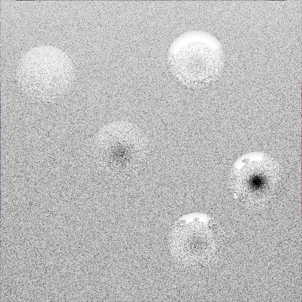
among them, balls 1, 2 and 3 are mirror shaders, and balls 4 and 5 are rough shaders
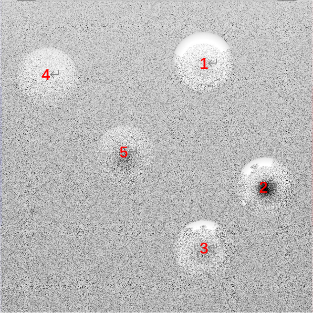
you can see that the sphere made of mirror material can well reflect the light source at the top. If you look carefully, you can also see the reflection of spheres in other positions.
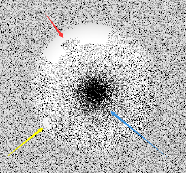
if you carefully observe sphere 2, the spot at the red arrow is the reflection of sphere 1, and the highlight at the yellow arrow is formed by the reflection of the highlight of sphere 3 on sphere 2. The dark spot of the blue arrow is because it faces the Frnt wall, which is black, so it shows black spots on sphere 2
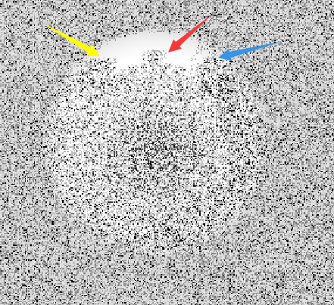
The spot at the arrow No. 5 is the reflection of the sphere, and the spot at the arrow No. 3 is the reflection of the sphere
and we can also observe that since sphere 4 is closer to the light source than sphere 5, the brightness of sphere 4 is higher than that of sphere 5.
generally speaking, the algorithm better realizes the basic function of ray tracing. If the number of samples, the number of recursive layers, and the area of the imaging image can be increased, and the color model can be further upgraded, the algorithm can get a better effect image.
the only drawback of the current rendering is that according to the original algorithm, the generated image should be RGB full-color image. However, I don't know why the final generated PPM file and the rendering converted from PPM file to PNG lose all color data, leaving only black and white color. If this problem can be solved, we can better analyze whether this algorithm can really accurately draw the original appearance of the scene, as well as the advantages and disadvantages of the algorithm itself.
reference
Peter, S., Steve, M. (2009). Fundamentals of Computer Graphics (3rd Edition)
Kevin, B. (2010). Smallpt: Global Illumination in 99 lines of C++. Retrieved from: http://www.kevinbeason.com/smallpt/
The original blog shall not be reproduced or copied