Asynchronous signal synchronization is a unique feature in the use of FPGA, and it is also a place that should be paid special attention to when coding in logic engineering. This paper only introduces the cross clock domain conversion of single bit slowly varying signal.
preface
The so-called slowly varying signal refers to the signal that satisfies Nyquist's sampling law.
The cross clock domain conversion of slow changing single BIT signal is often solved by beating with two or more D flip flops. However, in order to ensure that the compiler can comply with the wishes of programmers, the cross clock domain conversion code often needs some programming skills. The following takes Xilinx's application platform as an example.
1, RTL implementation mode
module async_in (
	 input	wire		src_in
	,input	wire		dest_clk
	,output	wire		dest_out
);
//==============================================================================================
//======                                  define signal                                 ========
//==============================================================================================
	(* ASYNC_REG="TRUE" *)		reg	[2:0]	sreg	;
//==============================================================================================
//======                                  initial	                                 	========
//==============================================================================================
	initial begin
		sreg = 3'b000;
	end
//==============================================================================================
//======                                  behave of RTL                                 ========
//==============================================================================================

	always@(posedge dest_clk)begin
		sreg <= {sreg[1:0], src_in};
	end

	assign dest_out = sreg[2];

endmodule
Description: ASYNC_REG is an attribute that affects many processes in the vivado tool process. The purpose of this attribute is to inform the tool that a register can receive asynchronous data relative to the source clock in the D input pin, or that the register is a synchronous register in the synchronization chain. Vivado synthesis. In this case, the attribute treats it as DONT_TOUCH attribute and set Async_ The reg attribute is pushed forward in the netlist. This process ensures async_ The object of reg attribute will not be optimized, and the tool later in the process will receive the attribute to handle it correctly.
Influence of "ASYNC_REG" attribute on Implementation
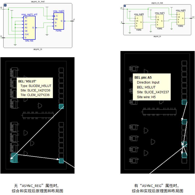
It can be seen that when there is "ASYNC_REG" attribute, after the implementation of the comprehensive tool, it is the same as our expected target design.
2, Implementation using primitives
module async_cdc(
	 input 	wire	src_in
	,input	wire	dest_clk
	,output	wire	dest_out
);
//==============================================================================================
//======                                  define signal                                 ========
//==============================================================================================
	(* keep = "TRUE" *)wire 	data_sync1;
	(* keep = "TRUE" *)wire 	data_sync2;
//==============================================================================================
//======                                  behave of RTL                                 ========
//==============================================================================================
	(* ASYNC_REG *)
	(* BOX_TYPE = "PRIMITIVE" *)
	(* SHREG_EXTRACT = "no" *)
	(* XILINX_LEGACY_PRIM = "FD" *)
	FDRE #(
		.INIT		(1'b0		)
	)data_sync_reg1(
		 .C			(dest_clk	)
        ,.CE		(1'b1		)
        ,.D			(src_in		)
        ,.Q			(data_sync1	)
        ,.R			(1'b0		)
	);
	//---------------------------------------------------------//
	(* ASYNC_REG *)
	(* BOX_TYPE = "PRIMITIVE" *)
	(* SHREG_EXTRACT = "no" *)
	(* XILINX_LEGACY_PRIM = "FD" *)
	FDRE #(
		.INIT		(1'b0		)
	)data_sync_reg2(
		 .C			(dest_clk	)
        ,.CE		(1'b1		)
        ,.D			(data_sync1	)
        ,.Q			(data_sync2	)
        ,.R			(1'b0		)
	);
	//---------------------------------------------------------//
	(* ASYNC_REG *)
	(* BOX_TYPE = "PRIMITIVE" *)
	(* SHREG_EXTRACT = "no" *)
	(* XILINX_LEGACY_PRIM = "FD" *)
	FDRE #(
		.INIT		(1'b0		)
	)data_sync_reg3(
		 .C			(dest_clk	)
        ,.CE		(1'b1		)
        ,.D			(data_sync2	)
        ,.Q			(dest_out	)
        ,.R			(1'b0		)
	);

endmodule
When using this module, you can constrain the asynchronous clock path in the XDC file. The constraint syntax is as follows:
set_false_path -to [get_cells -hierarchical -filter {NAME =~ *data_sync_reg1}]
3, Using Xilinx primitive xpm_*
xilinx's powerful ecological environment provides FPGA users with many library functions, including XPM for asynchronous signal synchronization_ CDC library, including:
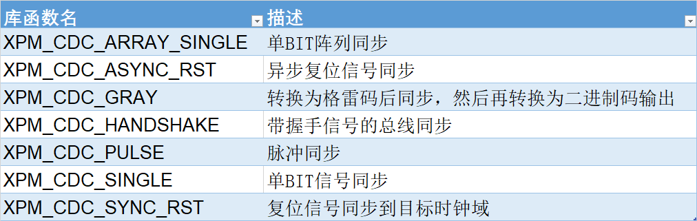
be careful:
XPM_CDC_SYNC_RST and XPM_ CDC_ ASYNC_ Unlike rst, both modules are used for synchronization of reset, but XPM_ CDC_ ASYNC_ When asserting, the reset signal output by RST is asynchronous with the target clock domain, and the release is synchronous; And XPM_ CDC_ SYNC_ The reset assertion and release of RST are synchronized with the target clock domain.
The following is XPM under Verilog_ CDC_* Modular template:
	//-----------------------------------------------------------//
	// xpm_cdc_async_rst: Asynchronous Reset Synchronizer
	//-----------------------------------------------------------//
	xpm_cdc_async_rst #(
		.DEST_SYNC_FF		(4),
		.INIT_SYNC_FF		(0),
		.RST_ACTIVE_HIGH	(0)
	)
	xpm_cdc_async_rst_inst (
		.src_arst			(power_reset	),
		//-------------------------------------//
		.dest_clk			(clk_300m		),
		.dest_arst			(sync_reset		)
	);

//----------------------------------------------//
// xpm_cdc_single: Single-bit Synchronizer
//----------------------------------------------//
   xpm_cdc_single #(
		.DEST_SYNC_FF		(4				), // DECIMAL; range: 2-10
		.INIT_SYNC_FF		(0				), // DECIMAL; 0=disable simulation init values, 1=enable simulation init values
		.SIM_ASSERT_CHK		(0				), // DECIMAL; 0=disable simulation messages, 1=enable simulation messages
		.SRC_INPUT_REG		(1				)  // DECIMAL; 0=do not register input, 1=register input
   ) xpm_cdc_sync_inst0 (
		.src_clk			(src_clk		),
		.src_in				(src_in			),
		//-------------------------------------//
		.dest_clk			(dest_clk		),
		.dest_out			(dest_out		)
   );

//----------------------------------------------//
// xpm_cdc_array_single: Single-bit Array Synchronizer
//----------------------------------------------//
	xpm_cdc_array_single #(
		.DEST_SYNC_FF		(4				),// DECIMAL; range: 2-10
		.INIT_SYNC_FF		(0				),// DECIMAL; 0=disable simulation init values, 1=enable simulation init values
		.SIM_ASSERT_CHK		(0				),// DECIMAL; 0=disable simulation messages, 1=enable simulation messages
		.SRC_INPUT_REG		(1				),// DECIMAL; 0=do not register input, 1=register input
		.WIDTH				(2				) // DECIMAL; range: 1-1024
	)xpm_cdc_array_single_inst (
		.src_clk			(src_clk		),
		.src_in				(src_in			),
		//-------------------------------------//
		.dest_clk			(dest_clk		),
		.dest_out			(dest_out		)
	);

//----------------------------------------------//
// xpm_cdc_handshake: Bus Synchronizer with Full Handshake
//----------------------------------------------//
	xpm_cdc_handshake #(
		.DEST_EXT_HSK		(0				),// DECIMAL; 0=internal handshake, 1=external handshake
		.DEST_SYNC_FF		(4				),// DECIMAL; range: 2-10
		.INIT_SYNC_FF		(0				),// DECIMAL; 0=disable simulation init values, 1=enable simulation init values
		.SIM_ASSERT_CHK		(0				),// DECIMAL; 0=disable simulation messages, 1=enable simulation messages
		.SRC_SYNC_FF		(4				),// DECIMAL; range: 2-10
		.WIDTH				(1				) // DECIMAL; range: 1-1024
	)xpm_cdc_handshake_inst (
		.src_clk			(src_clk		),//input
		.src_send			(src_send		),//input
		.src_in				(src_in			),//input
		.src_rcv			(src_rcv		),//output

		.dest_clk			(dest_clk		),//output
		.dest_req			(dest_req		),//output
		.dest_out			(dest_out		),//output
		.dest_ack			(dest_ack		),//input
   );