1 Introduction
Hi, everyone, this is senior Dancheng. Today I'd like to introduce a single chip microcomputer project made by senior students
Design and implementation of blood oxygen and heart rate detector based on STM32
It can be used in curriculum design or graduation design
Technical solutions
 Design help:<Q>746876041
2 main devices
- Master control: STM32F103C8T6
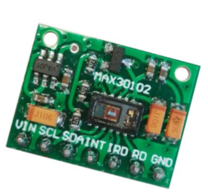
- Max31002 sensor
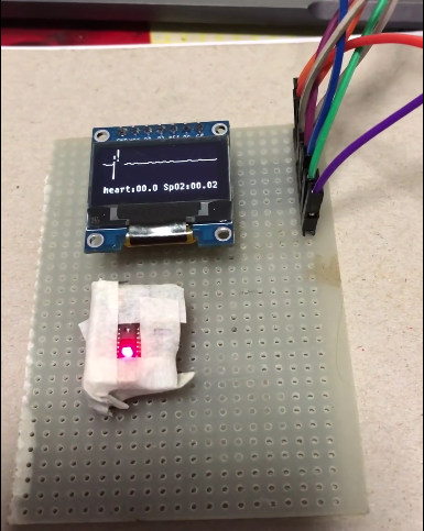
- OLED screen: used to display real-time heart rate waveform
3 realization effect
State when not tested: the heart rate waveform shows a stable straight line, i.e. 0
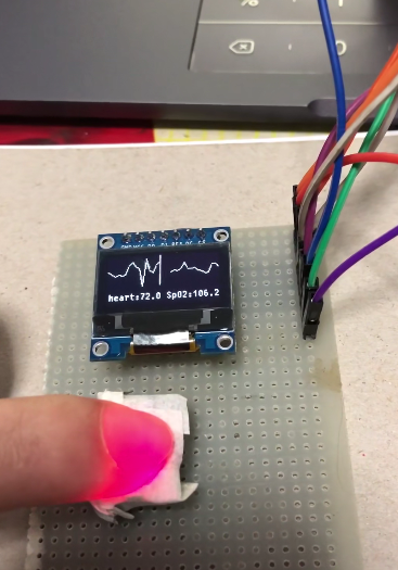
Put your finger on the for heart rate test:
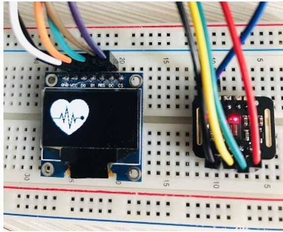
You can also make the image heart-shaped
4 design principle
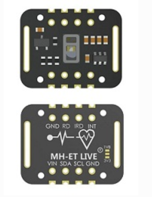
4.1 MAX30102 module
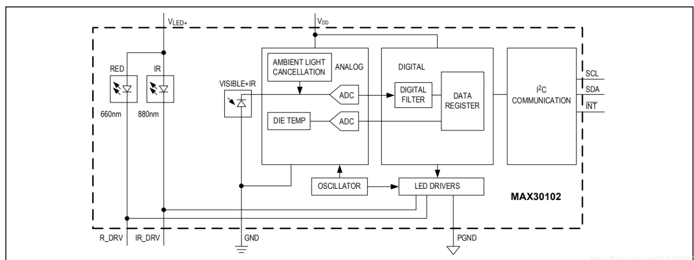
Max31002 is an integrated pulse oximeter and heart rate monitor biosensor module. It integrates a red light LEO and an infrared light LEO, photodetectors, optical devices, and low-noise electronic circuits with ambient light suppression. MAX30102 adopts a 1.8V power supply and an independent 5.0V power supply for internal LEO. It is applied to wearable devices for heart rate and blood oxygen collection and detection, and worn at fingers, earlobes and wrists. The standard I2C compatible communication interface can transmit the collected values to Arduino, STM32 and other MCU for heart rate and blood oxygen calculation. In addition, the chip can also turn off the module through software, and the standby current is close to zero, so that the power supply can always maintain the power supply state.
Chip internal circuit diagram:
4.2 basic principle of heart rate detection
4.2.1 PPG optical capacitance product method
Because the reflection of human skin, bone, muscle and fat to light is a fixed value, while the reflection of capillaries, arteries and veins to light is a fluctuating value because they keep getting larger and smaller with the pulse volume, and this fluctuating value is just consistent with the heart rate, so the photoelectric volume method determines the user's heart rate data through this fluctuating frequency.
At present, the vast majority of smart bracelets / watches on the market use this method to monitor heart rate, and the technical scheme of this method has been relatively mature, so the price is relatively low.
4.2. 2 ECG measurement method
There is also an ECG measurement method, which captures the small electrode changes of people's heart beat every time through the sensor mounted on the intelligent wearable device, and then restores the heart beat frequency through the algorithm. The principle is similar to that of ECG. At present, few intelligent wearable devices adopt this method.
Part 5 implementation code
Heart rate blood sample algorithm:
/** \file algorithm.c ******************************************************
*
* Project: MAXREFDES117#
* Filename: algorithm.cpp
* Description: This module calculates the heart rate/SpO2 level
*
*
* --------------------------------------------------------------------
*
* This code follows the following naming conventions:
*
* char              ch_pmod_value
* char (array)      s_pmod_s_string[16]
* float             f_pmod_value
* int32_t           n_pmod_value
* int32_t (array)   an_pmod_value[16]
* int16_t           w_pmod_value
* int16_t (array)   aw_pmod_value[16]
* uint16_t          uw_pmod_value
* uint16_t (array)  auw_pmod_value[16]
* uint8_t           uch_pmod_value
* uint8_t (array)   auch_pmod_buffer[16]
* uint32_t          un_pmod_value
* int32_t *         pn_pmod_value
*
* ------------------------------------------------------------------------- */
/*******************************************************************************
* Copyright (C) 2016 Maxim Integrated Products, Inc., All Rights Reserved.
*
* Permission is hereby granted, free of charge, to any person obtaining a
* copy of this software and associated documentation files (the "Software"),
* to deal in the Software without restriction, including without limitation
* the rights to use, copy, modify, merge, publish, distribute, sublicense,
* and/or sell copies of the Software, and to permit persons to whom the
* Software is furnished to do so, subject to the following conditions:
*
* The above copyright notice and this permission notice shall be included
* in all copies or substantial portions of the Software.
*
* THE SOFTWARE IS PROVIDED "AS IS", WITHOUT WARRANTY OF ANY KIND, EXPRESS
* OR IMPLIED, INCLUDING BUT NOT LIMITED TO THE WARRANTIES OF
* MERCHANTABILITY, FITNESS FOR A PARTICULAR PURPOSE AND NONINFRINGEMENT.
* IN NO EVENT SHALL MAXIM INTEGRATED BE LIABLE FOR ANY CLAIM, DAMAGES
* OR OTHER LIABILITY, WHETHER IN AN ACTION OF CONTRACT, TORT OR OTHERWISE,
* ARISING FROM, OUT OF OR IN CONNECTION WITH THE SOFTWARE OR THE USE OR
* OTHER DEALINGS IN THE SOFTWARE.
*
* Except as contained in this notice, the name of Maxim Integrated
* Products, Inc. shall not be used except as stated in the Maxim Integrated
* Products, Inc. Branding Policy.
*
* The mere transfer of this software does not imply any licenses
* of trade secrets, proprietary technology, copyrights, patents,
* trademarks, maskwork rights, or any other form of intellectual
* property whatsoever. Maxim Integrated Products, Inc. retains all
* ownership rights.
*******************************************************************************
*/
#include "algorithm.h"

const uint16_t auw_hamm[31]={ 41,    276,    512,    276,     41 }; //Hamm=  long16(512* hamming(5)');
//uch_spo2_table is computed as  -45.060*ratioAverage* ratioAverage + 30.354 *ratioAverage + 94.845 ;
const uint8_t uch_spo2_table[184]={ 95, 95, 95, 96, 96, 96, 97, 97, 97, 97, 97, 98, 98, 98, 98, 98, 99, 99, 99, 99,
                            99, 99, 99, 99, 100, 100, 100, 100, 100, 100, 100, 100, 100, 100, 100, 100, 100, 100, 100, 100,
                            100, 100, 100, 100, 99, 99, 99, 99, 99, 99, 99, 99, 98, 98, 98, 98, 98, 98, 97, 97,
                            97, 97, 96, 96, 96, 96, 95, 95, 95, 94, 94, 94, 93, 93, 93, 92, 92, 92, 91, 91,
                            90, 90, 89, 89, 89, 88, 88, 87, 87, 86, 86, 85, 85, 84, 84, 83, 82, 82, 81, 81,
                            80, 80, 79, 78, 78, 77, 76, 76, 75, 74, 74, 73, 72, 72, 71, 70, 69, 69, 68, 67,
                            66, 66, 65, 64, 63, 62, 62, 61, 60, 59, 58, 57, 56, 56, 55, 54, 53, 52, 51, 50,
                            49, 48, 47, 46, 45, 44, 43, 42, 41, 40, 39, 38, 37, 36, 35, 34, 33, 31, 30, 29,
                            28, 27, 26, 25, 23, 22, 21, 20, 19, 17, 16, 15, 14, 12, 11, 10, 9, 7, 6, 5,
                            3, 2, 1 } ;
static  int32_t an_dx[ BUFFER_SIZE-MA4_SIZE]; // delta
static  int32_t an_x[ BUFFER_SIZE]; //ir
static  int32_t an_y[ BUFFER_SIZE]; //red

void maxim_heart_rate_and_oxygen_saturation(uint32_t *pun_ir_buffer,  int16_t n_ir_buffer_length, uint32_t *pun_red_buffer, int16_t *pn_spo2, int8_t *pch_spo2_valid,
                              int16_t *pn_heart_rate, int8_t  *pch_hr_valid)
/**
* \brief        Calculate the heart rate and SpO2 level
* \par          Details
*               By detecting  peaks of PPG cycle and corresponding AC/DC of red/infra-red signal, the ratio for the SPO2 is computed.
*               Since this algorithm is aiming for Arm M0/M3. formaula for SPO2 did not achieve the accuracy due to register overflow.
*               Thus, accurate SPO2 is precalculated and save longo uch_spo2_table[] per each ratio.
*
* \param[in]    *pun_ir_buffer           - IR sensor data buffer
* \param[in]    n_ir_buffer_length      - IR sensor data buffer length
* \param[in]    *pun_red_buffer          - Red sensor data buffer
* \param[out]    *pn_spo2                - Calculated SpO2 value
* \param[out]    *pch_spo2_valid         - 1 if the calculated SpO2 value is valid
* \param[out]    *pn_heart_rate          - Calculated heart rate value
* \param[out]    *pch_hr_valid           - 1 if the calculated heart rate value is valid
*
* \retval       None
*/
{
    uint32_t un_ir_mean ,un_only_once ;
    int32_t k ,n_i_ratio_count;
    int32_t i, s, m, n_exact_ir_valley_locs_count ,n_middle_idx;
    int32_t n_th1, n_npks,n_c_min;
    int32_t an_ir_valley_locs[15] ;
    int32_t an_exact_ir_valley_locs[15] ;
    int32_t an_dx_peak_locs[15] ;
    int32_t n_peak_interval_sum;

    int32_t n_y_ac, n_x_ac;
    int32_t n_spo2_calc;
    int32_t n_y_dc_max, n_x_dc_max;
    int32_t n_y_dc_max_idx, n_x_dc_max_idx;
    int32_t an_ratio[5],n_ratio_average;
    int32_t n_nume,  n_denom ;
    // remove DC of ir signal
    un_ir_mean =0;
    for (k=0 ; k<n_ir_buffer_length ; k++ ) un_ir_mean += pun_ir_buffer[k] ;
    un_ir_mean =un_ir_mean/n_ir_buffer_length ;
    for (k=0 ; k<n_ir_buffer_length ; k++ )  an_x[k] =  pun_ir_buffer[k] - un_ir_mean ;

    // 4 pt Moving Average
    for(k=0; k< BUFFER_SIZE-MA4_SIZE; k++){
        n_denom= ( an_x[k]+an_x[k+1]+ an_x[k+2]+ an_x[k+3]);
        an_x[k]=  n_denom/(int32_t)4;
    }

    // get difference of smoothed IR signal

    for( k=0; k<BUFFER_SIZE-MA4_SIZE-1;  k++)
        an_dx[k]= (an_x[k+1]- an_x[k]);

    // 2-pt Moving Average to an_dx
    for(k=0; k< BUFFER_SIZE-MA4_SIZE-2; k++){
        an_dx[k] =  ( an_dx[k]+an_dx[k+1])/2 ;
    }

    // hamming window
    // flip wave form so that we can detect valley with peak detector
    for ( i=0 ; i<BUFFER_SIZE-HAMMING_SIZE-MA4_SIZE-2 ;i++){
        s= 0;
        for( k=i; k<i+ HAMMING_SIZE ;k++){
            s -= an_dx[k] *auw_hamm[k-i] ;
                     }
        an_dx[i]= s/ (int32_t)1146; // divide by sum of auw_hamm
    }


    n_th1=0; // threshold calculation
    for ( k=0 ; k<BUFFER_SIZE-HAMMING_SIZE ;k++){
        n_th1 += ((an_dx[k]>0)? an_dx[k] : ((int32_t)0-an_dx[k])) ;
    }
    n_th1= n_th1/ ( BUFFER_SIZE-HAMMING_SIZE);
    // peak location is acutally index for sharpest location of raw signal since we flipped the signal
    maxim_find_peaks( an_dx_peak_locs, &n_npks, an_dx, BUFFER_SIZE-HAMMING_SIZE, n_th1, 8, 5 );//peak_height, peak_distance, max_num_peaks

    n_peak_interval_sum =0;
    if (n_npks>=2){
        for (k=1; k<n_npks; k++)
            n_peak_interval_sum += (an_dx_peak_locs[k]-an_dx_peak_locs[k -1]);
        n_peak_interval_sum=n_peak_interval_sum/(n_npks-1);
        *pn_heart_rate=(int32_t)(6000/n_peak_interval_sum);// beats per minutes
        *pch_hr_valid  = 1;
    }
    else  {
        *pn_heart_rate = -999;
        *pch_hr_valid  = 0;
    }

    for ( k=0 ; k<n_npks ;k++)
        an_ir_valley_locs[k]=an_dx_peak_locs[k]+HAMMING_SIZE/2;


    // raw value : RED(=y) and IR(=X)
    // we need to assess DC and AC value of ir and red PPG.
    for (k=0 ; k<n_ir_buffer_length ; k++ )  {
        an_x[k] =  pun_ir_buffer[k] ;
        an_y[k] =  pun_red_buffer[k] ;
    }

    // find precise min near an_ir_valley_locs
    n_exact_ir_valley_locs_count =0;
    for(k=0 ; k<n_npks ;k++){
        un_only_once =1;
        m=an_ir_valley_locs[k];
        n_c_min= 16777216;//2^24;
        if (m+5 <  BUFFER_SIZE-HAMMING_SIZE  && m-5 >0){
            for(i= m-5;i<m+5; i++)
                if (an_x[i]<n_c_min){
                    if (un_only_once >0){
                       un_only_once =0;
                   }
                   n_c_min= an_x[i] ;
                   an_exact_ir_valley_locs[k]=i;
                }
            if (un_only_once ==0)
                n_exact_ir_valley_locs_count ++ ;
        }
    }
    if (n_exact_ir_valley_locs_count <2 ){
       *pn_spo2 =  -999 ; // do not use SPO2 since signal ratio is out of range
       *pch_spo2_valid  = 0;
       return;
    }
    // 4 pt MA
    for(k=0; k< BUFFER_SIZE-MA4_SIZE; k++){
        an_x[k]=( an_x[k]+an_x[k+1]+ an_x[k+2]+ an_x[k+3])/(int32_t)4;
        an_y[k]=( an_y[k]+an_y[k+1]+ an_y[k+2]+ an_y[k+3])/(int32_t)4;
    }

    //using an_exact_ir_valley_locs , find ir-red DC andir-red AC for SPO2 calibration ratio
    //finding AC/DC maximum of raw ir * red between two valley locations
    n_ratio_average =0;
    n_i_ratio_count =0;

    for(k=0; k< 5; k++) an_ratio[k]=0;
    for (k=0; k< n_exact_ir_valley_locs_count; k++){
        if (an_exact_ir_valley_locs[k] > BUFFER_SIZE ){
            *pn_spo2 =  -999 ; // do not use SPO2 since valley loc is out of range
            *pch_spo2_valid  = 0;
            return;
        }
    }
    // find max between two valley locations
    // and use ratio betwen AC compoent of Ir & Red and DC compoent of Ir & Red for SPO2

    for (k=0; k< n_exact_ir_valley_locs_count-1; k++){
        n_y_dc_max= -16777216 ;
        n_x_dc_max= - 16777216;
        if (an_exact_ir_valley_locs[k+1]-an_exact_ir_valley_locs[k] >10){
            for (i=an_exact_ir_valley_locs[k]; i< an_exact_ir_valley_locs[k+1]; i++){
                if (an_x[i]> n_x_dc_max) {n_x_dc_max =an_x[i];n_x_dc_max_idx =i; }
                if (an_y[i]> n_y_dc_max) {n_y_dc_max =an_y[i];n_y_dc_max_idx=i;}
            }
            n_y_ac= (an_y[an_exact_ir_valley_locs[k+1]] - an_y[an_exact_ir_valley_locs[k] ] )*(n_y_dc_max_idx -an_exact_ir_valley_locs[k]); //red
            n_y_ac=  an_y[an_exact_ir_valley_locs[k]] + n_y_ac/ (an_exact_ir_valley_locs[k+1] - an_exact_ir_valley_locs[k])  ;


            n_y_ac=  an_y[n_y_dc_max_idx] - n_y_ac;    // subracting linear DC compoenents from raw
            n_x_ac= (an_x[an_exact_ir_valley_locs[k+1]] - an_x[an_exact_ir_valley_locs[k] ] )*(n_x_dc_max_idx -an_exact_ir_valley_locs[k]); // ir
            n_x_ac=  an_x[an_exact_ir_valley_locs[k]] + n_x_ac/ (an_exact_ir_valley_locs[k+1] - an_exact_ir_valley_locs[k]);
            n_x_ac=  an_x[n_y_dc_max_idx] - n_x_ac;      // subracting linear DC compoenents from raw
            n_nume=( n_y_ac *n_x_dc_max)>>7 ; //prepare X100 to preserve floating value
            n_denom= ( n_x_ac *n_y_dc_max)>>7;
            if (n_denom>0  && n_i_ratio_count <5 &&  n_nume != 0)
            {
                an_ratio[n_i_ratio_count]= (n_nume*100)/n_denom ; //formular is ( n_y_ac *n_x_dc_max) / ( n_x_ac *n_y_dc_max) ;
                n_i_ratio_count++;
            }
        }
    }

    maxim_sort_ascend(an_ratio, n_i_ratio_count);
    n_middle_idx= n_i_ratio_count/2;

    if (n_middle_idx >1)
        n_ratio_average =( an_ratio[n_middle_idx-1] +an_ratio[n_middle_idx])/2; // use median
    else
        n_ratio_average = an_ratio[n_middle_idx ];

    if( n_ratio_average>2 && n_ratio_average <184){
        n_spo2_calc= uch_spo2_table[n_ratio_average] ;
        *pn_spo2 = n_spo2_calc ;
        *pch_spo2_valid  = 1;//  float_SPO2 =  -45.060*n_ratio_average* n_ratio_average/10000 + 30.354 *n_ratio_average/100 + 94.845 ;  // for comparison with table
    }
    else{
        *pn_spo2 =  -999 ; // do not use SPO2 since signal ratio is out of range
        *pch_spo2_valid  = 0;
    }
}


void maxim_find_peaks(int32_t *pn_locs, int32_t *pn_npks, int32_t *pn_x, int32_t n_size, int32_t n_min_height, int32_t n_min_distance, int32_t n_max_num)
/**
* \brief        Find peaks
* \par          Details
*               Find at most MAX_NUM peaks above MIN_HEIGHT separated by at least MIN_DISTANCE
*
* \retval       None
*/
{
    maxim_peaks_above_min_height( pn_locs, pn_npks, pn_x, n_size, n_min_height );
    maxim_remove_close_peaks( pn_locs, pn_npks, pn_x, n_min_distance );
    *pn_npks = min( *pn_npks, n_max_num );
}

void maxim_peaks_above_min_height(int32_t *pn_locs, int32_t *pn_npks, int32_t  *pn_x, int32_t n_size, int32_t n_min_height)
/**
* \brief        Find peaks above n_min_height
* \par          Details
*               Find all peaks above MIN_HEIGHT
*
* \retval       None
*/
{
    int32_t i = 1, n_width;
    *pn_npks = 0;

    while (i < n_size-1){
        if (pn_x[i] > n_min_height && pn_x[i] > pn_x[i-1]){            // find left edge of potential peaks
            n_width = 1;
            while (i+n_width < n_size && pn_x[i] == pn_x[i+n_width])    // find flat peaks
                n_width++;
            if (pn_x[i] > pn_x[i+n_width] && (*pn_npks) < 15 ){                            // find right edge of peaks
                pn_locs[(*pn_npks)++] = i;
                // for flat peaks, peak location is left edge
                i += n_width+1;
            }
            else
                i += n_width;
        }
        else
            i++;
    }
}


void maxim_remove_close_peaks(int32_t *pn_locs, int32_t *pn_npks, int32_t *pn_x, int32_t n_min_distance)
/**
* \brief        Remove peaks
* \par          Details
*               Remove peaks separated by less than MIN_DISTANCE
*
* \retval       None
*/
{

    int32_t i, j, n_old_npks, n_dist;

    /* Order peaks from large to small */
    maxim_sort_indices_descend( pn_x, pn_locs, *pn_npks );

    for ( i = -1; i < *pn_npks; i++ ){
        n_old_npks = *pn_npks;
        *pn_npks = i+1;
        for ( j = i+1; j < n_old_npks; j++ ){
            n_dist =  pn_locs[j] - ( i == -1 ? -1 : pn_locs[i] ); // lag-zero peak of autocorr is at index -1
            if ( n_dist > n_min_distance || n_dist < -n_min_distance )
                pn_locs[(*pn_npks)++] = pn_locs[j];
        }
    }

    // Resort indices longo ascending order
    maxim_sort_ascend( pn_locs, *pn_npks );
}

void maxim_sort_ascend(int32_t *pn_x,int32_t n_size)
/**
* \brief        Sort array
* \par          Details
*               Sort array in ascending order (insertion sort algorithm)
*
* \retval       None
*/
{
    int32_t i, j, n_temp;
    for (i = 1; i < n_size; i++) {
        n_temp = pn_x[i];
        for (j = i; j > 0 && n_temp < pn_x[j-1]; j--)
            pn_x[j] = pn_x[j-1];
        pn_x[j] = n_temp;
    }
}

void maxim_sort_indices_descend(int32_t *pn_x, int32_t *pn_indx, int32_t n_size)
/**
* \brief        Sort indices
* \par          Details
*               Sort indices according to descending order (insertion sort algorithm)
*
* \retval       None
*/
{
    int32_t i, j, n_temp;
    for (i = 1; i < n_size; i++) {
        n_temp = pn_indx[i];
        for (j = i; j > 0 && pn_x[n_temp] > pn_x[pn_indx[j-1]]; j--)
            pn_indx[j] = pn_indx[j-1];
        pn_indx[j] = n_temp;
    }
}
6 finally
Technical solutions
 Design help:<Q>746876041
Complete set of single chip microcomputer projects:
https://blog.csdn.net/huawei123444/article/details/119822845