This article can be regarded as an end to the smart car. Later, we'll see if we can share other things. It's a little lazy. At first, we thought about whether we can be Zhou Geng, and finally it became Nian Geng. hhh, I don't know whether the things mentioned before have helped you.
The electromagnetic loop is divided into several parts. First of all, I want to introduce an idea to you, that is, the camera can patch the wire. Why can't the electromagnetic patch the wire? We can achieve the need of entering the loop by compensating the value of the difference ratio and.
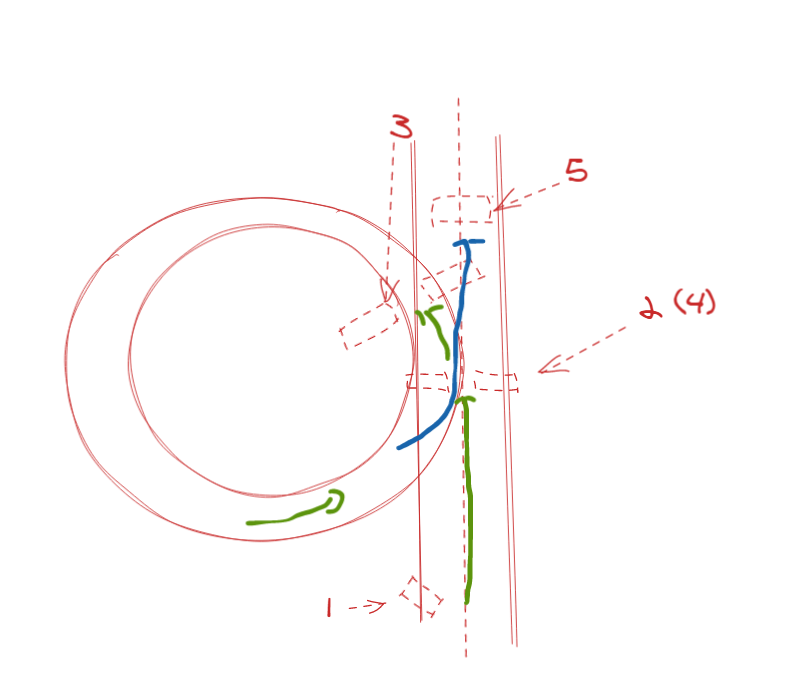
The electromagnetic ring is divided into the following parts: 1 Detection of Roundabout (pre roundabout), 2 Determine the roundabout, 3 Ring in, 4 Test the roundabout again, 5 flip out
Take the left ring island as an example:
Explain according to the code:
link
https://gitee.com/HSqian/zhinengchexiaosaisanlun.git
- Difference ratio and result (in adc_RTT file)
if (Compensate_flag == 1)
		{
			dif_and_add = ADC_Compensate + 100 * err_get(Horizontal_L, Chevron_inL, Chevron_inR, Horizontal_R, Turn_A, Turn_B);
		}
else
		{
			//Moving mean filtering
			cur_tem = 100 * err_get(Horizontal_L, Chevron_inL, Chevron_inR, Horizontal_R, Turn_A, Turn_B); //Deviation degree of difference ratio and (difference)
			dif_and_add = 0.5 * cur_tem + 0.5 * last_nine;
			last_nine = moving_filter(cur_tem);
		}
This part is the result of calculating the difference ratio sum. If compensation is required, a compensation value will be given, otherwise first-order filtering and window filtering will be carried out.
The essence of the comparison here is the value of Compensate. All incoming and outgoing loops are operated through compensation.
Turn_A is used to control the transverse inductance, Turn_B is used to control the internal eight character inductance
Turn_A is used to control the transverse inductance, Turn_B is used to control the internal eight character inductance
Turn_A is used to control the transverse inductance, Turn_B is used to control the internal eight character inductance
Turn_A is used to control the transverse inductance, Turn_B is used to control the internal eight character inductance
Turn_A is used to control the transverse inductance, Turn_B is used to control the internal eight character inductance
Turn_A is used to control the transverse inductance, Turn_B is used to control the internal eight character inductance
To avoid not understanding, repeat several times
The horizontal inductance is mainly used for straight line, so Turn_A large; The inner eight is used for entering the ring, so Turn_B big
The following (X in the figure) are the positions judged by if!!!
2. Pre Roundabout (1 in the figure)
 switch (ring_state)
    {
    case ring_noring:
    {
        /*
        	@Obviously, chevron_ outR/Chevron_ One of the outls is a necessary condition for judging the roundabout
        	@The main difference is the cross and the misjudgment caused by the skew of the car body
        	@
        */

           if (Chevron_outL > 15) //For the right side roundabout, it is necessary to ensure that the horizontal value on the right side is greater than one value, so as to ensure that the larger value is not caused by the skew of the vehicle
        {
            ring_state = ring_rightring;
            right_ring_mode = 1; //This flag bit is used in real_ It is used in the out phase to judge whether the left side is out of the loop or the right side is out of the loop

            flag_buzzer = 1;
            flag.ring = 1;
            flag.fork = 0;
            flag.ramp = 0; //When entering the roundabout, mark all other flag bits as 0

            //------------------Change the fork size here
            Ring_Size = Midring;
#if TIMES / / multiple roundabouts?
            if (right_time == 0)
            {
                Ring_Size = Midring;
            }
            else if (right_time == 1)
            {
                Ring_Size = Midring;
            }

#endif

        } //-------First sound

        //If (chevron_outl > = 90 & & horizontal_l > 20 & & chevron_inl > 15 & & chevron_inr > 10 & & ((30 > chevron_outr) & & (chevron_outr > 15)) / / force creation condition
        else if (Chevron_outL >= 90 && Horizontal_L > 20 && Chevron_inL > 15 && Chevron_inR > 10 && zebra_flag == 0)//Zebra crossing flag bit 0 rookie judgment
        {
            ring_state = ring_leftring;
            left_ring_mode = 1; //This flag bit is used in real_ It is used in the out phase to judge whether the left side is out of the loop or the right side is out of the loop

            flag_buzzer = 1;
            flag.ring = 1;
            flag.fork = 0;
            flag.ramp = 0; //When entering the roundabout, mark all other flag bits as 0

            //------------------Change the fork size here
            Ring_Size = Midring;
#if TIMES / / multiple roundabouts?
            if (left_time == 0)
            {
                Ring_Size = Midring;
            }
            else if (left_time == 1)
            {
                Ring_Size = Midring;
            }
#endif
        }
    };
    break; //-------First sound
This part is used to judge whether it is a left ring island or a right ring Island, and modify the size of the ring Island (the compensation and compensation time of different ring islands need to be adjusted). It is only for judgment and given Ring_Size (to be used later).
- Insert the left ring (2 places in the figure)
   case ring_leftring:
    {
        Turn_B = 0.8;
        Turn_A = 0.2;
        if (Compensate_flag == 0)
        {
            Ringin_Size_Chose(Ring_Size);
        }

        if (Ring_Delay == 0) //Modify the value of Ring_Delay according to the guide length
        {
            ring_state = ring_prein;
            flag_buzzer = 1;
#if TIMES / / multiple roundabouts?
            left_time += 1;
#endif
        }
    };
Turn_B = 0.8,Turn_A = 0.2; Modify the difference ratio and the weight of inductance in the difference, and execute ringin_ Size_ The choose() function.
Next, let's talk about Ringin_Size_Chose()
void Ringin_Size_Chose(int Size)
{
    Compensate_flag = 1;

    switch (Size)
    {
    case Bigring:
    {
        if (right_ring_mode == 1)
        {
            Ring_Delay = 130;
            ADC_Compensate = -30; //The left side should be corrected and the right side should be negative
        }
        else if (left_ring_mode == 1)
        {
            Ring_Delay = 130;
            ADC_Compensate = 30; //The left side should be corrected and the right side should be negative
        }
    }
    break;

    case Midring:
    {
        if (right_ring_mode == 1)
        {
            Ring_Delay = 100;
            ADC_Compensate = -30; //The left side should be corrected and the right side should be negative
        }
        else if (left_ring_mode == 1)
        {
            Ring_Delay = 200;
            ADC_Compensate = 30; //The left side should be corrected and the right side should be negative
        }
    }
    break;

    case Smallring:
    {
        if (right_ring_mode == 1)
        {
            Ring_Delay = 80;
            ADC_Compensate = -30; //The left side should be corrected and the right side should be negative
        }
        else if (left_ring_mode == 1)
        {
            Ring_Delay = 80;
            ADC_Compensate = 30; //The left side should be corrected and the right side should be negative
        }
    }
    break;

    default:
        break;
    }
}
First, Compensate_flag = 1, which means that the value of the difference ratio sum in 1 needs to be compensated, and the supplementary size is through Ring_Size and left and right rings to determine, Ring_Delay is the compensation time. This value varies with different vehicle speeds and needs to be modified. It is equivalent to the time when the vehicle is forced to push around the island.
- Pre insert ring (3 places in the figure)
   case ring_prein:
    {
        Compensate_flag = 0;
        if (Horizontal_R + Horizontal_R < 120)
        {
            ring_state = ring_ringin;
            flag_buzzer = 1;
            Ring_Delay = 50;
        }
    };
    break; //-------Third sound
Set the compensation to 0 and stop the compensation
- Ring in (3 places in the figure) (yes, it is almost in the same position as the pre ring)
   case ring_ringin:
    {
        Target_Speed = Gear[0];
        Turn_A = 0.8;
        Turn_B = 0.2;
        if (Chevron_outL > 90 || Chevron_outR > 90 || Ring_Delay == 0)
        {
            ring_state = ring_out;
            flag_buzzer = 1;
            Ring_Delay = 50;
        }
    };
    break; //-------Fourth sound
Modify the weight and change the speed in the loop
- Ring out (4 places in the figure)
   case ring_out:
    {
        Target_Speed = Gear[0];
        Turn_A = 0.8;
        Turn_B = 0.2;
        if ((GFP_abs(Horizontal_R - Horizontal_L) < 10 &&
             (Horizontal_R < 90 || Horizontal_L < 90)) ||
            Ring_Delay == 0)
        {
            ring_state = ring_realout;
            flag_buzzer = 1;
            Ring_Delay = 50;
        }
    }
    break;
Give the weight again to get out of the loop
- Bird eating out ring (5 places in the figure)
   case ring_realout:
    {
        Ringout_Size_Chose(Ring_Size);

        if (Horizontal_L + Horizontal_R < 100 || Ring_Delay == 0)
        {
            Turn_A = 1;
            flag_buzzer = 1;
            ring_state = ring_noring;
            Compensate_flag = 0;

            flag.ring = 0; //Set the roundabout flag position to 0
            left_ring_mode = 0;
            right_ring_mode = 0;
        }
    };
    break;
Ringout_ Size_ Choose (ring_size) is similar to the previous one, except that the compensation value is negative.
You'll find a lot of rings in it_ One purpose of delay is to prevent continuous judgment of flag bits and interval (anti misjudgment), and the other purpose is to delay entry.
That's all. See you in the Jianghu.