Preparatory knowledge
When the MCU of ARM Cortex series is reset and powered on, it will obtain the vector table from the memory address of 0x00000000. The user software can also modify the storage address of the vector table by writing to the VTOR register. This value is equivalent to flash_ The offset of the base address, so that the program can obtain the vector table from different storage locations. The VTOR register stores the offset value of the base address of the vector table relative to the 0x000000 address.
The complete vector table is similar to the following figure:
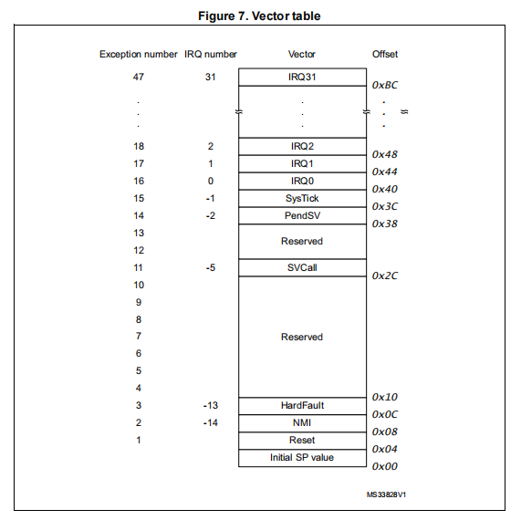
Firstly, the address of 0x00 stores the stack pointer, that is, the MCU core is used to set the initial value of MSP register, while the address of 0x04 stores the starting address of all exception vector values, that is, the MCU core is used to set the initial value of PC register. These two values are in stm32 chip and can be configured in MDK - > target. Note: it is necessary for MSP register to be set first. This is because when MCU is reset, it is likely to generate NMI and HardFault exceptions in a very short time. Before exception handling, pressing the processor on the stack requires the operation of line stack storage.
STM32 burn configuration
When writing stm32 programs using MDK, our settings are generally similar to the following figure. We configure the starting address of the program and the starting address of the stack pointer (RAM memory). Generally, this configuration is based on the files in our Device configuration. This address of each model is not necessarily the same, so the model should be selected correctly. When burning later, It won't burn mistakes.
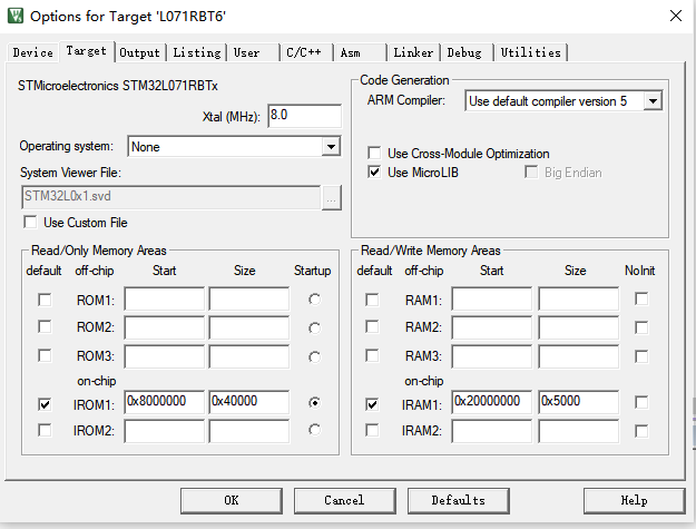
This configuration will eventually be output to the sct file, which will ensure that the first address of the binary file burned to MCU is the value of the stack pointer and the second address is the starting address of the exception vector.
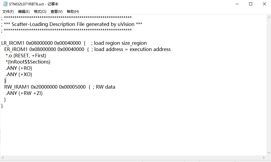
STM32 startup settings
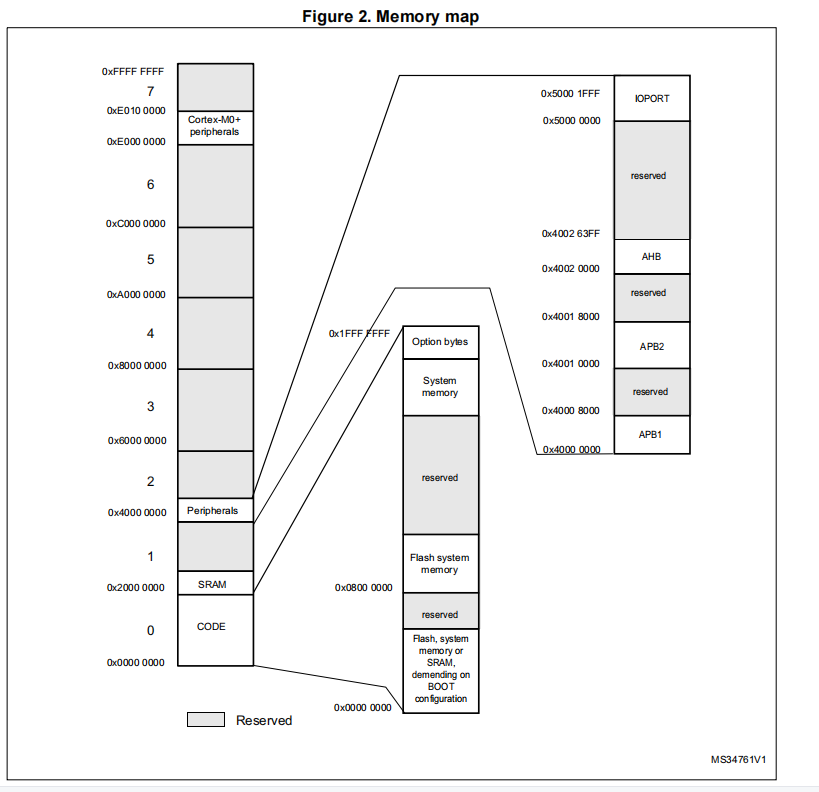
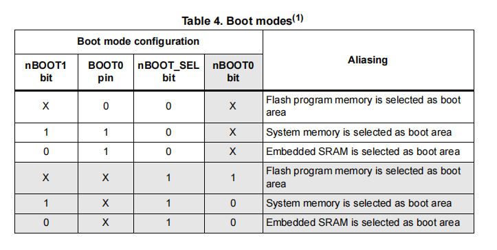
Since the arm specifies that after power on, the MCU takes the value and executes from the address of 0x0000000, why does stm32 configure the location of RO memory from the address of 0x08000000 when burning? This problem is because ST company has designed three startup modes through address mapping. As shown in the figure below:
- When start from flash is set, stm32 mcu will map the address 0x0000000 to 0x08000000. When mcu starts from 0x00000000, the read value is the same as that of 0x08000000.
- When start from SRAM is set, stm32 mcu will map 0x20000000 address to 0x08000000.
- When start from system memory is set, the address of system memory (0x1FF00000) will be mapped to 0x00000000. In fact, this part of the memory stores the bootloader written by ST official when producing the chip, which is convenient for users to download from ISP.
- stm32 memory map.
- stm32 selects the Boot memory area by configuring the Boot pin in the following manner.
STM32 startup code
This part mainly refers to the assembly code officially provided by st,
- First define the space size of stack and heap.
- Open up memory space to store the address of stack pointer and the address of all exception vectors, that is, create vector table. This part of the data will be stored in the specified flash according to the above configuration. The first address of the vector table is used to initialize the stack pointer MSP, and the second address of the vector table is used to initialize the initial value of the PC register,
- The program will jump to reset first_ Handler vector.
- Then jump to the SystemInit configuration function.
- Finally, jump to the database in C__ Main function passed__ user_initial_stackheap reads the stack pointer to initialize the stack, and finally jumps to the main function to execute the main program.
As shown below.
Stack_Size      EQU     0x00000400

                AREA    STACK, NOINIT, READWRITE, ALIGN=3
Stack_Mem       SPACE   Stack_Size
__initial_sp


; <h> Heap Configuration
;   <o>  Heap Size (in Bytes) <0x0-0xFFFFFFFF:8>
; </h>

Heap_Size       EQU     0x00000200

                AREA    HEAP, NOINIT, READWRITE, ALIGN=3
__heap_base
Heap_Mem        SPACE   Heap_Size
__heap_limit

                PRESERVE8
                THUMB


; Vector Table Mapped to Address 0 at Reset
                AREA    RESET, DATA, READONLY
                EXPORT  __Vectors
                EXPORT  __Vectors_End
                EXPORT  __Vectors_Size

__Vectors       DCD     __initial_sp              ; Top of Stack
                DCD     Reset_Handler             ; Reset Handler
                DCD     NMI_Handler               ; NMI Handler
                DCD     HardFault_Handler         ; Hard Fault Handler
                DCD     0                         ; Reserved
                DCD     0                         ; Reserved
                DCD     0                         ; Reserved
                DCD     0                         ; Reserved
                DCD     0                         ; Reserved
                DCD     0                         ; Reserved
                DCD     0                         ; Reserved
                DCD     SVC_Handler               ; SVCall Handler
                DCD     0                         ; Reserved
                DCD     0                         ; Reserved
                DCD     PendSV_Handler            ; PendSV Handler
                DCD     SysTick_Handler           ; SysTick Handler

                ; External Interrupts
                DCD     WWDG_IRQHandler                ; Window Watchdog
                DCD     PVD_IRQHandler                 ; PVD through EXTI Line detect
                DCD     RTC_IRQHandler                 ; RTC through EXTI Line
                DCD     FLASH_IRQHandler               ; FLASH
                DCD     RCC_IRQHandler                 ; RCC
                DCD     EXTI0_1_IRQHandler             ; EXTI Line 0 and 1
                DCD     EXTI2_3_IRQHandler             ; EXTI Line 2 and 3
                DCD     EXTI4_15_IRQHandler            ; EXTI Line 4 to 15
                DCD     0                              ; Reserved
                DCD     DMA1_Channel1_IRQHandler       ; DMA1 Channel 1
                DCD     DMA1_Channel2_3_IRQHandler     ; DMA1 Channel 2 and Channel 3
                DCD     DMA1_Channel4_5_6_7_IRQHandler ; DMA1 Channel 4, Channel 5, Channel 6 and Channel 7
                DCD     ADC1_COMP_IRQHandler           ; ADC1, COMP1 and COMP2
                DCD     LPTIM1_IRQHandler              ; LPTIM1
                DCD     USART4_5_IRQHandler            ; USART4 and USART5
                DCD     TIM2_IRQHandler                ; TIM2
                DCD     TIM3_IRQHandler                ; TIM3
                DCD     TIM6_IRQHandler                ; TIM6
                DCD     TIM7_IRQHandler                ; TIM7
                DCD     0                              ; Reserved
                DCD     TIM21_IRQHandler               ; TIM21
                DCD     I2C3_IRQHandler                ; I2C3
                DCD     TIM22_IRQHandler               ; TIM22
                DCD     I2C1_IRQHandler                ; I2C1
                DCD     I2C2_IRQHandler                ; I2C2
                DCD     SPI1_IRQHandler                ; SPI1
                DCD     SPI2_IRQHandler                ; SPI2
                DCD     USART1_IRQHandler              ; USART1
                DCD     USART2_IRQHandler              ; USART2
                DCD     LPUART1_IRQHandler             ; LPUART1
                DCD     0                              ; Reserved
                DCD     0                              ; Reserved

__Vectors_End

__Vectors_Size  EQU  __Vectors_End - __Vectors

                AREA    |.text|, CODE, READONLY

; Reset handler routine
Reset_Handler    PROC
                 EXPORT  Reset_Handler                 [WEAK]
        IMPORT  __main
        IMPORT  SystemInit
                 LDR     R0, =SystemInit
                 BLX     R0
                 LDR     R0, =__main
                 BX      R0
                 ENDP

; Dummy Exception Handlers (infinite loops which can be modified)

NMI_Handler     PROC
                EXPORT  NMI_Handler                    [WEAK]
                B       .
                ENDP
HardFault_Handler\
                PROC
                EXPORT  HardFault_Handler              [WEAK]
                B       .
                ENDP
SVC_Handler     PROC
                EXPORT  SVC_Handler                    [WEAK]
                B       .
                ENDP
PendSV_Handler  PROC
                EXPORT  PendSV_Handler                 [WEAK]
                B       .
                ENDP
SysTick_Handler PROC
                EXPORT  SysTick_Handler                [WEAK]
                B       .
                ENDP

Default_Handler PROC

                EXPORT  WWDG_IRQHandler                [WEAK]
                EXPORT  PVD_IRQHandler                 [WEAK]
                EXPORT  RTC_IRQHandler                 [WEAK]
                EXPORT  FLASH_IRQHandler               [WEAK]
                EXPORT  RCC_IRQHandler                 [WEAK]
                EXPORT  EXTI0_1_IRQHandler             [WEAK]
                EXPORT  EXTI2_3_IRQHandler             [WEAK]
                EXPORT  EXTI4_15_IRQHandler            [WEAK]
                EXPORT  DMA1_Channel1_IRQHandler       [WEAK]
                EXPORT  DMA1_Channel2_3_IRQHandler     [WEAK]
                EXPORT  DMA1_Channel4_5_6_7_IRQHandler [WEAK]
                EXPORT  ADC1_COMP_IRQHandler           [WEAK]
                EXPORT  LPTIM1_IRQHandler              [WEAK]
                EXPORT  USART4_5_IRQHandler            [WEAK]
                EXPORT  TIM2_IRQHandler                [WEAK]
                EXPORT  TIM3_IRQHandler                [WEAK]
                EXPORT  TIM6_IRQHandler                [WEAK]
                EXPORT  TIM7_IRQHandler                [WEAK]
                EXPORT  TIM21_IRQHandler               [WEAK]
                EXPORT  TIM22_IRQHandler               [WEAK]
                EXPORT  I2C1_IRQHandler                [WEAK]
                EXPORT  I2C2_IRQHandler                [WEAK]
                EXPORT  I2C3_IRQHandler                [WEAK]
                EXPORT  SPI1_IRQHandler                [WEAK]
                EXPORT  SPI2_IRQHandler                [WEAK]
                EXPORT  USART1_IRQHandler              [WEAK]
                EXPORT  USART2_IRQHandler              [WEAK]
                EXPORT  LPUART1_IRQHandler             [WEAK]

WWDG_IRQHandler
PVD_IRQHandler
RTC_IRQHandler
FLASH_IRQHandler
RCC_IRQHandler
EXTI0_1_IRQHandler
EXTI2_3_IRQHandler
EXTI4_15_IRQHandler
DMA1_Channel1_IRQHandler
DMA1_Channel2_3_IRQHandler
DMA1_Channel4_5_6_7_IRQHandler
ADC1_COMP_IRQHandler
LPTIM1_IRQHandler
USART4_5_IRQHandler
TIM2_IRQHandler
TIM3_IRQHandler
TIM6_IRQHandler
TIM7_IRQHandler
TIM21_IRQHandler
TIM22_IRQHandler
I2C1_IRQHandler
I2C2_IRQHandler
I2C3_IRQHandler
SPI1_IRQHandler
SPI2_IRQHandler
USART1_IRQHandler
USART2_IRQHandler
LPUART1_IRQHandler

                B       .

                ENDP

                ALIGN

;*******************************************************************************
; User Stack and Heap initialization
;*******************************************************************************
                 IF      :DEF:__MICROLIB

                 EXPORT  __initial_sp
                 EXPORT  __heap_base
                 EXPORT  __heap_limit

                 ELSE

                 IMPORT  __use_two_region_memory
                 EXPORT  __user_initial_stackheap

__user_initial_stackheap

                 LDR     R0, =  Heap_Mem
                 LDR     R1, =(Stack_Mem + Stack_Size)
                 LDR     R2, = (Heap_Mem +  Heap_Size)
                 LDR     R3, = Stack_Mem
                 BX      LR

                 ALIGN

                 ENDIF

                 END

;************************ (C) COPYRIGHT STMicroelectronics *****END OF FILE*****