one EXTI (external interrupt) brief introduction
2. Introduction to 4 * 4 matrix keyboard
.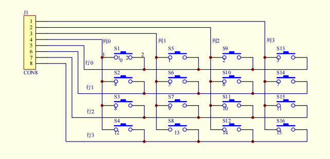
The line reversal method detects which key is pressed:
For example, first, we output the low level to the row and set the pull-up input to the column. When a key is pressed, the potential of the column is pulled down. At this time, we can know that the potential of the column is pulled down by reading the level state of the input pin of the column. When we detect that the potential of the column is pulled down, we let the column output the high level and set the pull-down input mode to the row, Similarly, it can detect which line of potential is pulled up. Of course, there are other key detection methods. Only one of them is introduced here.
3.EXTI configuration steps (based on firmware library development)
void NVIC_Config(void)
{
	NVIC_InitTypeDef   NVIC_InitStruct;                        //NVIC configuration structure
	NVIC_PriorityGroupConfig(NVIC_PriorityGroup_2);             //Configure as group 2

	NVIC_InitStruct.NVIC_IRQChannel = EXTI9_5_IRQn;            //Select break line
	NVIC_InitStruct.NVIC_IRQChannelPreemptionPriority = 0;      //Preemption priority is 0
	NVIC_InitStruct.NVIC_IRQChannelSubPriority = 1;             //The sub priority is 1
	NVIC_InitStruct.NVIC_IRQChannelCmd = ENABLE;               //Enable NVIC
    NVIC_Init(&NVIC_InitStruct);

	NVIC_InitStruct.NVIC_IRQChannel = EXTI2_IRQn;              //Select break line
	NVIC_InitStruct.NVIC_IRQChannelSubPriority = 0;             //The child priority is 0
	NVIC_Init(&NVIC_InitStruct);

	NVIC_InitStruct.NVIC_IRQChannel = EXTI0_IRQn;              //Select break line
	NVIC_InitStruct.NVIC_IRQChannelSubPriority = 1;             //The sub priority is 2
	NVIC_Init(&NVIC_InitStruct);

}

void EXTI_KEY_Init(void)
{
		EXTI_InitTypeDef  EXTI_InitStruct;
		NVIC_Config();
        KEY1_Init();
		RCC_APB2PeriphClockCmd(RCC_APB2Periph_AFIO,ENABLE);
//Enable APB2 clock. Note: external interrupt needs to turn on AFIO clock

        //Initialize column 3 interrupt
	    GPIO_EXTILineConfig(GPIO_PortSourceGPIOB, GPIO_PinSource2);   //Select external interrupt source
	    EXTI_InitStruct.EXTI_Line    = EXTI_Line2;
        EXTI_InitStruct.EXTI_Mode    = EXTI_Mode_Interrupt;       //Configure as interrupt
        EXTI_InitStruct.EXTI_Trigger = EXTI_Trigger_Falling;       //Configured as falling edge trigger
        EXTI_InitStruct.EXTI_LineCmd = ENABLE;
	    EXTI_Init(&EXTI_InitStruct);


		//Initialize column 4 interrupt
	    GPIO_EXTILineConfig(GPIO_PortSourceGPIOB, GPIO_PinSource0);   //Select external interrupt source
	    EXTI_InitStruct.EXTI_Line    = EXTI_Line0;
		EXTI_Init(&EXTI_InitStruct);                                  //Initialization function


		//Initialize column 2 interrupt
	    GPIO_EXTILineConfig(GPIO_PortSourceGPIOB, GPIO_PinSource5);   //Select external interrupt source
	    EXTI_InitStruct.EXTI_Line    = EXTI_Line5;
		EXTI_Init(&EXTI_InitStruct);                              //Initialization function


		//Initialize column 1 interrupt
	    GPIO_EXTILineConfig(GPIO_PortSourceGPIOB, GPIO_PinSource6);   //Select external interrupt source
	    EXTI_InitStruct.EXTI_Line    = EXTI_Line6;
		EXTI_Init(&EXTI_InitStruct);                              //Initialization function


}
(3) Write EXTI interrupt service function
void EXTI2_IRQHandler(void)
{
        if(EXTI_GetITStatus(EXTI_Line2) != RESET)           //Detection interrupt flag bit
		{
			    KEY2_Init();
			    //Read the status of line 4
			       if(Column1==1)
					{
						while(Column1)
						   KeyValue=3;

					}
					if(Column2)
					{

						while(Column2)
						   KeyValue=7;

					}
					if(Column3)
					{

						while(Column3)
					    	KeyValue=11;

					}
					if(Column4)
					{

						while(Column4==1)
						  KeyValue=15;

					}

			EXTI_ClearITPendingBit(EXTI_Line2);                         //Clear flag bit
			KEY1_Init(); //Reset GPIO and wait for the next interrupt
		}

}
(4)exti_key16.h file
#ifndef __STM32F10X_EXTI_KEY16_H__
#define __STM32F10X_EXTI_KEY16_H__


#include "stm32f10x.h"
#include "delay.h"
#include "sys.h"
#include "usart.h"

#define GPIO_CLK 	            RCC_APB2Periph_GPIOB|RCC_APB2Periph_GPIOC

#define Column_GPIO_PORT    	GPIOC
#define Column_GPIO_PIN		    GPIO_Pin_0| GPIO_Pin_1 |GPIO_Pin_2 |GPIO_Pin_3

#define LINE_GPIO_PORT    	    GPIOB
#define LINE_GPIO_PIN		    GPIO_Pin_2 |GPIO_Pin_0 |GPIO_Pin_5 |GPIO_Pin_6

#define Column1       PCin(3) //R4
#define Column2       PCin(2) //R3
#define Column3       PCin(0) //R2
#define Column4       PCin(1) //R1
#define Line1         PBin(6) //C4
#define Line2         PBin(5) //C3
#define Line3         PBin(2) //C2
#define Line4         PBin(0) //C1

void EXTI_KEY_Init(void);


#endif
Finally, this is my first time to write CSDN. There are many deficiencies. Welcome to point out, communicate and learn from each other. Thank you!