1, SPI introduction
SPI is the abbreviation of English Serial Peripheral interface. As the name suggests, it is the Serial Peripheral interface. It was first defined by Motorola on its MC68HCXX series processors. SPI interface is mainly used between EEPROM, FLASH, real-time clock, AD converter, digital signal processor and digital signal decoder. SPI is a high-speed, full duplex and synchronous communication bus, and only occupies four wires on the pins of the chip, which saves the pins of the chip, saves space and provides convenience for the layout of PCB. It is precisely because of this simple and easy-to-use characteristic that more and more chips have integrated this communication protocol.
For more information SPI details
2, 0.96inch SPI OLED introduction
- Picture display
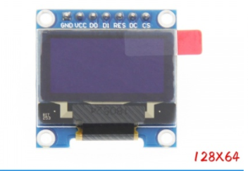
| Serial number | Module pin | Pin description |
|---|---|---|
| 1 | GND | Power ground |
| 2 | OLED | Positive power supply (3.3V~5V) |
| 3 | D0 | SPI and IIC bus clock signals |
| 4 | D1 | OLED SPI and IIC bus data signals |
| 5 | RES | OLED reset signal, low level reset (when IIC bus is selected, this pin needs to be connected to high level (VCC can be connected)) |
| 6 | DC | OLED command / data input selection signal, high level: data, low level: command selection (when 3-wire SPI bus is selected, this pin does not need to be used (it can not be connected); when IIC bus is selected, this pin needs to be grounded) |
| 7 | CS | OLED chip selection signal, low level enable (when IIC bus is selected, this pin needs to be grounded) |
More information 0.96inch SPI OLED Module
3, Experimental contents and results
1. Task requirements
-
Display your student number and name;
-
Display the temperature and humidity of AHT20;
-
Slide up and down or left and right to display long characters, such as "Hello, welcome to the Internet of things 205 training room of Chongqing Jiaotong University!" or a lyrics or poem (it is best to use the hardware screen brushing mode).
2. Preparation
- SPI_PLED module demo program download
- Extract link Chinese dot matrix font library and display tool program
Extraction code: 0614
3. The demonstration is as follows:
When you download the above demo program and open it with keil, you can write the following code in main.c
- Display name and student number first
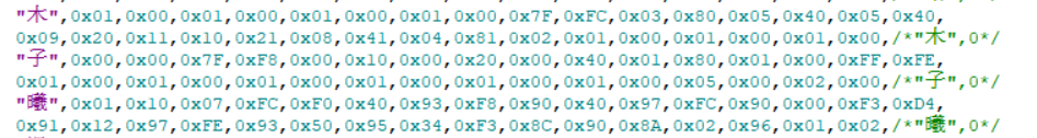
To display Chinese characters, you need to use the above tools to extract the corresponding font, and the tutorial is also included
Add to oledfont.h as follows
void TEST_MainPage1()
{

	  GUI_ShowCHinese(30,0,16,"Mu Zixi",1);//Chinese name
	  GUI_ShowString(5,15,"631907060517",16,1);//Student number
	  Delay_1ms(1000);
}
int main(void)
{
	delay_init();	    	       //Delay function initialization
	OLED_Init();			         //Initialize OLED
	OLED_Clear(0);             //Clear screen (all black)

	/***********************************************************************************/
	/**///①Just after power on, it takes time for the internal readiness of the product chip. The delay is 100~500ms, 500ms is recommended
	/***********************************************************************************/
/***********************************************************************************/
	/**///②Power on and send 0x71 for the first time to read the status word and judge whether the status word is 0x18. If it is not 0x18, initialize the register
	/***********************************************************************************/

   OLED_WR_Byte(0x2E,OLED_CMD); //Turn off scrolling

	OLED_WR_Byte(0x26,OLED_CMD); //Scroll horizontally left or right 26 / 27

	OLED_WR_Byte(0x00,OLED_CMD); //virtual byte

	OLED_WR_Byte(0x00,OLED_CMD); //Start page 0

	OLED_WR_Byte(0x07,OLED_CMD); //Rolling interval

	OLED_WR_Byte(0x01,OLED_CMD); //Termination page 2

	OLED_WR_Byte(0x00,OLED_CMD); //virtual byte

	OLED_WR_Byte(0xFF,OLED_CMD); //virtual byte
	while(1)
	{
		TEST_MainPage1();         //Interface display
		OLED_WR_Byte(0x2F,OLED_CMD); //Turn on scrolling
	    Delay_1ms(2000);

	}
}
- effect
- Display the temperature and humidity data on the screen
AHT20 temperature and humidity data collection based on I2C protocol refers to the data written between me Data acquisition of AHT20 temperature and humidity sensor based on I2C protocol
main.c code:
#include "delay.h"
#include "sys.h"
#include "oled.h"
#include "gui.h"
#include "test.h"
#include "AHT20-21_DEMO_V1_3.h"
void TEST_MainPage1(int c1,int t1)
{

	GUI_ShowCHinese(30,0,16,"Mu Zixi",1);//Chinese name
	GUI_ShowString(5,15,"631907060517",16,1);//Digital detail
    GUI_ShowCHinese(5,30,16,"humidity",1);
    GUI_ShowCHinese(5,45,16,"temperature",1);
	GUI_ShowNum(35,30,c1/10,4,16,1);
	GUI_ShowCHinese(80,30,16,"%",1);
	GUI_ShowNum(35,45,t1/10,4,16,1);
	GUI_ShowCHinese(80,45,16,"℃",1);
	Delay_1ms(1000);
}
volatile int  c1,t1;
uint32_t CT_data[2]={0,0};
u8 temp[10];
u8 hum[10];
int main(void)
{
	delay_init();	    	       //Delay function initialization
	OLED_Init();			         //Initialize OLED
	OLED_Clear(0);             //Clear screen (all black)

	/***********************************************************************************/
	/**///①Just after power on, it takes time for the internal readiness of the product chip. The delay is 100~500ms, 500ms is recommended
	/***********************************************************************************/
	AHT20_Init();
	Delay_1ms(500);
	/***********************************************************************************/
	/**///②Power on and send 0x71 for the first time to read the status word and judge whether the status word is 0x18. If it is not 0x18, initialize the register
	/***********************************************************************************/

	if((AHT20_Read_Status()&0x18)!=0x18)
	{
		AHT20_Start_Init(); //Reinitialize register
		Delay_1ms(10);
	}


	//NVIC_Configuration();  	   // Set NVIC interrupt packet 2: 2-bit preemption priority and 2-bit response priority
   OLED_WR_Byte(0x2E,OLED_CMD); //Turn off scrolling

	OLED_WR_Byte(0x26,OLED_CMD); //Scroll horizontally left or right 26 / 27

	OLED_WR_Byte(0x00,OLED_CMD); //virtual byte

	OLED_WR_Byte(0x00,OLED_CMD); //Start page 0

	OLED_WR_Byte(0x07,OLED_CMD); //Rolling interval

	OLED_WR_Byte(0x01,OLED_CMD); //Termination page 2

	OLED_WR_Byte(0x00,OLED_CMD); //virtual byte

	OLED_WR_Byte(0xFF,OLED_CMD); //virtual byte
	while(1)
	{
		AHT20_Read_CTdata(CT_data);       //Read the temperature and humidity data of AHT20 directly without CRC verification. It is recommended to read it every more than 1S
    //AHT20_read_ctdata_crc (ct_data); / / after CRC verification, read the temperature and humidity data of AHT20
	  c1 = CT_data[0]*100*10/1024/1024;  //The calculated humidity value c1 (magnified by 10 times)
	  t1 = CT_data[1]*200*10/1024/1024-500;//The calculated temperature value t1 (magnified by 10 times)
		TEST_MainPage1(c1,t1);         //Interface display
		OLED_WR_Byte(0x2F,OLED_CMD); //Turn on scrolling
	  Delay_1ms(2000);

	}
}
4, Reference
Complete code github
0.96inch SPI OLED Module