From: STM32 external interrupt experiment - EXTI
Author: three speed sub20
Released on: October 19, 2020 13:51:42
website: https://blog.csdn.net/weixin_44234294/article/details/109154934
Introduction to STM32 external interrupt
Each IO of STM32 can be used as an external interrupt
Interrupt input port, which is also the strength of STM32. The interrupt controller of STM32F103 supports 19 external interrupt / event requests. Each interrupt is equipped with status bits, and each interrupt / event has independent trigger and mask settings. The 19 external interrupts of STM32F103 are:
Line 0 ~ 15: input interrupt corresponding to external IO port.
Line 16: connected to PVD output.
Line 17: connect to RTC alarm events.
Cable 18: connect to USB wake-up event
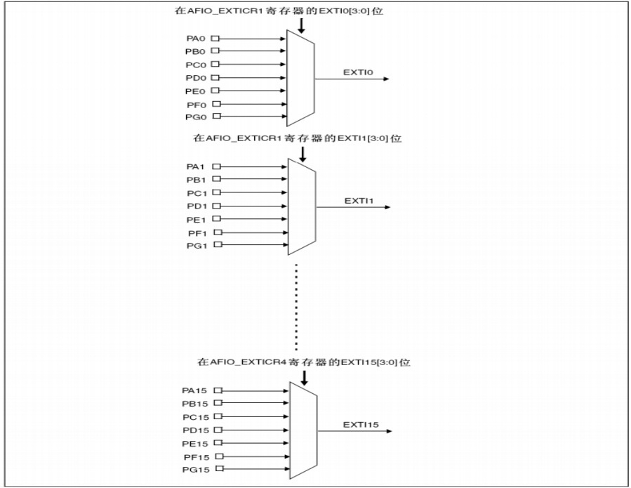
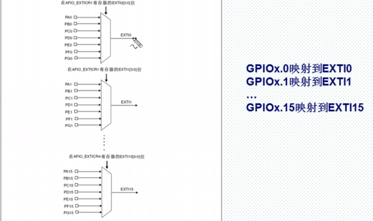
It can be seen from the above that STM32 has only 16 interrupt lines for IO ports, but STM32 has far more than 16 IO ports. So how does STM32 correspond the 16 interrupt lines to IO ports one by one? So STM32 is designed in this way, and the discipline of GPIO is gpiox 0-GPIOx. 15 (x = a, B, C, D, e, F,G) correspond to interrupt lines 0 ~ 15 respectively. In this way, each interrupt line corresponds to up to 7 IO ports. Take line 0 as an example: it corresponds to gpioa 0,GPIOB.0,GPIOC.0,GPIOD.0,GPIOE.0,GPIOF.0,GPIOG.0 The medium break line can only be connected to one IO port at a time, so it is necessary to determine which GPIO the corresponding break line is configured to through configuration. Let's take a look at the mapping relationship between GPIO and interrupt line:
Interrupt trigger mode
Corresponding trigger mode
Rising edge trigger: the moment when the digital level changes from low level (digital "0") to high level (digital "1") is called rising edge. Rising edge trigger is the switching action when the signal has a rising edge. When the potential changes from low to high and triggers the change of output, it is called rising edge trigger. That is, when the measured signal potential is from low to high, that is, rising, it is called rising edge trigger.
Falling edge trigger: in digital circuit, the moment when the digital level changes from high level (digital "1") to low level (digital "0") is called falling edge. [1] Falling edge trigger is the switching action when the signal has a falling edge. When the potential changes from high to low and triggers the change of output, it is called falling edge trigger. That is, it is triggered when the measured signal potential drops from high to low, which is called falling edge trigger.
Edge trigger: it can be triggered by rising or falling
The rising edge trigger is to trigger an interrupt when the voltage changes from low to high
Falling edge trigger is to trigger interrupt when the voltage changes from high to low
External interrupt common library functions
- Set the mapping relationship between IO port and interrupt line
GPIO_EXTILineConfig(uint8_t GPIO_PortSource, uint8_t GPIO_PinSource);
- 1
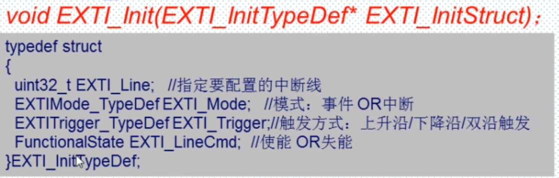
- Initialize interrupt line, trigger mode, etc
EXTI_Init(EXTI_InitTypeDef* EXTI_InitStruct);
- 1
- Judge whether the interrupt state of the interrupt line occurs
EXTI_GetITStatus(uint32_t EXTI_Line);
- 1
- Clear the interrupt flag bit on the interrupt line
EXTI_ClearITPendingBit(uint32_t EXTI_Line);
- 1
General configuration steps for external interrupts
General steps for external interrupt of IO port:
1 initialize IO port as input.
2. Turn on AFIO clock
3. Set the mapping relationship between IO port and interrupt line.
4 initialize online interrupt, set trigger conditions, etc. 5) Configure interrupt packet (NVIC) and enable interrupts.
6 write interrupt service function.
Through the above steps, we can use external interrupts normally.
Specific functions:
- Input of initialization IO
GPIO_Init(GPIO_TypeDef* GPIOx, GPIO_InitTypeDef* GPIO_InitStruct);
- 1
- Enable IO port multiplexing clock
RCC_APB2PeriphClockCmd(uint32_t RCC_APB2Periph, FunctionalState NewState);
- 1
- Set the mapping relationship between IO port and interrupt line
GPIO_EXTILineConfig(uint8_t GPIO_PortSource, uint8_t GPIO_PinSource);
- 1
- The initial telephone line is interrupted, and the trigger conditions are set
EXTI_Init(EXTI_InitTypeDef* EXTI_InitStruct);
- 1
- Configure interrupt packet (NVIC) and enable interrupts
NVIC_Init(NVIC_InitTypeDef* NVIC_InitStruct)
- 1
- Write interrupt service function
EXTI4_IRQHandler()
- 1
- Clear interrupt flag bit
EXTI_ClearITPendingBit(uint32_t EXTI_Line);
- 1
Key hardware connection diagram
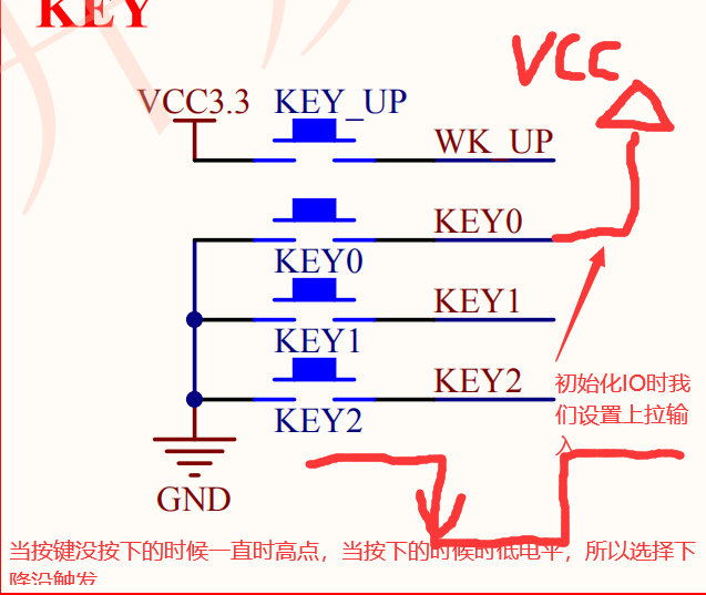
Key above_ Up is just set to pull-down input
Experimental code
External interrupt initialization code
Turn on multiplex clock
RCC_APB2PeriphClockCmd(RCC_APB2Periph_AFIO,ENABLE);//Turn on multiplex clock
- 1
Set the mapping relationship between IO port and interrupt line
/*Here, take key 0 (PE4 at IO port corresponding to key 0) as an example*/
	GPIO_EXTILineConfig(GPIO_PortSourceGPIOE,GPIO_PinSource4);
- 1
- 2
Initialize interrupt line, trigger mode, etc
	EXTI_InitTypeDef EXTI_InitTypeDefSture;
	EXTI_InitTypeDefSture.EXTI_Line    	=	EXTI_Line4;//Specifies the exi4 corresponding to the interrupt PE4 to be configured
	EXTI_InitTypeDefSture.EXTI_LineCmd	=	ENABLE;//Enable
	EXTI_InitTypeDefSture.EXTI_Mode			=	EXTI_Mode_Interrupt;//Select interrupt
	EXTI_InitTypeDefSture.EXTI_Trigger	=	EXTI_Trigger_Falling;//Falling edge trigger mode (combined with schematic diagram)
	EXTI_Init(&EXTI_InitTypeDefSture);
- 1
- 2
- 3
- 4
- 5
- 6
Configure interrupt packet (NVIC) and enable interrupts
	NVIC_InitTypeDef NVIC_InitStrue;
	NVIC_InitStrue.NVIC_IRQChannel										=	EXTI4_IRQn;
	NVIC_InitStrue.NVIC_IRQChannelCmd									= ENABLE;
	NVIC_InitStrue.NVIC_IRQChannelPreemptionPriority	=	0x02;//According to the settings in the main function
	NVIC_InitStrue.NVIC_IRQChannelSubPriority					= 0x02;
	NVIC_Init(&NVIC_InitStrue);
- 1
- 2
- 3
- 4
- 5
- 6
Interrupt service function
void EXTI4_IRQHandler(void)
{

	delay_ms(200);//Anti shake
	if(KEY0 == 0){//Judge whether the key KEY0 is pressed
		LED0 = !LED0;//Light reverse (light dims or DIMS)
		LED1 = !LED1;

	}
	EXTI_ClearITPendingBit(EXTI_Line4);// Clear interrupt flag bit


}
exti.c
#include "exti.h"
#include "key.h"
#include "led.h"
#include "delay.h"

void EXTI_Init()
{
	EXTI_InitTypeDef EXTI_InitTypeDefSture;
	NVIC_InitTypeDef NVIC_InitStrue;

	KEY_Init();
	RCC_APB2PeriphClockCmd(RCC_APB2Periph_AFIO,ENABLE);//Turn on multiplex clock

	/*Set the mapping relationship between IO port and interrupt line*/
	/*Here, take key 0 (PE4 at IO port corresponding to key 0) as an example*/
	GPIO_EXTILineConfig(GPIO_PortSourceGPIOE,GPIO_PinSource4);

	/* Initialize interrupt line, trigger mode, etc*/
	EXTI_InitTypeDefSture.EXTI_Line    	=	EXTI_Line4;//Specifies the exi4 corresponding to the interrupt PE4 to be configured
	EXTI_InitTypeDefSture.EXTI_LineCmd	=	ENABLE;//Enable
	EXTI_InitTypeDefSture.EXTI_Mode			=	EXTI_Mode_Interrupt;//Select interrupt
	EXTI_InitTypeDefSture.EXTI_Trigger	=	EXTI_Trigger_Falling;//Falling edge trigger mode (combined with schematic diagram)
	EXTI_Init(&EXTI_InitTypeDefSture);

	/*Configure interrupt packet (NVIC) and enable interrupts*/
	NVIC_InitStrue.NVIC_IRQChannel										=	EXTI4_IRQn;
	NVIC_InitStrue.NVIC_IRQChannelCmd									= ENABLE;
	NVIC_InitStrue.NVIC_IRQChannelPreemptionPriority	=	0x02;//According to the settings in the main function
	NVIC_InitStrue.NVIC_IRQChannelSubPriority					= 0x02;
	NVIC_Init(&NVIC_InitStrue);
}

void EXTI4_IRQHandler(void)
{

	delay_ms(200);//Anti shake
	if(KEY0 == 0){//Judge whether the key KEY0 is pressed
		LED0 = !LED0;Light reversing (dimming or dimming)
		LED1 = !LED1;

	}
	EXTI_ClearITPendingBit(EXTI_Line4);// Clear interrupt flag bit


}
main.c

```c
#include "stm32f10x.h"
#include "exti.h"
#include "led.h"
#include "key.h"
#include "delay.h"

int main(void)
{
	delay_init();
	NVIC_PriorityGroupConfig(NVIC_PriorityGroup_2);//Set NVIC interrupt packet 2: 2-bit preemption priority and 2-bit response priority
	KEY_Init();//Case initialization
	LED_Init();//Lamp initialization
	EXTIX_Init();//External interrupt initialization
	LED0 = 0;//Light on
	while(1);

}
Experimental effect
After power on, LED0 lights up. When KEY0 is pressed, LED0 goes out and LED1 lights up. After pressing again, LED0 lights up and LED1 goes out. (other keys can set relevant operations)
If you want the whole project file, you can chat privately