This article belongs to the production of STM32 balance car. It mainly discusses and analyzes how to use STM32 to output PWM, and use KEIL's own simulation logic analyzer to check the PWM waveform.
preface
As a saying goes, the best way to learn something is to speak it and record it yourself. The learning of STM32 balance car is a long cycle and a little difficult. Therefore, I want to know how to realize the project completely. It is very necessary to write CSDN. I won't say much nonsense here. I won't say much about the principle and concept of PWM. I will directly configure the steps.
1, Specific steps of firmware library configuration
In this configuration, we select timer 3 as the PWM output timer and CH2 as the output channel for configuration.
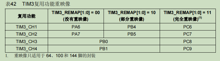
When configuring PWM output, special attention should be paid to the problem of multiplexing function remapping. Regardless of the problem of pin packaging, when TIM3 channel 2 corresponds to PA7 pin, remapping does not need to be considered. If PB5 is selected as the re image pin, partial re image is required. The specific problems will be reflected in the following code.
1. Enable timer and related IO port clock
      RCC_APB2PeriphClockCmd(RCC_APB2Periph_GPIOA,ENABLE);  //GPIOA enable
	  RCC_APB1PeriphClockCmd(RCC_APB1Periph_TIM3 ,ENABLE);    //Timer 3 clock enable
//  If PB5 is selected as the mapping, the following contents should also be included
//   GPIO_PeriphClockCmd(RCC_APB2Periph_AFIO,ENABLE);
//	 GPIO_PinRemapConfig(GPIO_PartialRemap_TIM3,ENABLE);     // Partial remapping
2. Initialize GPIO port_ Init();
 GPIO_InitTypeDef  GPIOAStruct;
 GPIOAStruct.GPIO_Mode=GPIO_Mode_AF_PP ;  //Multiplexed push-pull output
 GPIOAStruct.GPIO_Pin=GPIO_Pin_7;
 GPIOAStruct.GPIO_Speed=GPIO_Speed_50MHz;
 GPIO_Init(GPIOA, &GPIOAStruct);
3. Timer initialization TIM_TimeBaseInit();
      TIM_TimeBaseInitTypeDef TIM3Struct;	    //The timer is initialized and the count value is set to 99 + 1
	  TIM_DeInit(TIM3);          //TIM3 reset
      TIM3Struct.TIM_ClockDivision=TIM_CKD_DIV1  ;
	  TIM3Struct.TIM_CounterMode=TIM_CounterMode_Up;//Count up mode
	  TIM3Struct.TIM_Period=addr-1;        //Count value, modifiable
	  TIM3Struct.TIM_Prescaler=719;   //Frequency division value, modifiable
      TIM_TimeBaseInit(TIM3, &TIM3Struct);
4. Initialize the output comparison parameter TIM_OC2Init();
      TIM_OCInitTypeDef    TIM3_OCInitStruct;   //Initialize output comparison parameters
      TIM3_OCInitStruct.TIM_OCMode=TIM_OCMode_PWM2 ;  //Initialize output comparison. PWM2 mode means that the output value is valid when it is greater than the comparison value and invalid when it is less than.
      TIM3_OCInitStruct.TIM_Pulse=duty;      //If the comparison value is not fixed, this part can not be set
	  TIM3_OCInitStruct.TIM_OutputState=TIM_OutputState_Enable;
	  TIM3_OCInitStruct.TIM_OCPolarity=TIM_OCPolarity_High;
	  TIM_OC2Init(TIM3, &TIM3_OCInitStruct);  //Channel 2 initialization
5. Enable pre load register, timer
     TIM_OC2PreloadConfig(TIM3,TIM_OCPreload_Enable);
     TIM_Cmd(TIM3, ENABLE); //Enable timer
The whole configuration process does not involve timed interrupt.
2, Complete code
void GPIOA_Init()
 {

	 GPIO_InitTypeDef  GPIOAStruct;
     RCC_APB2PeriphClockCmd(RCC_APB2Periph_GPIOA,ENABLE);  //GPIOA enable
	 RCC_APB1PeriphClockCmd(RCC_APB1Periph_TIM3 ,ENABLE);    //Timer 3 clock enable
//  If PB5 is selected as the mapping, the following contents should also be included
//   GPIO_PeriphClockCmd(RCC_APB2Periph_AFIO,ENABLE);
//	 GPIO_PinRemapConfig(GPIO_PartialRemap_TIM3,ENABLE);     // Partial remapping
	                   //GPIOB port initialization
	 GPIOAStruct.GPIO_Mode=GPIO_Mode_AF_PP ;  //Multiplexed push-pull output
	 GPIOAStruct.GPIO_Pin=GPIO_Pin_7;
	 GPIOAStruct.GPIO_Speed=GPIO_Speed_50MHz;
     GPIO_Init(GPIOA, &GPIOAStruct);
 }
 void PWM_TIM3_CH2(u16 addr ,u16 duty)
 {
	  TIM_OCInitTypeDef    TIM3_OCInitStruct;   //Initialize output comparison parameters
      TIM_TimeBaseInitTypeDef TIM3Struct;	    //The timer is initialized and the count value is set to 99 + 1
	  TIM_DeInit(TIM3);          //TIM3 reset
      TIM3Struct.TIM_ClockDivision=TIM_CKD_DIV1  ;
	  TIM3Struct.TIM_CounterMode=TIM_CounterMode_Up;
	  TIM3Struct.TIM_Period=addr-1;        //Count value
	  TIM3Struct.TIM_Prescaler=719;   //Frequency division value
      TIM_TimeBaseInit(TIM3, &TIM3Struct);

      TIM3_OCInitStruct.TIM_OCMode=TIM_OCMode_PWM2 ;  //Initialize output comparison
      TIM3_OCInitStruct.TIM_Pulse=duty;      //If the comparison value is not fixed, this part can not be set
	  TIM3_OCInitStruct.TIM_OutputState=TIM_OutputState_Enable;
	  TIM3_OCInitStruct.TIM_OCPolarity=TIM_OCPolarity_High;
	  TIM_OC2Init(TIM3, &TIM3_OCInitStruct);  //Channel 2 initialization
      TIM_OC2PreloadConfig(TIM3,TIM_OCPreload_Enable);
      TIM_Cmd(TIM3, ENABLE); //Enable timer
 }
 int  main()
 {
   GPIOA_Init();
	 PWM_TIM3_CH2( 100,30);
	 while(1)
	 {
	 }
 return 0;
 }
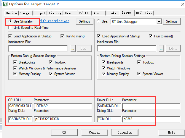
3, KEIL logic analyzer is used.
step1 is configured according to the following figure
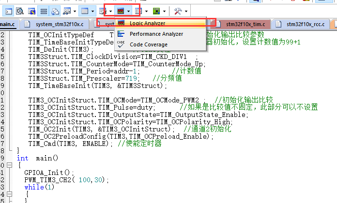
step2 click the debug button in the red box.
Step 3 Click logic analyzer
step4 follow the steps below. First click step, and then a window will pop up. Click Mark 2 in the figure to add options. Enter PORTA.7 and press enter.
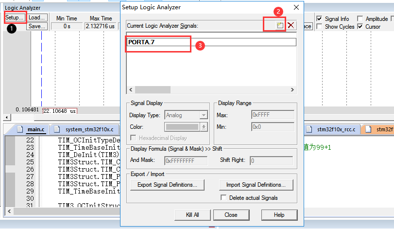
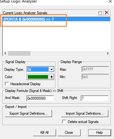
Step 5 press the Enter key to automatically generate the contents shown in the box. The content to be configured is also visible in the figure.
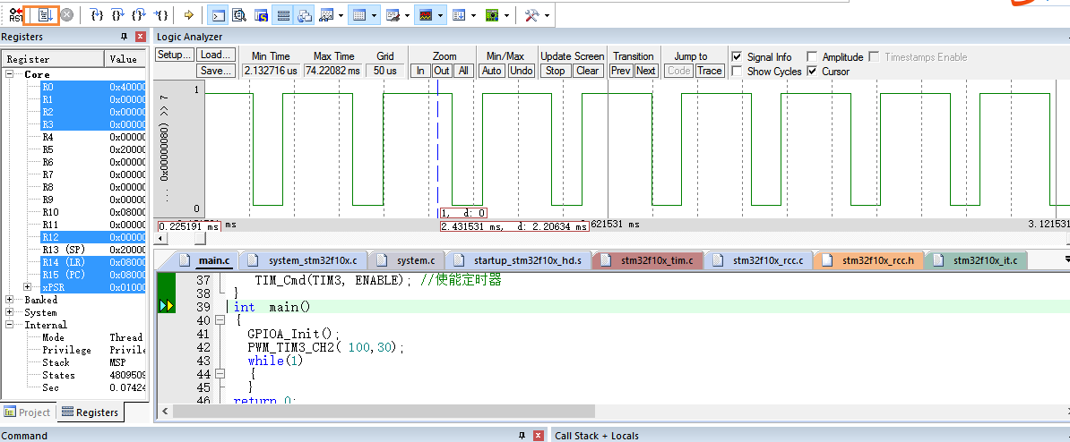
step6 click the run button to observe the PWM output waveform.
summary
The above is what I want to talk about today, which will be analyzed in STM32 learning later.