HC-05 Bluetooth serial communication
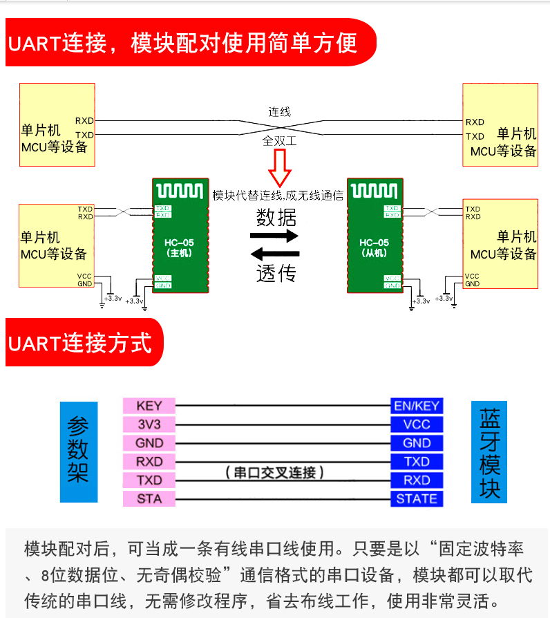
HC05 module is a high-performance master-slave Bluetooth serial port module. It is a PCBA board integrating Bluetooth function. It is very convenient for short-range wireless communication.
It can be seen from a treasure merchant that Bluetooth can be used in many ways. Here I use Bluetooth host connection, so we need to prepare the following devices:
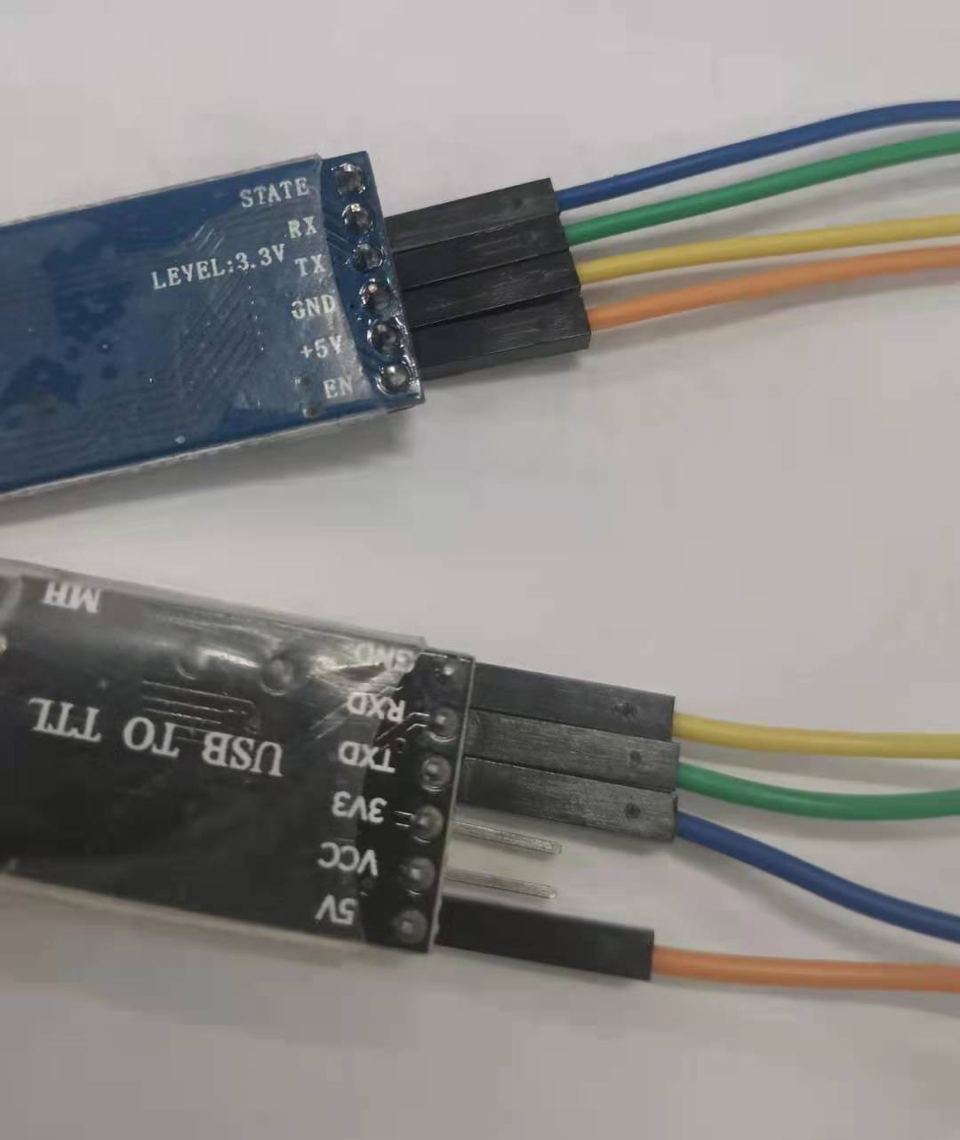
Two HC-05 Bluetooth modules, one USB-TTL and STM32F103ZET6.
In addition, prepare the serial port debugging assistant:
XCOMV2.0
Before configuring the Bluetooth module, you need to understand the debugging of the Bluetooth module.
HC-05 Bluetooth serial communication module has two working modes: command response working mode and automatic connection working mode. In the automatic connection mode, the module can be divided into
There are three working roles: Master, Slave and Loopback.
When the module is in the automatic connection mode, it will automatically connect the data transmission according to the preset mode;
When the module is in command response mode, it can execute at commands. Users can send various AT commands to the module, set control parameters or issue control commands for the module
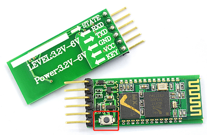
By default, the module is a slave and needs to be switched to the host through the AT command. There is a small key in the module. Press and hold the key to relax and power on, and observe the light on the Bluetooth. When the light flashes quickly, it is the automatic connection working mode. When the light flashes slowly, it enters the command response working mode.
Enter the command response working mode and configure it through AT command
Refer to Blogger configuration here.
https://blog.csdn.net/seek97/article/details/81333701
Bluetooth 1 (host)
AT+ORGL
AT+PSWD="123456"
AT+ROLE=1
Bluetooth 2 (slave)
AT+ORGL
AT+PSWD="123456"
AT+ROLE=0
AT+ADDR?
//The address of Bluetooth 2 is returned here: 98d3:35:cd33
AT+UART=38400,0,0
//The serial baud rate of Bluetooth 2 is returned here: 38400,0,0
Bluetooth 1 (host)
AT+BIND=98d3,35,cd33
AT+BIND?
//The binding address is returned here: 98d3:35:cd33
AT+UART=38400,0,0
AT+UART?
//The serial baud rate of Bluetooth 1 is returned here: 38400,0,0
AT+CMODE=0
usart.c file configuration
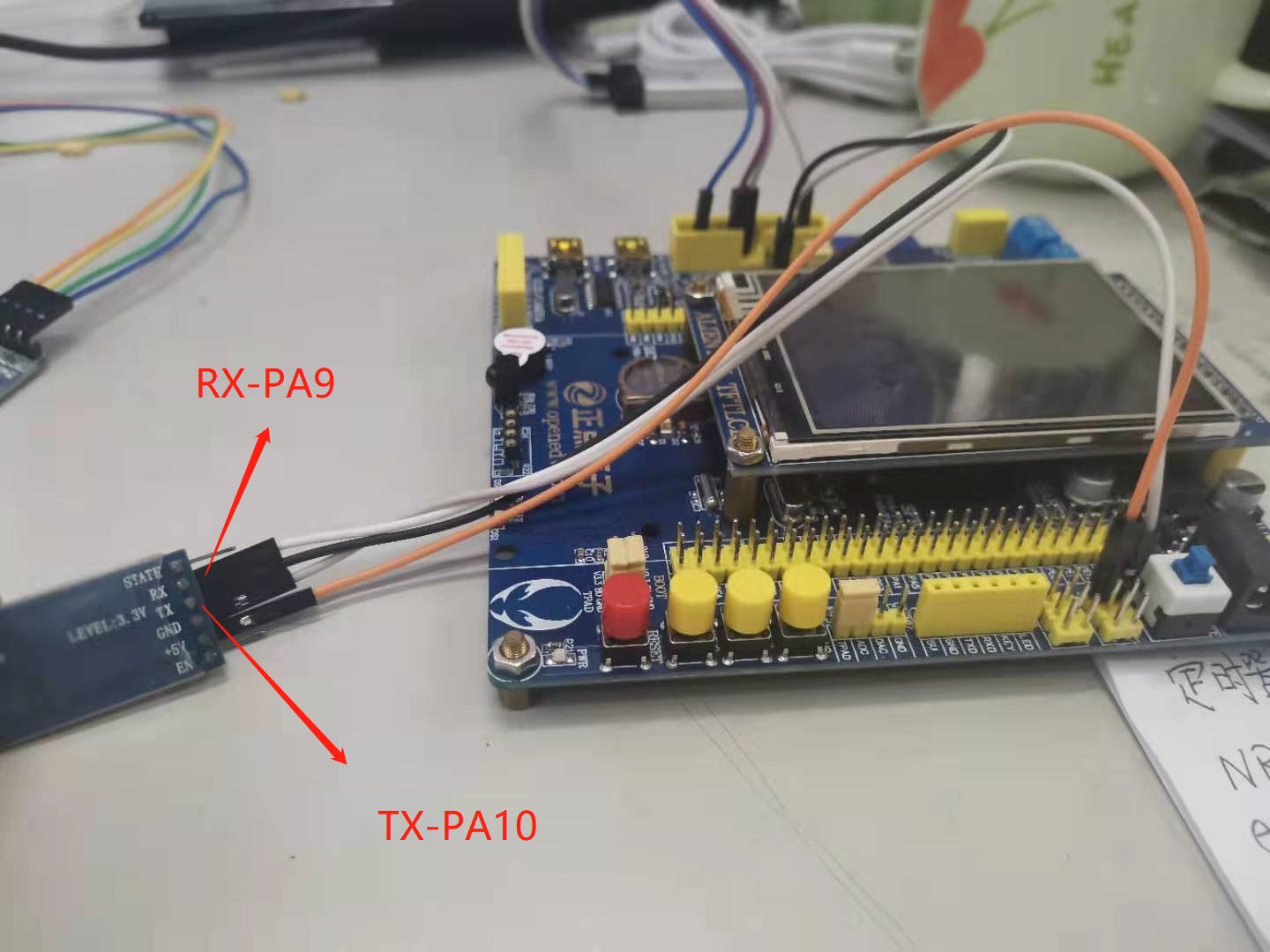
Configure the two Bluetooth modules according to the steps, and then the STM32 serial port code. There is nothing to talk about here. Here, use the punctual atomic code. Pay attention to the baud rate. It is the same as the serial port.
#include "sys.h"
#include "usart.h"
//
//If ucos is used, include the following header file
#if SYSTEM_SUPPORT_OS
#include "includes.h" 					// ucos usage
#endif

//
//Add the following code to support the printf function without selecting use MicroLIB
#if 1
#pragma import(__use_no_semihosting)
//Support functions required by the standard library
struct __FILE
{
	int handle;

};

FILE __stdout;
//Definition_ sys_exit() to avoid using half host mode
void _sys_exit(int x)
{
	x = x;
}
//Redefine fputc function
int fputc(int ch, FILE *f)
{
	while((USART1->SR&0X40)==0);//Cycle sending until sending is completed
    USART1->DR = (u8) ch;
	return ch;
}
#endif

#if EN_USART1_RX / / if receive is enabled
//Serial port 1 interrupt service program
//Note that reading usartx - > SR can avoid inexplicable errors
u8 USART_RX_BUF[USART_REC_LEN];     //Receive buffer, maximum USART_REC_LEN bytes
//Receiving status
//bit15, 	 Reception completion flag
//bit14, 	 0x0d received
//bit13~0, 	 Number of valid bytes received
u16 USART_RX_STA=0;       //Receive status flag

void uart1_init(u32 bound){
  //GPIO port settings
  GPIO_InitTypeDef GPIO_InitStructure;
	USART_InitTypeDef USART_InitStructure;
	NVIC_InitTypeDef NVIC_InitStructure;

	RCC_APB2PeriphClockCmd(RCC_APB2Periph_USART1|RCC_APB2Periph_GPIOA, ENABLE);	//Enable USART1, GPIOA clock

	//USART1_TX   GPIOA.9
  GPIO_InitStructure.GPIO_Pin = GPIO_Pin_9; //PA.9
  GPIO_InitStructure.GPIO_Speed = GPIO_Speed_50MHz;
  GPIO_InitStructure.GPIO_Mode = GPIO_Mode_AF_PP;	//Multiplexed push-pull output
  GPIO_Init(GPIOA, &GPIO_InitStructure);//Initialize gpioa nine

  //USART1_RX 	   GPIOA.10 initialization
  GPIO_InitStructure.GPIO_Pin = GPIO_Pin_10;//PA10
  GPIO_InitStructure.GPIO_Mode = GPIO_Mode_IN_FLOATING;//Floating input
  GPIO_Init(GPIOA, &GPIO_InitStructure);//Initialize gpioa ten

  //Usart1 NVIC configuration
  NVIC_InitStructure.NVIC_IRQChannel = USART1_IRQn;
	NVIC_InitStructure.NVIC_IRQChannelPreemptionPriority=3 ;//Preemption priority 3
	NVIC_InitStructure.NVIC_IRQChannelSubPriority = 3;		//Sub priority 3
	NVIC_InitStructure.NVIC_IRQChannelCmd = ENABLE;			//IRQ channel enable
	NVIC_Init(&NVIC_InitStructure);	//Initializes the VIC register according to the specified parameters

   //USART initialization settings

	USART_InitStructure.USART_BaudRate = bound;//Serial baud rate
	USART_InitStructure.USART_WordLength = USART_WordLength_8b;//The word length is in 8-bit data format
	USART_InitStructure.USART_StopBits = USART_StopBits_1;//A stop bit
	USART_InitStructure.USART_Parity = USART_Parity_No;//No parity bit
	USART_InitStructure.USART_HardwareFlowControl = USART_HardwareFlowControl_None;//No hardware data flow control
	USART_InitStructure.USART_Mode = USART_Mode_Rx | USART_Mode_Tx;	//Transceiver mode

  USART_Init(USART1, &USART_InitStructure); //Initialize serial port 1
  USART_ITConfig(USART1, USART_IT_RXNE, ENABLE);//Open serial port to accept interrupt
  USART_Cmd(USART1, ENABLE);                    //Enable serial port 1

}
void USART1_IRQHandler(void)                	//Serial port 1 interrupt service program
{
	u8 Res;
//	static u8 i =0;
#if SYSTEM_SUPPORT_OS  		// If system_ SUPPORT_ If OS is true, you need to support OS
	OSIntEnter();
#endif
	if(USART_GetITStatus(USART1, USART_IT_RXNE) != RESET)  //Receive interrupt (the received data must end in 0x0D and 0x0a)
		{
		 Res =USART_ReceiveData(USART1);	//Read received data
//	   USART_SendData(USART1,Res);
		if((USART_RX_STA&0x8000)==0)//Reception incomplete
			{
			if(USART_RX_STA&0x4000)//0x0d received
				{
				if(Res!=0x0a)USART_RX_STA=0;//Receive error, restart
				else USART_RX_STA|=0x8000;	//Reception is complete
				}
			else //I haven't received 0X0D yet
				{
				if(Res==0x0d)USART_RX_STA|=0x4000;
				else
					{
					USART_RX_BUF[USART_RX_STA&0X3FFF]=Res ;
					USART_RX_STA++;
					if(USART_RX_STA>(USART_REC_LEN-1))USART_RX_STA=0;//Error receiving data, restart receiving
					}
				}
			}
     }
#if SYSTEM_SUPPORT_OS  	// If system_ SUPPORT_ If OS is true, you need to support OS
	OSIntExit();
#endif
}
usart.h configuration
#ifndef __USART_H
#define __USART_H
#include "stdio.h"
#include "sys.h"
#define USART_REC_LEN   			 two hundred 	// Define the maximum number of bytes received 200
#define EN_USART1_RX  			 one 		// Enable (1) / disable (0) serial port 1 reception

extern u8  USART_RX_BUF[USART_REC_LEN]; //Receive buffer, maximum USART_REC_LEN bytes The last byte is a newline character
extern u16 USART_RX_STA;         		//Receive status flag

void uart1_init(u32 bound);
#endif
main.c configuration
#include "sys.h"
#include "delay.h"
#include "usart.h"

int main(void)
{
	NVIC_PriorityGroupConfig(NVIC_PriorityGroup_2);//Set the interrupt priority group as 2: 2-bit preemption priority and 2-bit response priority
	delay_init();	    	 //Delay function initialization
	uart1_init(38400);   //The baud rate of Bluetooth serial port is initialized to 38400
  while(1)
	{
        if(USART_RX_STA&0x8000)
		{
			len=USART_RX_STA&0x3fff;//Get the length of the data received this time
			printf("\r\n The message you sent is:\r\n\r\n");
			for(t=0;t<len;t++)
			{
				USART_SendData(USART1, USART_RX_BUF[t]);//Send data to serial port 1
				while(USART_GetFlagStatus(USART1,USART_FLAG_TC)!=SET);//Wait for sending to end
			}
			printf("\r\n\r\n");//Insert wrap
			USART_RX_STA=0;
		}
	}
}
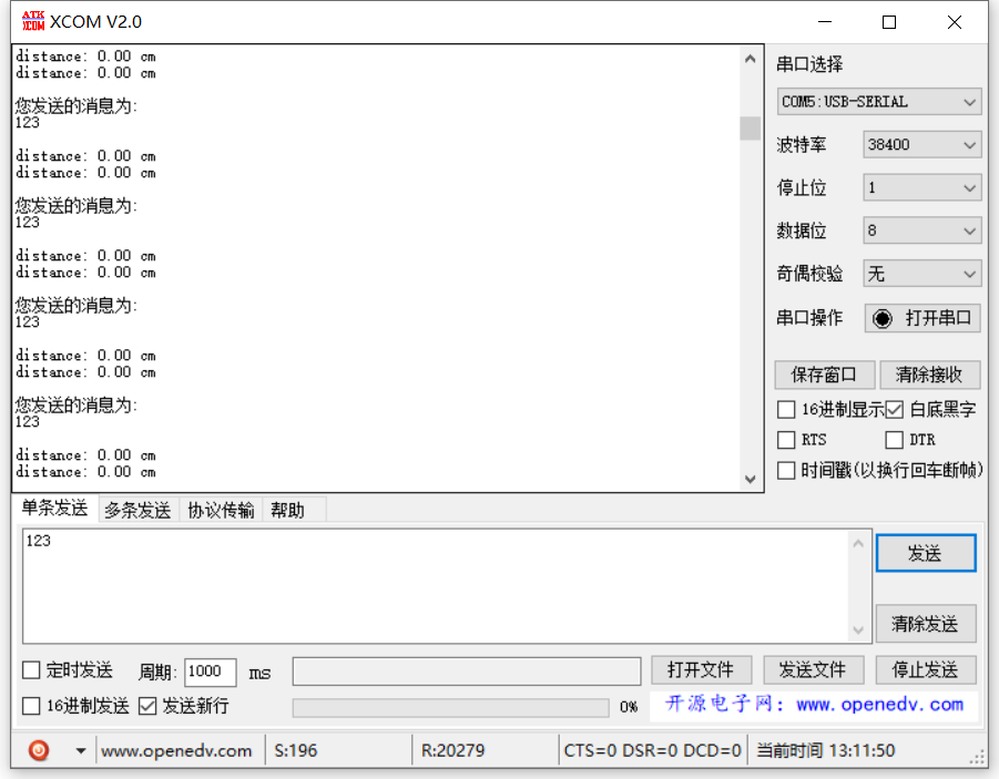
result
Power on the two Bluetooth and observe the flashing light. Both of them enter the automatic connection working mode. At the computer end, you can see the data sent back by stm32 through the serial port to the Bluetooth at the computer end. And tested the serial port interrupt, there is no problem.
Reference blog:
https://yngzmiao.blog.csdn.net/article/details/80368485
https://blog.csdn.net/seek97/article/details/81333701