STM32 input capture function uses TIM2 and TIM3 to capture 8-channel waveforms at the same time.
One of the requirements of work is to collect two groups of signals to control the stepping motor. It is to collect the square wave of 8 channels, measure the frequency and count the number of pulses. What looks simple has been bumping and bumping for two days and taken some detours. Write it down here and record it. By the way, understand that there are several uses of input capture.
1. Hardware design
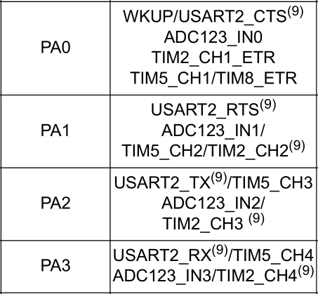
First, let's take a look at those IO ports. Find timx like this in the STM32 manual_ CHX is the input capture port.
Four ports of TIM2 and four ports of TIM3 are used here.
| definition | port |
|---|---|
| TIM2_CH1 | PA0 |
| TIM2_CH2 | PA1 |
| TIM2_CH3 | PA2 |
| TIM2_CH4 | PA3 |
| TIM3_CH1 | PA6 |
| TIM3_CH2 | PA7 |
| TIM3_CH3 | PB0 |
| TIM3_CH3 | PB1 |
2. Timer and input capture configuration (initialization)
It is relatively long. It can be roughly divided into initialization clock, initialization port, initialization timer, configuration of interrupt priority, setting of rising edge, enabling interrupt and timer.
Call in main program
TIM2_Cap_Init(0XFFFF,72-1); //Frequency counting at 1MHz
Q: How to calculate the time of the timer?
A: 72000000/72=1000000
TIM_ICInitTypeDef  TIM_ICInitStructure;
void TIM2_Cap_Init(u16 arr,u16 psc)
{
	GPIO_InitTypeDef GPIO_InitStructure;
	TIM_TimeBaseInitTypeDef  TIM_TimeBaseStructure;
 	NVIC_InitTypeDef NVIC_InitStructure;

	RCC_APB1PeriphClockCmd(RCC_APB1Periph_TIM2,ENABLE);	//Enable timer 2 clock
	RCC_APB1PeriphClockCmd(RCC_APB1Periph_TIM3,ENABLE);	//Enable timer 3 clock
 	RCC_APB2PeriphClockCmd(RCC_APB2Periph_GPIOA,ENABLE);  //Enable GPIOA clock
 	RCC_APB2PeriphClockCmd(RCC_APB2Periph_GPIOB,ENABLE);  //Enable GPIOB clock

	GPIO_InitStructure.GPIO_Pin  = GPIO_Pin_0 | GPIO_Pin_1 | GPIO_Pin_2 | GPIO_Pin_3 | GPIO_Pin_6 | GPIO_Pin_7;  //
	GPIO_InitStructure.GPIO_Mode = GPIO_Mode_IPD; //Set to input and pull down all
	GPIO_Init(GPIOA,&GPIO_InitStructure);
	GPIO_ResetBits(GPIOA,GPIO_Pin_0);
	GPIO_ResetBits(GPIOA,GPIO_Pin_1);
	GPIO_ResetBits(GPIOA,GPIO_Pin_2);
	GPIO_ResetBits(GPIOA,GPIO_Pin_3);
	GPIO_ResetBits(GPIOA,GPIO_Pin_6);
	GPIO_ResetBits(GPIOA,GPIO_Pin_7);

	GPIO_InitStructure.GPIO_Pin  = GPIO_Pin_0 | GPIO_Pin_1;  //
	GPIO_InitStructure.GPIO_Mode = GPIO_Mode_IPD; //Set to input and pull down all
	GPIO_Init(GPIOB,&GPIO_InitStructure);
	GPIO_ResetBits(GPIOB,GPIO_Pin_0);
	GPIO_ResetBits(GPIOB,GPIO_Pin_1);

	//Initialize timer 2
	TIM_TimeBaseStructure.TIM_Period = arr; //Set auto reload value
	TIM_TimeBaseStructure.TIM_Prescaler = psc; 	//Setup and distributor
	TIM_TimeBaseStructure.TIM_ClockDivision = TIM_CKD_DIV1; //Set clock division
	TIM_TimeBaseStructure.TIM_CounterMode = TIM_CounterMode_Up;  //Set up count
	TIM_TimeBaseInit(TIM2,&TIM_TimeBaseStructure); //Configure TIM2
	TIM_TimeBaseInit(TIM3,&TIM_TimeBaseStructure); //Configure TIM3

	//Initialize input capture parameters
	TIM_ICInitStructure.TIM_Channel = TIM_Channel_1; //Select input port 1: CH1
  	TIM_ICInitStructure.TIM_ICPolarity = TIM_ICPolarity_Rising;	//Rising edge capture
  	TIM_ICInitStructure.TIM_ICSelection = TIM_ICSelection_DirectTI; //Map to TI1
  	TIM_ICInitStructure.TIM_ICPrescaler = TIM_ICPSC_DIV1;	 //Configure allocation as no allocation
  	TIM_ICInitStructure.TIM_ICFilter = 0x00;//Configure input filtering as no filtering
  	TIM_ICInit(TIM2,&TIM_ICInitStructure);
  	TIM_ICInit(TIM3,&TIM_ICInitStructure);

	//The following are the same, so I won't explain them one by one.
	TIM_ICInitStructure.TIM_Channel = TIM_Channel_2;
  	TIM_ICInitStructure.TIM_ICPolarity = TIM_ICPolarity_Rising;
  	TIM_ICInitStructure.TIM_ICSelection = TIM_ICSelection_DirectTI;
  	TIM_ICInitStructure.TIM_ICPrescaler = TIM_ICPSC_DIV1;
  	TIM_ICInitStructure.TIM_ICFilter = 0x00;
  	TIM_ICInit(TIM2,&TIM_ICInitStructure);
  	TIM_ICInit(TIM3,&TIM_ICInitStructure);

	TIM_ICInitStructure.TIM_Channel = TIM_Channel_3;
  	TIM_ICInitStructure.TIM_ICPolarity = TIM_ICPolarity_Rising;
  	TIM_ICInitStructure.TIM_ICSelection = TIM_ICSelection_DirectTI;
 	 TIM_ICInitStructure.TIM_ICPrescaler = TIM_ICPSC_DIV1;
  	TIM_ICInitStructure.TIM_ICFilter = 0x00;
  	TIM_ICInit(TIM2,&TIM_ICInitStructure);
  	TIM_ICInit(TIM3,&TIM_ICInitStructure);

	TIM_ICInitStructure.TIM_Channel = TIM_Channel_4;
  	TIM_ICInitStructure.TIM_ICPolarity = TIM_ICPolarity_Rising;
  	TIM_ICInitStructure.TIM_ICSelection = TIM_ICSelection_DirectTI;
  	TIM_ICInitStructure.TIM_ICPrescaler = TIM_ICPSC_DIV1;
  	TIM_ICInitStructure.TIM_ICFilter = 0x00;
  	TIM_ICInit(TIM2,&TIM_ICInitStructure);
  	TIM_ICInit(TIM3,&TIM_ICInitStructure);

	//Interrupt packet priority initialization
	NVIC_InitStructure.NVIC_IRQChannel = TIM2_IRQn;  //TIM2 interrupt
	NVIC_InitStructure.NVIC_IRQChannelPreemptionPriority = 2;  //Preemptive priority 2
	NVIC_InitStructure.NVIC_IRQChannelSubPriority = 2;  //From priority 2
	NVIC_InitStructure.NVIC_IRQChannelCmd = ENABLE; //IRQ channel enabled
	NVIC_Init(&NVIC_InitStructure);  //Configuration register

	NVIC_InitStructure.NVIC_IRQChannel = TIM3_IRQn;  //TIM3 interrupt
	NVIC_InitStructure.NVIC_IRQChannelPreemptionPriority = 3;  //Preemptive priority 3
	NVIC_InitStructure.NVIC_IRQChannelSubPriority = 3;  //From priority 3
	NVIC_InitStructure.NVIC_IRQChannelCmd = ENABLE; //IRQ channel enabled
	NVIC_Init(&NVIC_InitStructure);  //Configuration register

	//All 8 channels are set to capture the rising edge
	TIM_OC1PolarityConfig(TIM2,TIM_ICPolarity_Rising);
	TIM_OC2PolarityConfig(TIM2,TIM_ICPolarity_Rising);
	TIM_OC3PolarityConfig(TIM2,TIM_ICPolarity_Rising);
	TIM_OC4PolarityConfig(TIM2,TIM_ICPolarity_Rising);

	TIM_OC1PolarityConfig(TIM3,TIM_ICPolarity_Rising);
	TIM_OC2PolarityConfig(TIM3,TIM_ICPolarity_Rising);
	TIM_OC3PolarityConfig(TIM3,TIM_ICPolarity_Rising);
	TIM_OC4PolarityConfig(TIM3,TIM_ICPolarity_Rising);

	//Allow update interrupt and CCxIE capture interrupt
	TIM_ITConfig(TIM2,TIM_IT_Update|TIM_IT_CC1|TIM_IT_CC2|TIM_IT_CC3|TIM_IT_CC4,ENABLE);//
	TIM_ITConfig(TIM3,TIM_IT_Update|TIM_IT_CC1|TIM_IT_CC2|TIM_IT_CC3|TIM_IT_CC4,ENABLE);//
	//Enable timer
 	TIM_Cmd(TIM2,ENABLE);
 	TIM_Cmd(TIM3,ENABLE);
}
3. Interrupt function
Here is an example, TIM2_CH1, other copy and paste, just change it.
The idea of capturing square wave is to capture two rising edges, and the time difference between the two rising edges is the period. The reciprocal of the cycle is the frequency.
u8  TIMCH_STA[8] = {0};	//Flag digit group
u16	TIMCH_VAL[8] = {0};	//Timer array
void TIM2_IRQHandler(void)
{
		if((TIMCH_STA[0]&0X80)==0)//A complete cycle has not been captured yet
		{
				if(TIM_GetITStatus(TIM2,TIM_IT_CC1) != RESET)//Capture event occurred in capture 1
				{
						if(TIMCH_STA[0]&0X40)		//Capture to second rising edge
						{
								TIMCH_STA[0]|=0X80;		//The tag captures a complete cycle and is processed by the main program
								TIMCH_VAL[0]=TIM_GetCapture1(TIM2);//Get event
						}
						else  								//Capture first rising edge
						{
								TIMCH_STA[0]=0;				 //Clear flag bit
								TIMCH_VAL[0]=0;				 //Clear timer
								TIM_SetCounter(TIM2,0);		 //Clear timer
								TIMCH_STA[0]|=0X40;		 //The tag captures the first rising edge
						}
				}
		}
}
The main program is very simple
for(i=0;i<8;i++)//Scan the flag bits of 8 channels
{
	if(TIMCH_STA[i]&0X80)//Successfully captured pulse
	{
		temp = TIMCH_VAL[i];	//Get cycle time
		printf("HIGH[%d]:%d us\r\n",i,temp);	//Printout
		TIMCH_STA[i]=0;			//Reset the flag bit and start the next capture
	}
}
4. Notes and extension instructions
1. Sampling accuracy
Input a frequency of 1KHz, and the number collected is 999us. That is 1.001KHz, and the rounding is 1KHz. Since the circuit is not filtered, the error is excusable.
2. Sampling range
Because the frequency of the timer is 1M, the sampling below 10KHz is more accurate. During the test, a 50KHz is given, and the sampled data is 19 nanoseconds, that is, 52.6KHz, which is not accurate. Moreover, the counter array is only U16 type, that is, if the frequency is less than 15.25HZ, it overflows.
Therefore, the sampling range of this program is 50Hz~5KHz. If you want to be large or small, you have to adjust the program. Just like the oscilloscope, it also needs to adjust the frequency.
3. If the duty cycle is to be adopted
The time of the first rising edge and the second rising edge is the cycle. The time of the first rising edge and the first falling edge is the time of the high level. Calculate the duty cycle.
When collecting the rising edge, change the capture to the falling edge, and when collecting the falling edge, change to the rising edge. The duty cycle can be calculated. However, in the actual test, the accuracy is checked, probably because changing the configuration capture in the interrupt will take time.
TIM_OC1PolarityConfig(TIM3,TIM_ICPolarity_Falling);//Capture falling edge.