1, Experimental principle
The whole process of interrupt is divided into interrupt occurrence → interrupt processing → interrupt return.
- Interrupt occurrence: when the CPU is processing an event A, another event B occurs and requests the CPU to handle it quickly.
- Interrupt processing: when the CPU receives the request, it pauses the current work and installs it to process event B.
- Interrupt return: when the CPU finishes processing event B, it returns to the suspended place in event A to continue processing event A.
Interrupt can solve the contradiction of data transmission between fast CPU and slow external devices, and can serve multiple external devices time-sharing to improve computer utilization; It can handle the random events of the application system in time and enhance the real-time performance of the system.
The function of DMA is to realize the direct transmission of data, which eliminates the link that the traditional data transmission requires the participation of CPU register. It mainly involves four kinds of data transmission, but it is essentially the same. It is transmitted from one area of memory to another area of memory (the data register of peripheral device is essentially a storage unit of memory). Data transmission in four cases is as follows:
Peripheral to memory
Memory to peripherals
Memory to memory
Peripheral to peripheral
Normal mode
After the transfer is completed (i.e. the number of data to be transferred reaches zero), DMA operations will no longer occur. if
To start a new DMA transfer, restart the DMA transfer when the DMA channel is closed.
Cycle mode
It can be used to process ring buffers and continuous data streams (such as ADC scan mode). When cycle is activated
After the ring mode, at the end of each round of transmission, the number of data to be transmitted will automatically use the set initial value
Load and continue to respond to DMA requests.
2, Interrupt control LED on and off
1. Project creation
For the new CubeMX project, after selecting the chip, set PA1 to output and PB1 to GPIO_EXTI1
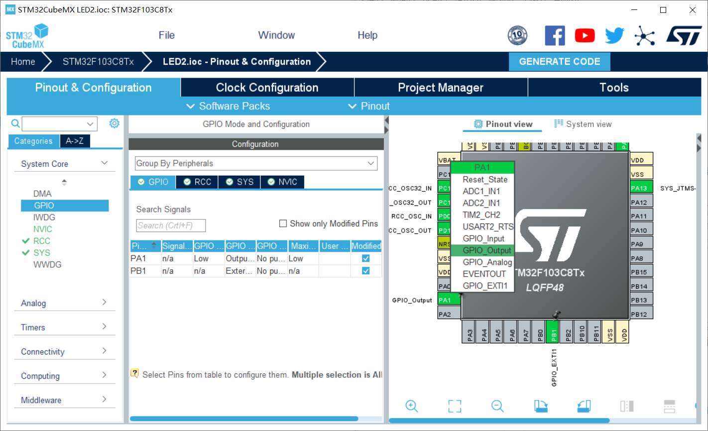
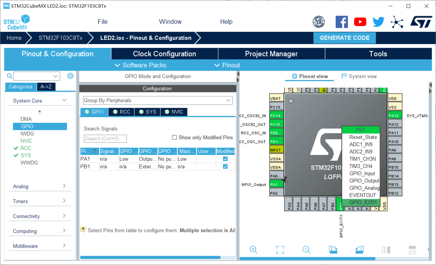
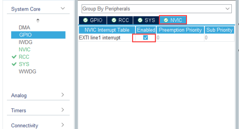
Interrupt enable
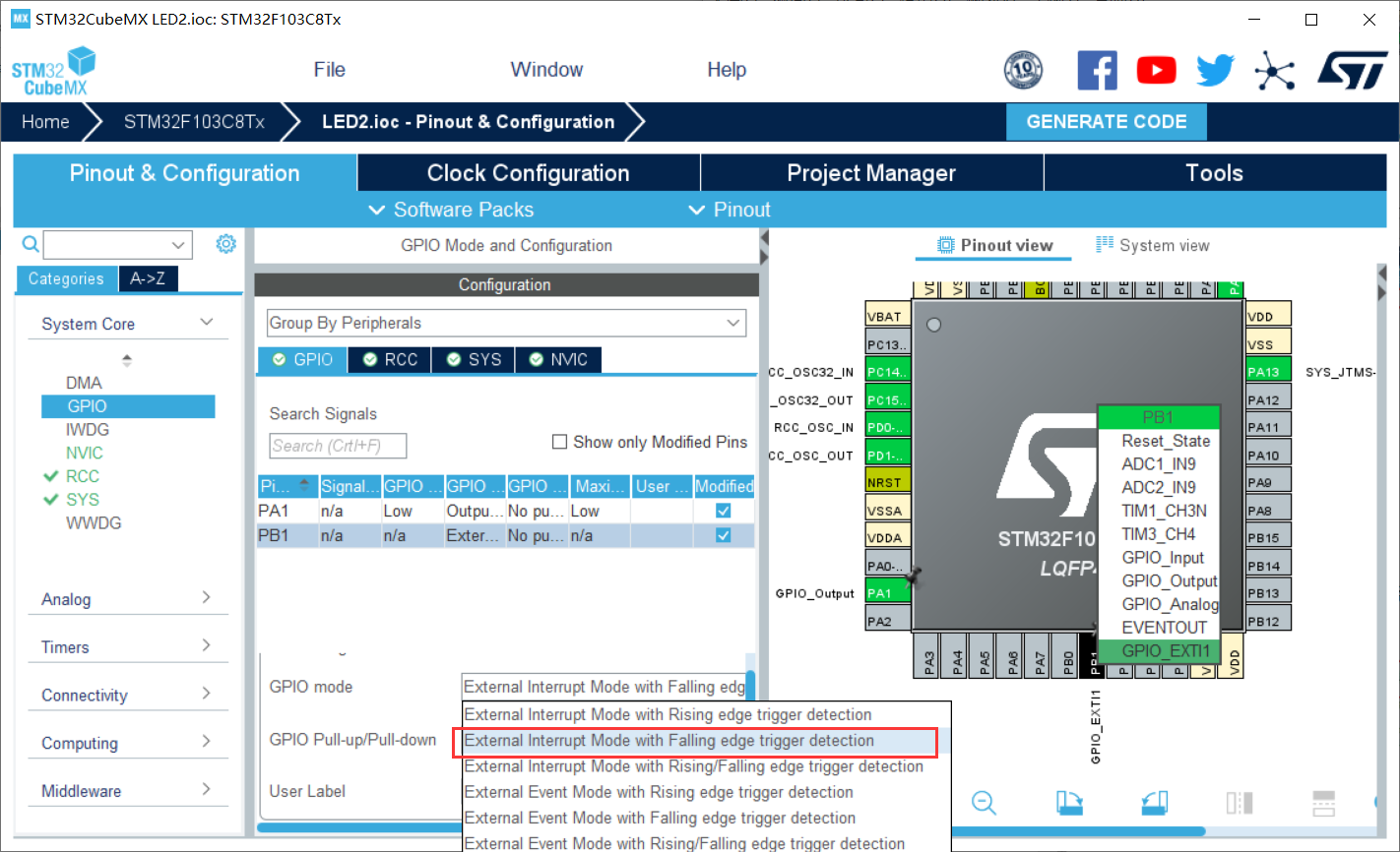
Set GPIO mode to falling edge
RCC settings are as follows
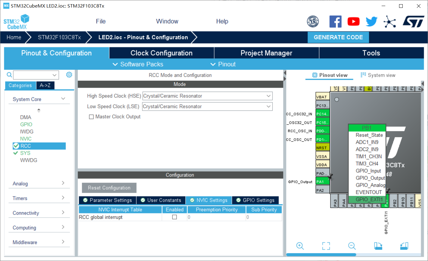
Check under Code Generator
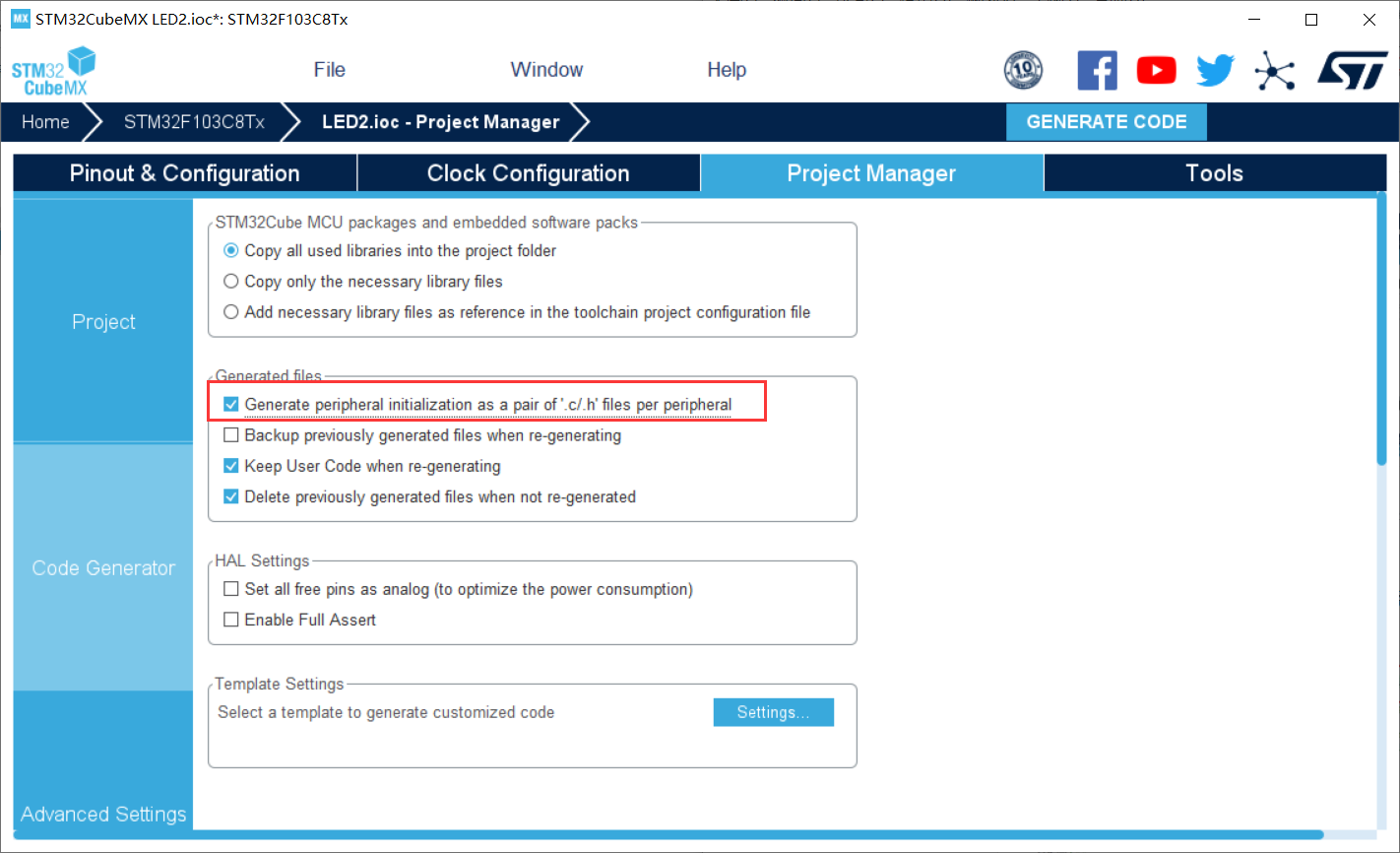
Then generate the code and open the project
2. Code implementation
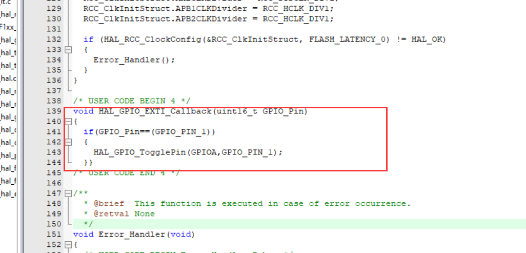
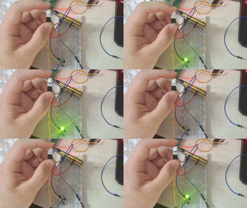
Idea: PB1 is connected to the switch and PA1 is connected to the LED lamp. At first, the LED is always on. When the switch is pressed, the LED goes out and the state of PA1 is reversed.
We are stm32f1xx_ hal_ You can view the system default callback function in GPIO. C
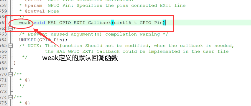
The function representation of the weak attribute: if the function is not defined in other files, use the function; if the user defines the function elsewhere, use the user-defined function.
We rewrite the callback function in the mian function
void HAL_GPIO_EXTI_Callback(uint16_t GPIO_Pin)
{
	if(GPIO_Pin==GPIO_PIN_1)	//Determine external interrupt source
	{
		HAL_GPIO_TogglePin(GPIOA,GPIO_PIN_1)//Flip PA1 status
	}}
3. Experimental effect
Burn the program into the chip
3, Serial communication (interrupt)
1. Project creation
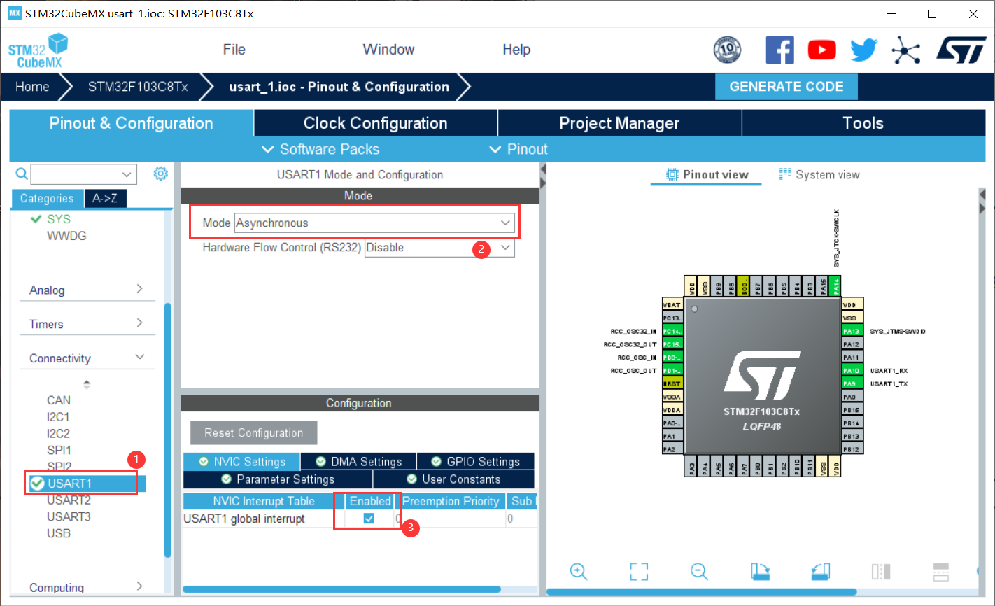
Create a new project, select the chip, find USART1 under Connectivity, select Asynchronous for Mode, and then check the enable below
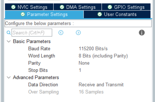
Set communication parameters in Parameter Settings, i.e. baud rate 115200, 8-bit data bits, no parity, 1-bit stop bit, enable reception and transmission, and 16 times oversampling.
The other settings are the same
2. Programming
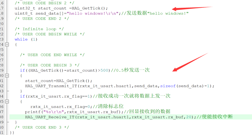
Idea: ① send data: send hello windows once in 0.5s in the main function, use HAL_UART_Transmit_IT function to send back the received characters as they are, and a callback will be generated after sending successfully; ② receive data: generate a callback HAL_UART_RxCpltCallback after receiving data, send the data once after receiving successfully, and then start receiving data again.
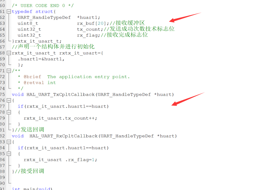
Define structure
//Defines the structure type of test serial port interrupt function transceiver
typedef struct{
	UART_HandleTypeDef	*huart1;
	uint8_t							rx_buf[20];//Receive buffer
	uint32_t						tx_count;//Number of successful transmission technical flag bits
	uint32_t						rx_flag;//Receive completion flag bit
}rxtx_it_usart_t;
//Declare a structure and initialize it
rxtx_it_usart_t	rxtx_it_usart={
	.huart1=&huart1,
	};
Serial port interrupt callback function
void HAL_UART_TxCpltCallback(UART_HandleTypeDef *huart)
{
	if(rxtx_it_usart.huart1==huart)
	{
		rxtx_it_usart.tx_count++;
	}
}//Send callback
void  HAL_UART_RxCpltCallback(UART_HandleTypeDef *huart)
{
	if(rxtx_it_usart.huart1==huart)
	{
		rxtx_it_usart .rx_flag=1;
	}
}//Accept callback
Add the following code to the main function
		if((HAL_GetTick()-start_count)>500)//Send once every 0.5 seconds
		{
			start_count=HAL_GetTick();
			HAL_UART_Transmit_IT(rxtx_it_usart.huart1,send_data,sizeof(send_data)-1);
		}
		if(rxtx_it_usart.rx_flag==1)//Send the data once after receiving it successfully
		{
				rxtx_it_usart.rx_flag=0;//Clear flag bit
			printf("%s\r\n",rxtx_it_usart.rx_buf);//Echo received data
			HAL_UART_Receive_IT(rxtx_it_usart.huart1,rxtx_it_usart.rx_buf,20);//Enable receive interrupt
  }
3. Experimental effect
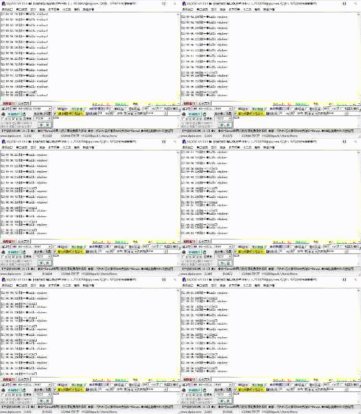
Serial port debugging assistant
4, DMA mode
1. Project creation
Under USART1, first set the Mode to Asynchronous, and then click Add twice to Add the DMA data streams received and sent by the serial port.
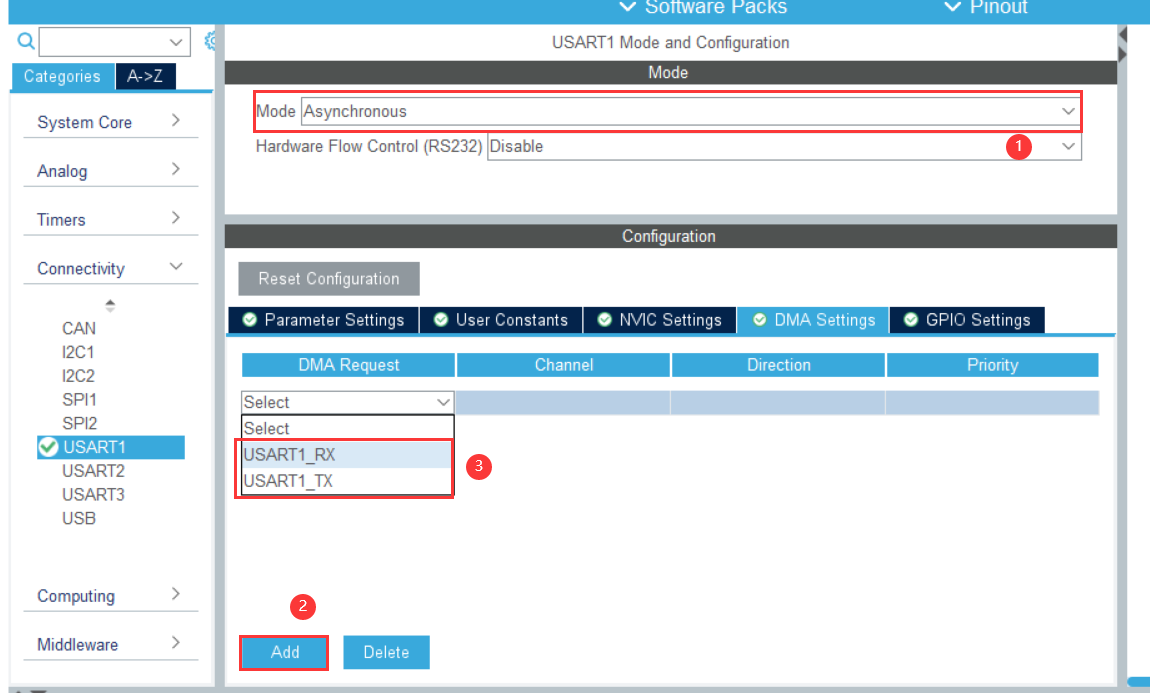
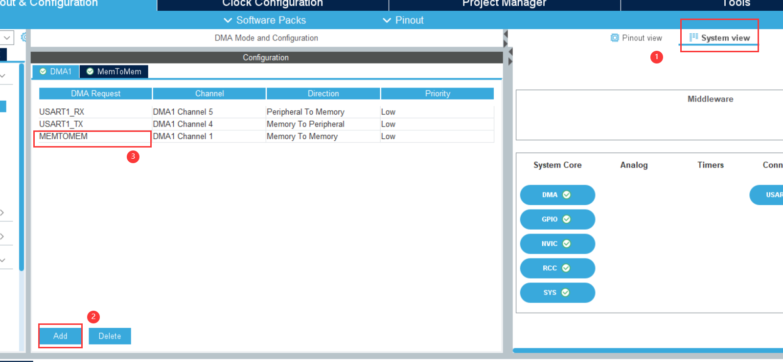
The interrupt enable of DMA data stream is automatically checked by CubeMX. We need to check the interrupt of enable serial port 1, and the interrupt priority uses the default value

Add MEMTOMEM
set clock
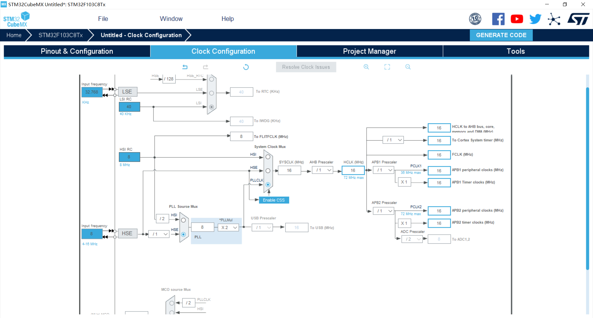
Then generate the code
2. Programming
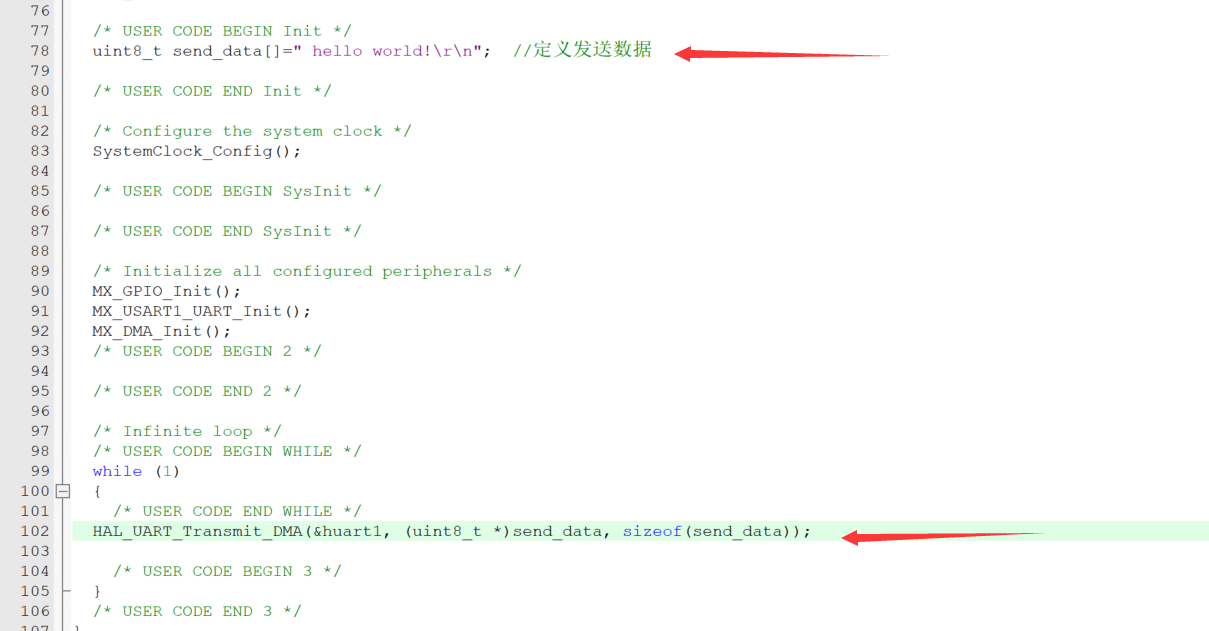
Open the project file and add the following code in main.c
First, set the sending data "hello world!"
uint8_t send_data[]=" hello world!\r\n"; //Define send data
then
HAL_UART_Transmit_DMA(&huart1, (uint8_t *)send_data, sizeof(send_data));
3. Experimental effect
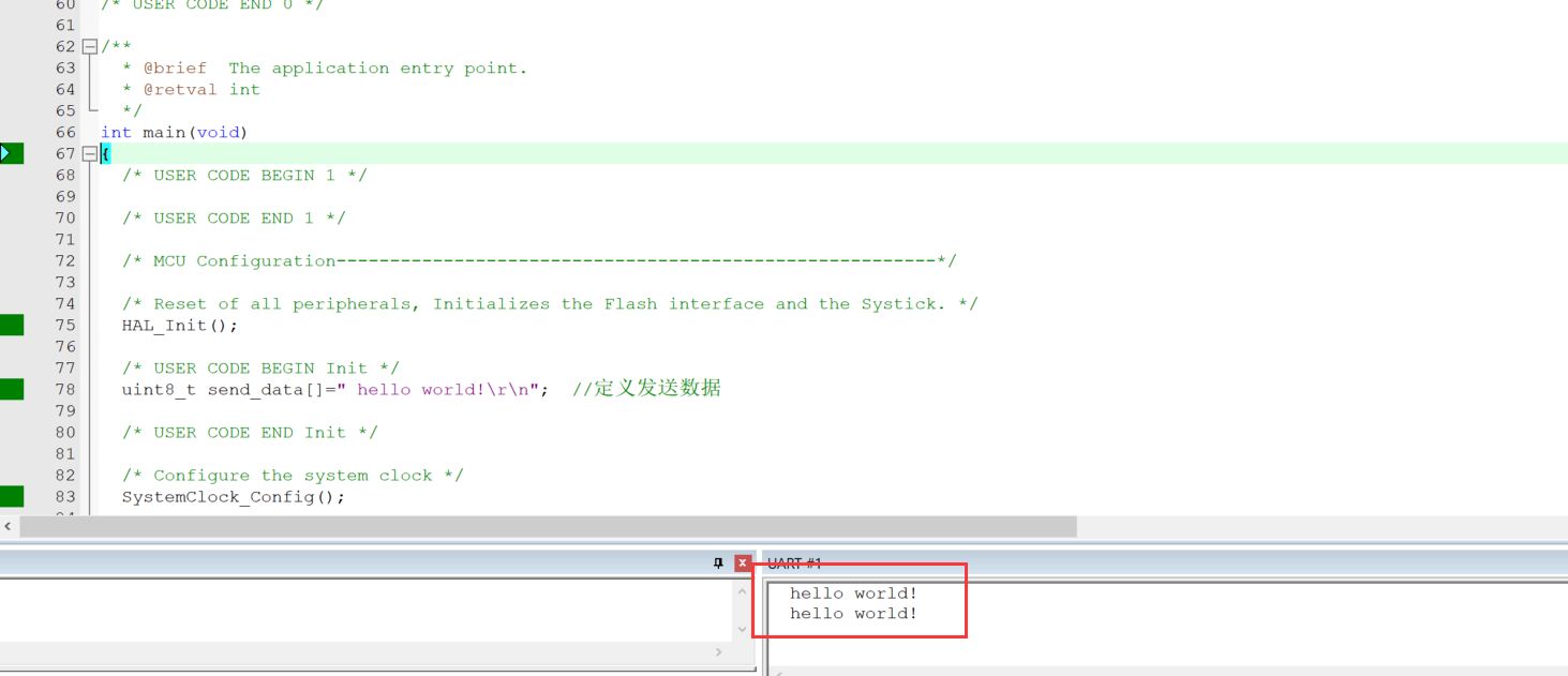
simulation result
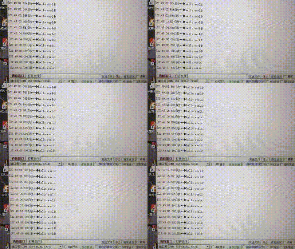
Serial assistant
5, Summary
In fact, this experiment is not very difficult, so no complex functions are designed. You can learn it well by learning the stm32 Chinese manual and library function manual, or through network resources. The DMA transmission process does not occupy CPU resources, and you can run other tasks while transmitting, which is more efficient.