STM32 learning from scratch @EnzoReventon
Detailed explanation of CAN communication code
Related links:
STM32 learning from scratch - physical layer of CAN communication protocol
CAN bus specification v2 0 version
Introduction to CAN bus
Zhou Ligong - Chinese version of CAN protocol
reference material:
[wildfire EmbedFire] practical guide for STM32 Library Development -- Based on wildfire Decepticon development board
[punctual atom] STM32F4 Development Guide - library function version_ V1. two
[ST] STM32F4xx Chinese Reference Manual
CAN bus specification v2 0 version
Introduction to CAN bus
Zhou Ligong - Chinese version of CAN protocol
======================================================
Some time ago, due to the busy affairs of the school, the shift was interrupted for some time. We understand that we will continue to share our learning notes in the future~
stay STM32 learning process from scratch - CAN related structures above In, we have introduced the relevant structures to be used in CAN communication in detail, so we won't repeat them here.
This paper mainly introduces the relevant codes of CAN communication experiment in detail. The development board used is the F4 development board of punctual atomic explorer. If there are deficiencies, please give us your advice~
Experimental purpose
- Two communication modes of CAN are used to transmit and receive data.
- Display the received and sent data and mode status by using the serial port debugging assistant.
- The data content sent is a random number, which is an increasing number of 0-255.
- Press KEY_RES realizes the switching of CAN mode.
- Press KEY_1. Realize the sending and receiving of primary data.
- The flashing LED indicates that the program is running normally.
hardware design
-
First, consult the chip Manual of STM32F407ZGT6 to understand the transceiver pin of CAN communication. In this experiment, we use PA11 and PA12 as RX and TX functions of CAN communication. The rest UART, keys and LED lights are ready-made on the development board. Users can choose according to the actual situation of their own development board. This configuration will not be explained in detail in this paper.
-
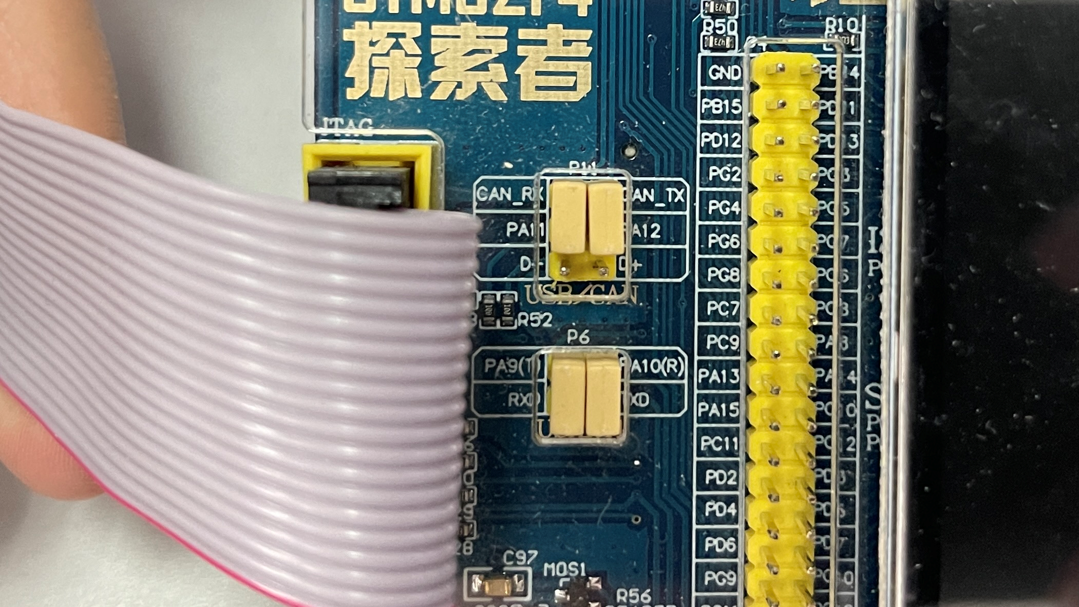
Connect PA11 and can with jumper cap_ RX connection, PA12 and CAN_TX connection. As shown in the figure below.
-
Connect JLINK and serial port to facilitate debugging.
Software design process
- CAN.c
- Initialize RCC clock
- Initialize GPIO
- Pin reuse
- Initialize CAN related structures
- Configure filter
- Initialization interrupt (if used)
- The transceiver structure of CAN is set with cantxmsg & canrxmsg
- main.c
- Call corresponding peripheral initialization functions (LED, UART, KEY, interrupt, CAN)
- Write the corresponding transceiver function
Code explanation
- can.h
//CAN1 receive RX0 interrupt enable
#define CAN1_RX0_INT_ENABLE 	                 0 				// 0, not enabled; 1. Enable

u8 CAN1_Mode_Init(u8 tsjw,u8 tbs2,u8 tbs1,u16 brp,u8 mode);	//CAN initialization

u8 CAN1_Send_Msg(u8* msg,u8 len);							//send data

u8 CAN1_Receive_Msg(u8 *buf);								//receive data
#endif
- can.c
- CAN initialization function.
//CAN initialization
//tsjw: resynchronize jump time unit Range: CAN_SJW_1tq~ CAN_SJW_4tq
//tbs2: time unit of time period 2 Range: CAN_BS2_1tq~CAN_BS2_8tq;
//tbs1: time unit of time period 1 Range: CAN_BS1_1tq ~CAN_BS1_16tq
//BRP: baud rate divider Range: 1~1024; tq=(brp)*tpclk1
//Baud rate = Fpclk1/((tbs1+1+tbs2+1+1)*brp);
//mode:CAN_Mode_Normal, normal mode; CAN_Mode_LoopBack, loopback mode;
//The clock of Fpclk1 is set to 42M during initialization. If Can1 is set_ Mode_ Init(CAN_SJW_1tq,CAN_BS2_6tq,CAN_BS1_7tq,6,CAN_Mode_LoopBack);
//Baud rate: 42M/((6+7+1)*6)=500Kbps
//Return value: 0, initialization OK;
//       Other, initialization failed;

u8 CAN1_Mode_Init(u8 tsjw,u8 tbs2,u8 tbs1,u16 brp,u8 mode)
{
	//Define structure variables
  	GPIO_InitTypeDef       GPIO_InitStructure;    	 	//GPIO initialization structure
	CAN_InitTypeDef        CAN_InitStructure;	   		//CAN initialization structure
  	CAN_FilterInitTypeDef  CAN_FilterInitStructure;		//CAN filter structure

	//Interrupt enable function, if you need to use interrupt, in can H is enabled in the header file, then the structure takes effect.
	#if CAN1_RX0_INT_ENABLE
	   	NVIC_InitTypeDef  NVIC_InitStructure;
	#endif


	//Enable correlation clock
	RCC_AHB1PeriphClockCmd(RCC_AHB1Periph_GPIOA, ENABLE);				//Enable GPIOA clock

  	RCC_APB1PeriphClockCmd(RCC_APB1Periph_CAN1, ENABLE);				//Enable CAN1 clock

	//Initialize GPIO
	GPIO_InitStructure.GPIO_Pin = GPIO_Pin_11| GPIO_Pin_12;
    GPIO_InitStructure.GPIO_Mode = GPIO_Mode_AF;						//Reuse function
    GPIO_InitStructure.GPIO_OType = GPIO_OType_PP;//Push pull output
    GPIO_InitStructure.GPIO_Speed = GPIO_Speed_100MHz;//100MHz
    GPIO_InitStructure.GPIO_PuPd = GPIO_PuPd_UP;//Pull up
    GPIO_Init(GPIOA, &GPIO_InitStructure);//Initialize PA11,PA12

	//Pin multiplexing mapping configuration
	GPIO_PinAFConfig(GPIOA,GPIO_PinSource11,GPIO_AF_CAN1); 				//GPIOA11 multiplexed to CAN1
	GPIO_PinAFConfig(GPIOA,GPIO_PinSource12,GPIO_AF_CAN1); 				//GPIOA12 multiplexed to CAN1

	//CAN unit setting
   	CAN_InitStructure.CAN_TTCM=DISABLE;									//Non time triggered communication mode
  	CAN_InitStructure.CAN_ABOM=DISABLE;									//Software automatic offline management
  	CAN_InitStructure.CAN_AWUM=DISABLE;									//SLEEP mode wakes up through software (clear SLEEP bit of can - > MCR)
  	CAN_InitStructure.CAN_NART=ENABLE;									//Automatic message transmission is prohibited
  	CAN_InitStructure.CAN_RFLM=DISABLE;									//The message is not locked, and the new one overwrites the old one
  	CAN_InitStructure.CAN_TXFP=DISABLE;									//The priority is determined by the message identifier
  	CAN_InitStructure.CAN_Mode= mode;	 								//Mode setting
  	CAN_InitStructure.CAN_SJW=tsjw;										//The resynchronization jump width (Tsjw) is tsjw+1 time unit_ SJW_ 1tq~CAN_ SJW_ 4tq
  	CAN_InitStructure.CAN_BS1=tbs1; 									//Tbs1 range CAN_BS1_1tq ~CAN_BS1_16tq
  	CAN_InitStructure.CAN_BS2=tbs2;										//Tbs2 range CAN_BS2_1tq ~ 	 CAN_BS2_8tq
  	CAN_InitStructure.CAN_Prescaler=brp;  								//The frequency division coefficient (Fdiv) is brp+1
  	CAN_Init(CAN1, &CAN_InitStructure);   								// Initialize CAN1

	//Configure filter
 	CAN_FilterInitStructure.CAN_FilterNumber=0;	  						//Filter 0
  	CAN_FilterInitStructure.CAN_FilterMode=CAN_FilterMode_IdMask; 		//Set filter mode, mask mode
  	CAN_FilterInitStructure.CAN_FilterScale=CAN_FilterScale_32bit; 		//32 bit
  	CAN_FilterInitStructure.CAN_FilterIdHigh=0x0000;					//32-bit ID (high)
  	CAN_FilterInitStructure.CAN_FilterIdLow=0x0000;						//32-bit ID (low)
  	CAN_FilterInitStructure.CAN_FilterMaskIdHigh=0x0000;				//32-bit MASK (high)
  	CAN_FilterInitStructure.CAN_FilterMaskIdLow=0x0000;					//32-bit MASK (low)
   	CAN_FilterInitStructure.CAN_FilterFIFOAssignment=CAN_Filter_FIFO0;	//Filter 0 is associated to FIFO0
  	CAN_FilterInitStructure.CAN_FilterActivation=ENABLE; 				//Activate filter 0
  	CAN_FilterInit(&CAN_FilterInitStructure);							//Filter initialization

	//Interrupt initialization function. If an interrupt needs to be used, it is in can If h is enabled in the header file, the initialization structure takes effect.
	#if CAN1_RX0_INT_ENABLE
		CAN_ITConfig(CAN1,CAN_IT_FMP0,ENABLE);//FIFO 0 message registration interruption is allowed

	  	NVIC_InitStructure.NVIC_IRQChannel = CAN1_RX0_IRQn;
	  	NVIC_InitStructure.NVIC_IRQChannelPreemptionPriority = 1;     // Primary priority is 1
	  	NVIC_InitStructure.NVIC_IRQChannelSubPriority = 0;            // The secondary priority is 0
	  	NVIC_InitStructure.NVIC_IRQChannelCmd = ENABLE;
	  	NVIC_Init(&NVIC_InitStructure);
	#endif

	return 0;
}
- The interrupt service function also needs to be enabled in the header file if it is used. The same function is used to receive the transmitted data by using interrupt.
#if CAN1_RX0_INT_ENABLE 	// Enable rx0 interrupt
//Interrupt service function
void CAN1_RX0_IRQHandler(void)
{
  	CanRxMsg RxMessage;
	int i=0;
    CAN_Receive(CAN1, 0, &RxMessage);
	for(i=0;i<8;i++)
	printf("rxbuf[%d]:%d\r\n",i,RxMessage.Data[i]);
}
#endif
- CAN sending function: CAN1_Send_Msg
//can sends a group of data (fixed format: ID 0X12, standard frame, data frame)
//len: data length (max. 8)
//msg: data pointer, maximum 8 bytes
//Return value: 0, successful;
//		 Others, failure;
u8 CAN1_Send_Msg(u8* msg,u8 len)
{
  u8 mbox;
  u16 i=0;
  CanTxMsg TxMessage;
  TxMessage.StdId=0x12;	 								// The standard identifier is 0
  TxMessage.ExtId=0x12;	 								// Set extension identifier (29 bits)
  TxMessage.IDE=0;		  								// Use extended identifier
  TxMessage.RTR=0;		  								// The message type is data frame, 8 bits per frame
  TxMessage.DLC=len;							 		// Send two frames of information
  for(i=0;i<len;i++)
  TxMessage.Data[i]=msg[i];								// First frame information
  mbox= CAN_Transmit(CAN1, &TxMessage);
  i=0;
  while((CAN_TransmitStatus(CAN1, mbox)==CAN_TxStatus_Failed)&&(i<0XFFF))i++;	//Wait for sending to end
  if(i>=0XFFF)return 1;
  return 0;
}
- CAN receiving function: CAN1_Receive_Msg
//can port receiving data query
//buf: data buffer;
//Return value: 0, no data received;
//		 Other, the length of received data;
u8 CAN1_Receive_Msg(u8 *buf)
{
 	u32 i;
	CanRxMsg RxMessage;
    if( CAN_MessagePending(CAN1,CAN_FIFO0)==0)return 0;		//No data received, exit directly
    CAN_Receive(CAN1, CAN_FIFO0, &RxMessage);				//Read data
    for(i=0;i<RxMessage.DLC;i++)
    buf[i]=RxMessage.Data[i];
	return RxMessage.DLC;
}
- main.c
Main function
int main(void)
{
	u8 key;
	u8 i=0,t=0;
	u8 cnt=0;
	u8 canbuf[8];
	u8 res;
	u8 mode=1;										//CAN working mode; 0, normal mode; 1. Loopback mode
	NVIC_PriorityGroupConfig(NVIC_PriorityGroup_2);	//Set system interrupt priority group 2
	delay_init(168);   								//Initialization delay function
	uart_init(115200);								//The baud rate of initialization serial port is 115200
	LED_Init();										//Initialize LED
 	LCD_Init();										//LCD initialization
	KEY_Init(); 									//Key initialization

	CAN1_Mode_Init(CAN_SJW_1tq,CAN_BS2_6tq,CAN_BS1_7tq,6,CAN_Mode_LoopBack);//CAN initialization loopback mode, baud rate 500Kbps

while(1)
	{
		key=KEY_Scan(0);
		if(key==KEY0_PRES)							//Press KEY0 to send data once
		{
			for(i=0;i<8;i++)
			{
				canbuf[i]=cnt+i;					//Fill send buffer
				if(i<4)
				{
					printf("\r\nSend Data[%d]:  ",i);
					printf(" %d ",canbuf[i]);
				}
				else
				{
					printf("\r\nSend Data[%d]:  ",i);
					printf(" %d ",canbuf[i]);
				}
 			}
			res=CAN1_Send_Msg(canbuf,8);			//Send 8 bytes
			if(res)
			{
				printf("\rSend Data: Failed");
				printf("\r=======================");
			}
			else
			{
				printf("\rSend Data: OK");
				printf("\r=======================");
			}
		}
		else if(key==WKUP_PRES)						//WK_ Press up to change the working mode of CAN
		{
			mode=!mode;
			CAN1_Mode_Init(CAN_SJW_1tq,CAN_BS2_6tq,CAN_BS1_7tq,6,mode);	//CAN normal mode initialization, normal mode, baud rate 500Kbps
			if(mode==0)								//Ordinary development board, 2 required
			{
				printf("\r=======================");
				printf("\n\rMODE: Nnormal Mode ");
				printf("\r=======================");
			}
			else 									//Loopback mode, a development board can be tested
			{
				printf("\r=======================");
				printf("\n\rMODE: LoopBack Mode");
				printf("\r=======================");
			}
 			POINT_COLOR=BLUE;						//Set font to blue
		}
		key=CAN1_Receive_Msg(canbuf);
		if(key)										//Data received
		{
			printf("\r=/=/=/=/=/=/=/=/=/=/=/=");
 			for(i=0;i<key;i++)
			{
				if(i<4)
				{
				printf("\r\nReceive Data[%d]:  ",i);
				printf(" %d ",canbuf[i]);
				}
				else
				{
				printf("\r\nReceive Data[%d]:  ",i);
				printf(" %d ",canbuf[i]);
				}
 			}
			printf("\r=/=/=/=/=/=/=/=/=/=/=/=");
		}
		t++;
		delay_ms(10);
		if(t==20)
		{
			LED0=!LED0;								//Prompt that the system is running
			t=0;
			cnt++;
			printf("\n %d ",cnt);
		}
	}
}
Effect display
- Normal mode
Counter 0-255 to count, press wak_ Press the up button to switch to the normal mode, and press the key0 button to realize one-time data transmission, as shown in the figure below.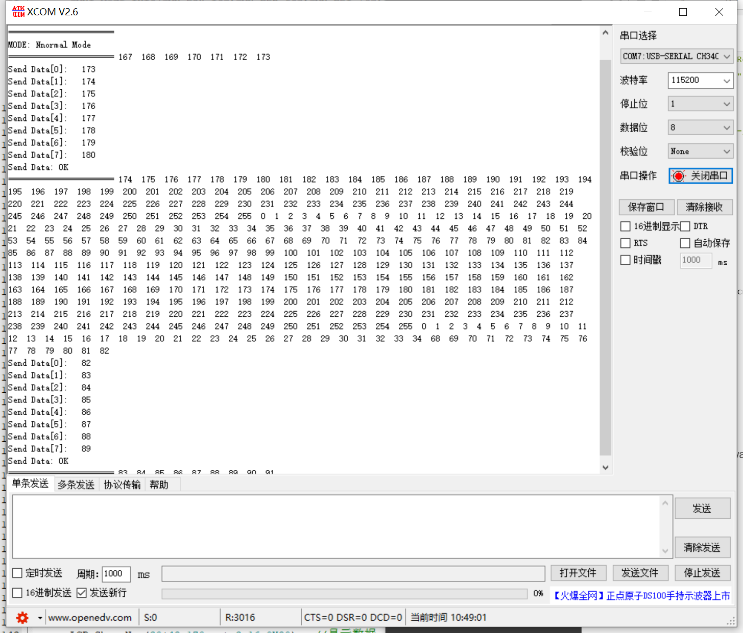
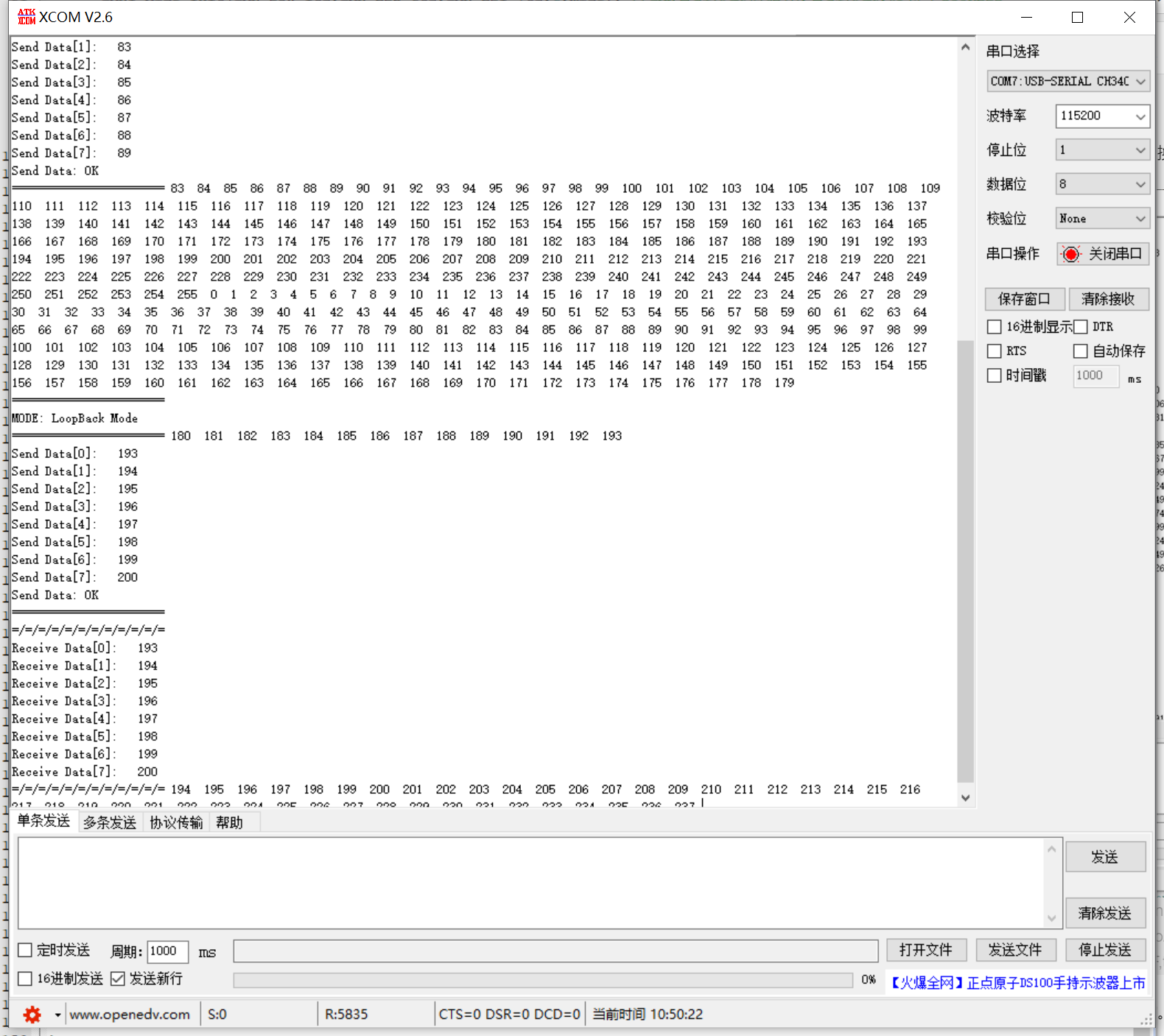
Because it is only sent by a single machine, the information cannot be received. - Loopback mode:
Press the wak-0 counter to count_ Press the up button to switch to the loop mode, and press the key0 button to realize the sending and receiving of primary data, as shown in the figure below.