catalogue
1, Content discussed in this paper
4, Modbus RTU communication protocol
6, Complete Modbus logic function
1, Content discussed in this paper
This paper briefly introduces the Modbus communication protocol, realizes the Modbus Protocol on STM32, and verifies the correctness of the program through joint debugging with Modbus Poll (a MODBUS host computer tool).
2, Tools and source code
Download address of tools and source code: https://gitee.com/xiaowen_git/modbus
3, Modbus overview
Modbus is master-slave communication. There is only one master on a bus, but there can be multiple slaves (this is similar to the communication mode of IIC). In short, that is, the host asks and the slave answers. What are you asking? Two questions are mainly asked -- what is the value of the slave's register (coil), and the master asks the slave to modify the value of the register (coil) and answer.
Modbus can also be subdivided into many protocols, but there are mainly three:
1. (the equipment must have RTU protocol! This is specified in Modbus protocol, and the default mode must be RTU)
2. Modbus ASCII (human readable, verbose representation)
3. Modbus TCP (Ethernet as medium)
In fact, in essence, these three are similar. As long as you master one, you can easily master the other two. This paper explains the Modbus RTU protocol, which is the most commonly used protocol.
4, Modbus RTU communication protocol
Combined with the above, let's understand the Modbus communication protocol. We can understand the communication process as which slave the host calls, what to do and how to do. Finally, the host checks whether its description is correct. There are four steps in total, that is, each communication needs to include these four steps, and each communication needs to send a frame structure. Therefore, there is frame structure = address + function code + data + CRC verification. The address is equivalent to which slave, the function code is what to do, and the data is how to do it. Finally, a CRC check is performed to ensure that the data is correct. It refers to the address: the effective range of the address is 1-247. For other special purposes, for example, 255 is the broadcast address (the broadcast address is to answer all addresses. Normally, it needs the same addresses of the two devices to query and reply). Moreover, RTU has no frame header and tail, so it is clear in the protocol.
There are many function codes, but the most important ones are 01, 06 and 16, and the software Modbus Poll mainly uses these function codes to master these three function codes, and the use of other codes is also similar.
Next, let's understand the differences between the three function codes: function code 01 is a query register, function code 06 modifies a single register, and function code 16 modifies multiple consecutive registers.
Let's understand it directly.
① function code 01 actual combat:
Host sending: 01 03 00 00 01 84 0A
Slave reply: 01 03 02 01 02 35 15
Resolution:

/*Host send resolution*/

01-address

03-Function code,Representative query function,Other functions will be discussed later

00 00-Represents the starting register address of the query.Description from 0 x0000 Start query.

(Here we need to explain the following,Modbus Store data in registers,The values of different variables are obtained by querying registers,A register address corresponds to 2 bytes of data;)

00 01-Represents that a register was queried.Combined with the previous 00,It means to query 1 register value starting from 0;

84 0A-Cyclic redundancy check,yes modbus Check formula for,From the first byte to the front of 84;

(Novices here may not understand,This verification is a means to ensure that there is no error in the data transmission process,This verification formula is different for different protocols,Just understand this is enough,How exactly,The results can be obtained directly from the output data,Address is:http://www.ip33.com/crc.html)

/*Slave reply analysis*/

01-address

03-Function code

02-Represents the number of bytes of subsequent data,Because it says,A register has 2 bytes,So the number of subsequent bytes must be 2*Number of registers queried;

01 02-The value of the register is 0 x0102,Combined with the data sent,01 The value of this register is 0 x0102

35 15-Cyclic redundancy check
② function code 06 actual combat:
Host send: 01 06 00 00 12 34 84 BD
Slave reply: 01 06 00 00 12 34 84 BD
Resolution:

/* Host send resolution */

01-Address of host to check

06-Function code,Represents the function of modifying a single register

00 00-Represents the modified start register address.Description from 0 x0000 start.

12 34-The value representing the modification is 0 x12 34.Combined with the previous 00,This means that the value of register No. 0 is modified to 0 x1234;

84 BD -Cyclic redundancy check,yes Modbus Check formula for,From the first byte to the front of 84;


/*Slave reply analysis*/

01-Address returned from slave,This means that this is the slave of the host

06-Function code,Represents the function of modifying a single register;

00 00-Represents the modified start register address.The description is 0 x0000.

12 34-The value representing the modification is 0 x1234.Combined with the previous 00,This means that the value of register No. 0 is modified to 0 x1234;

84 BD -Cyclic redundancy check,yes Modbus Check formula for,From the first byte to the front of 84;
③ function code 16 actual combat:
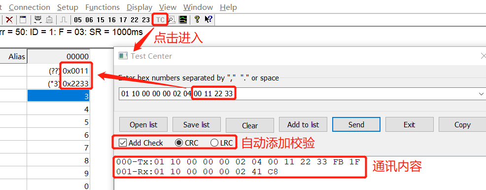
Host sending: 01 10 00 00 02 04 00 11 22 33 FB 1F
Slave reply: 01 10 00 00 02 41 C8
Resolution:

/*Host send resolution*/

01-Host address to check

10-Function code,0x10=16D Represents the function of modifying multiple registers;

00 00-Represents the modified start register address.Description from 0 x0000 start.

00 02-Represents the number of registers modified, starting at 0 x06 The changes are different;

04 -Indicates the total number of bytes modified. Since 2 registers are modified, the data should have 4 bytes;

00 11-Indicates the modified value. In combination with the above, the value of the first register is modified to 0 from the 0000 register x0011,Is to change the 0000 register to 0 x0011;

22 33-Indicates the modified value. Combined with the above, it is to modify the value of the second register from the 0000 register to 0 x22 33,Is to change the 0001 register to 0 x2233;

FB 1F -Cyclic redundancy check,yes Modbus Check formula for,From the first byte to 22;


/*Slave reply analysis*/

01-Address returned from slave,This means that this is the slave of the host

10-Function code

00 00-Represents the modified start register address.The description is 0 x0000.

00 02-Represents the number of modified registers. It's enough to reply for so long. It's enough for the slave to tell the host which registers you modified;

41 C8-Cyclic redundancy check;
5, Complete Modbus I / O code
We use the warship development board of punctual atom, the program template is developed based on the "Experiment 8 timer interrupt experiment (HAL Library)" of punctual atom, and the serial port (USART1) is used as the medium to communicate with the host computer Modbus Poll.
Let's talk about the program of the output part first. This is the simplest. Just call the function of HAL library directly. The code is as follows:
/* Send data function, buff refers to the sent content, and len refers to the number of bytes sent */

void modbus_send_data(u8 *buff,u8 len)

{

    HAL_UART_Transmit(&UART1_Handler,(uint8_t*)buff,len,1000); //send data

    while(__HAL_UART_GET_FLAG(&UART1_Handler,UART_FLAG_TC)!=SET);//Wait for sending to end

}
Then in the input part, I don't know that the reader can't remember the sentence "as the judgment basis for the end of a frame", so how to calculate the byte time? If the baud rate is 9600, it means that 9600 bits of data can be transmitted in one second. The commonly used format in the industry is 8-bit data, no check bit, 1-bit stop bit, plus a necessary 1-bit start bit, then the serial port data of one byte is 10 bits in total. Therefore, the time of each byte is 1 / (9600 / 10) seconds, that is, 1.04ms. If the time interval between two frames is greater than 3.5 bytes, the interval time can be set to 4ms.
In the program, we define a variable modbus_time as the flag bit of interval time, MODBUS_ Put time into the timer interrupt service function (cycle: 1ms) and let it increase the value all the time. In the serial port interrupt function, as long as 1Byte message is received, MODBUS will be_ Time is cleared when MODBUS_ When the time is greater than 4 (the byte interval is 4ms) and the serial port has received data but has not received new bytes, it is considered that the data reception of a frame structure is completed.
Take chestnuts for example. There are 01 02 03 data to be sent. When data 01 is sent, the serial port interrupt clears modbus_time, modbus_time=0, and then after 1.04 seconds, data 02 is sent. At this time, modbus_time=1, but the serial port interrupt clears modbus_time, modbus_time becomes 0 again, and then after 1.04 seconds, data 03 is sent. At this time, modbus_time=1, but the serial port interrupt clears modbus_time, modbus_time becomes 0 again, and finally no data is sent. At this time, MODBUS_ When the time is greater than 4 (the byte interval is 4ms) and the serial port has received data but has not received new bytes, it is considered that the data reception of a frame structure is completed.
In addition, we need to modify the serial port interrupt service function to mark the reception status USART_ RX_ The reception completion flag bit15 of sta is masked (because the original routine of punctual atom is that the serial port receives 0x0d and 0x0a, indicating that the complete serial port data is received), and then the reception status is marked USART_ RX_ The reception completion flag bit15 of sta is written in the timer interrupt function as the Modbus reception completion flag bit. The code is as follows
void HAL_UART_RxCpltCallback(UART_HandleTypeDef *huart)

{

       if(huart->Instance==USART1)//If serial port 1

       {

              if((USART_RX_STA&0x8000)==0)//Reception incomplete

              {

//If (usart_rx_sta & 0x4000) / / 0x0d received

//                  {

//                         if(aRxBuffer[0]!=0x0a)USART_RX_STA=0;// Receive error, restart

//                         else USART_RX_STA|=0x8000; / / reception completed

//                  }

//else / / 0X0D has not been received yet

//                  {

//                         if(aRxBuffer[0]==0x0d)USART_RX_STA|=0x4000;

//                         else

//                         {

                                   USART_RX_BUF[USART_RX_STA&0X3FFF]=aRxBuffer[0] ;

                                   USART_RX_STA++;

                             modbus_time = 0;

                                   if(USART_RX_STA>(USART_REC_LEN-1))USART_RX_STA=0;//Error receiving data, restart receiving

//                         }

//                  }

              }


       }

}
//Callback function, timer interrupt service function call
void HAL_TIM_PeriodElapsedCallback(TIM_HandleTypeDef *htim)
{
if(htim==(&TIM3_Handler))
{
modbus_time++;
if((modbus_time>4) &&((modbus_time & 0x3fff)!=0))
{
USART_RX_STA|=0x8000;
}
}
}6, Complete Modbus logic function
This part tests the foundation of C language. As long as you know the Modbus RTU protocol and have a solid foundation of C language, I believe readers can do it themselves. The detailed part looks at the author's source code implementation.
7, Testing and verification
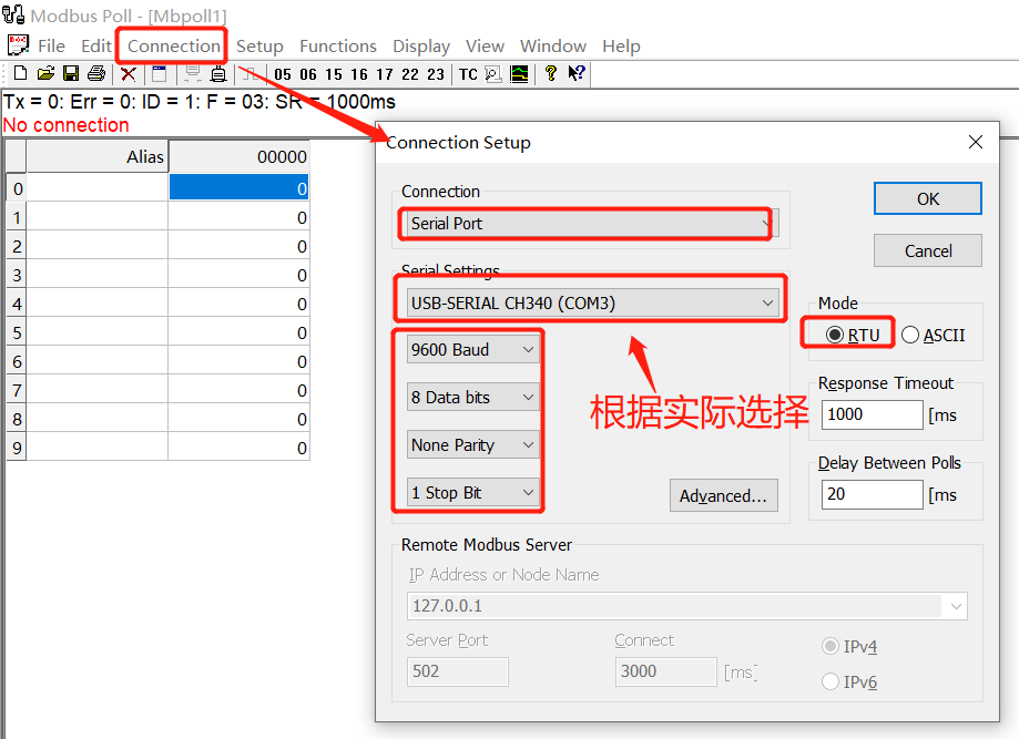
Open the upper computer Modbus Poll, and then connect the upper computer to the board according to the settings shown in the figure below.
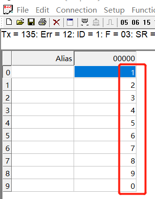
After the connection is successful, the reader will find that the values of 10 registers will change. These ten values are the register values initially set by the program. See the figure below.
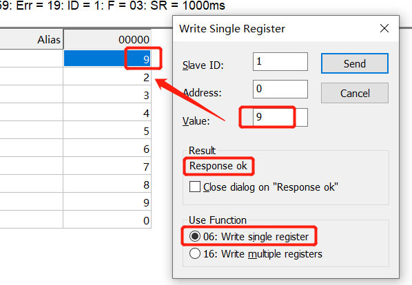
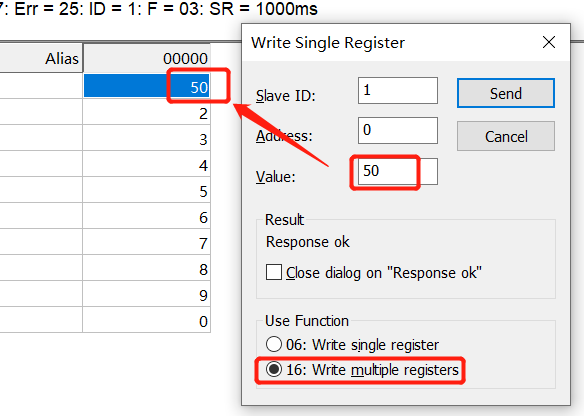
Then we double-click the value in the figure above to enter the interface of quick modification of register value. Then you can test function code 06 and function code 16. The test results are as follows:
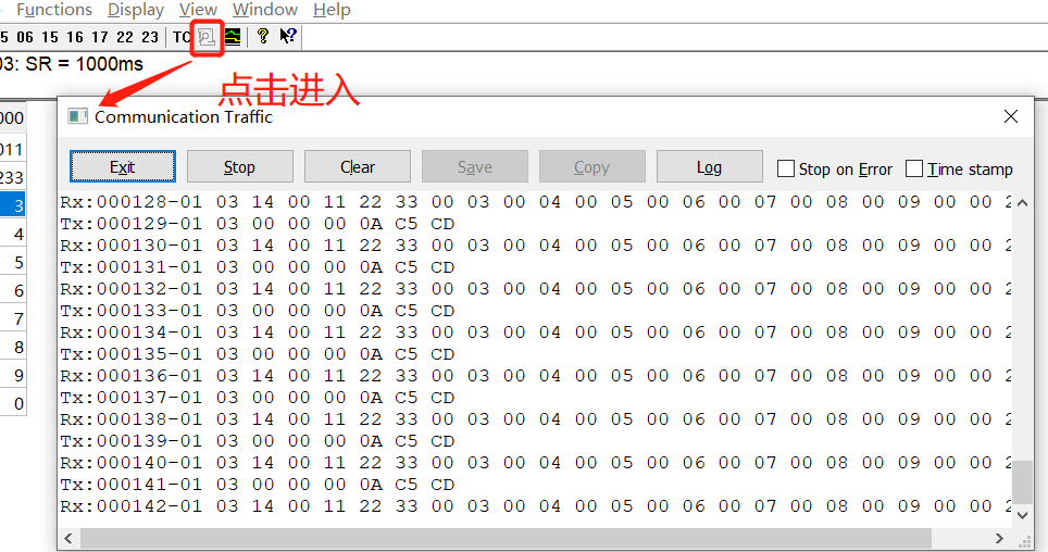
In addition, click "TC" on the right to customize the write data. We can write the data of the tutorial into the test to get the results shown in the figure below. In addition, click the similar search button to view the contents of the current sent message and received message (which can be used in combination with the quick modify register value interface).