preface:
This series of tutorials will explain the principle of corresponding peripherals, HAL library and STM32CubeMX together, so that you can learn to use each module more quickly
Tools used:
1. Chip: STM32F407ZET6/ STM32F103ZET6
2. STM32CubeMx software
3. IDE: MDK keil software
4. STM32F1xx/STM32F4xxHAL Library
Knowledge summary:
Through this blog, you will learn:
RTC clock principle
STM32CubeMX create RTC routine
HAL timer RTC function library
PS: for the RTC explanation here, we only talk about the principle, not the register. If you want to see the register of RTC, please see this article
[STM32] RTC real-time clock, detailed steps, understand RTC in one article
What is RTC
RTC (Real Time Clock): real time clock
RTC is an independent timer. RTC module has a counter that counts continuously. Under the corresponding software configuration, it can provide the function of clock and calendar. Modifying the value of the counter can reset the current time and date. RTC also includes an automatic wake-up unit for managing low-power mode.
In case of power failure, RTC can still operate independently. As long as the standby power supply of the chip is always powered, the time on RTC will go all the time.
RTC is essentially a timer that continues to run after power failure. From the perspective of timer, compared with the general timer TIM peripheral, its function is very simple, with only timing function (it can also trigger interrupt). But its advanced point out that it can still operate normally after power failure.
Two 32-bit registers contain seconds, minutes, hours (12 or 24-hour system), day of the week, date, month, and year in binary decimal format (BCD). In addition, sub second values in binary format can be provided. The system can automatically compensate the number of days in the month to 28, 29 (leap year), 30 and 31 days.
After power on reset, all RTC registers will be protected to prevent possible abnormal write access.
Regardless of the device state (operation mode, low power consumption mode or reset state), the RTC will not stop working as long as the power supply voltage remains within the operating range.
RCT features:
● programmable pre frequency division coefficient: the high frequency division coefficient is 220.
● 32-bit programmable counter, which can be used for measurement in a long period of time.
● two separate clocks: PCLK1 and RTC clocks for APB1 interface (the frequency of RTC clock must be less than more than one fourth of that of PCLK1).
● the following three RTC clock sources can be selected:
● HSE clock divided by 128;
● LSE oscillator clock;
● LSI oscillator clock
● 2 independent reset types:
● APB1 interface is reset by the system;
● RTC core (prescaler, alarm clock, counter and divider) can only be reset by the backup domain
● 3 special maskable interrupts:
● 1. Alarm clock interrupt is used to generate a software programmable alarm clock interrupt.
● 2. Second interrupt is used to generate a programmable periodic interrupt signal (up to 1 second long).
● 3. Overflow interrupt indicates that the internal programmable counter overflows and returns to 0.
RTC clock source:
Three different clock sources can be used to drive the system clock (SYSCLK):
● HSI oscillator clock
● HSE oscillator clock
● PLL clock
These devices have the following two secondary clock sources:
● 40kHz low speed internal RC, which can be used to drive independent watchdog and drive RTC through program selection. RTC is used to automatically wake up the system from shutdown / standby mode.
● 32.768kHz low speed external crystal can also be used to drive RTC(RTCCLK) through program selection.
RTC principle block diagram
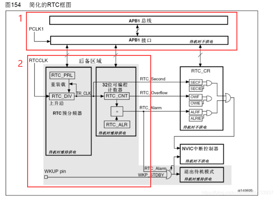
The block diagram of RTC clock is still relatively simple. Here we divide it into two parts:
APB1 interface: used to connect with APB1 bus. This unit also contains a set of 16 bit registers, which can be read and written through APB1 bus. APB1 interface is driven by APB1 bus clock and used to connect with APB1 bus.
The relevant registers (prescaled value, counter value and alarm clock value) of RTC can be accessed through APB1 interface.
RTC core interface: it is composed of a group of programmable counters and is divided into} two main modules.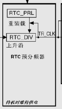 g)
g)
The first module is the prescaler module of RTC, which can be programmed to generate 1-second RTC time reference TR_CLK. The prescaler module of RTC includes a 20 bit programmable frequency divider (RTC prescaler). If in RTC_ If the corresponding allowable bit is set in the CR register, it is set in each tr_ In CLK cycle, RTC generates an interrupt (second interrupt).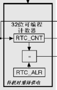
The second module is a 32-bit programmable counter (RTC_CNT), which can be initialized to the current system time. A 32-bit clock counter, calculated by seconds, can record 4294967296 seconds, about 136 years. As a general application, this is enough.
Specific process of RTC:
RTCCLK passes RTC_DIV prescaler, RTC_PRL sets the prescaled coefficient, and then TR is obtained_ For CLK clock signal, we generally set its cycle to 1s, RTC_CNT counter counts. If 1970 is set as the time starting point is 0s, the current time is calculated by the seconds of the current time. RTC_ALR is to set the alarm time, RTC_CNT count to RTC_ALR will generate count interrupt,
- RTC_Second is the second interrupt, which is used to refresh the time,
- RTC_Overflow is an overflow interrupt.
- RTC Alarm control switch
RTC clock selection
When using HSE frequency division clock or LSI, both clock sources will be affected when the main power supply VDD is powered off, so it is impossible to ensure the normal operation of RTC Therefore, RTC generally uses low-speed external clock LSE, and the frequency is 32.768KHz commonly used in real-time clock module. Because 32768 = 2 ^ 15, frequency division is easy to realize, so it is widely used in RTC module (when the main power supply VDD is valid (standby), RTC can also configure alarm events to make STM32 exit the standby mode)
RTC reset process
Except RTC_PRL,RTC_ALR,RTC_CNT and RTC_ Except div register, all system registers are asynchronously reset by system reset or power reset.
RTC_PRL,RTC_ALR,RTC_CNT and RTC_DIV register can only be reset by backup domain reset signal.
After the system is reset, access to the backup register and RCT is prohibited to prevent accidental write operations to the guard area (BKP)
RTC interrupt
Second interrupt:
Here, the clock comes with a second interrupt. Every time the count is increased by one, a second interrupt will be triggered,. Note that the second interrupt mentioned here is not necessarily a second, but a "second" time determined by RTC clock source and frequency division value. Of course, it can be interrupted once a second. We achieve the effect of time synchronization by writing the function of update time into the second interrupt
Alarm clock interrupt:
Alarm clock interrupt is to set a preset value and count how many times it is added to trigger an alarm clock interrupt
CubeMX configuration RTC
Project creation
1 set RCC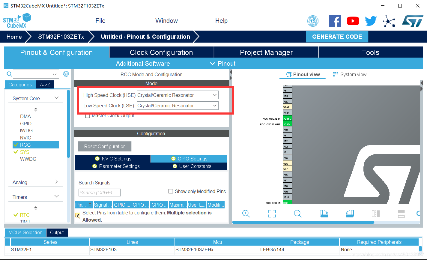
- Set the high-speed external clock and select the external clock source
- Enable external crystal oscillator LSE
When the RTC equipment uses the HSE frequency division clock or LSI because of its unique operation mode (i.e. it still operates after power failure), both clock sources will be affected when the main power supply VDD is powered down, and the resource consumption is too large to eat a small button battery. There is no guarantee that RTC will work properly Therefore, RTC generally uses low-speed external clock LSE
2. Configure RTC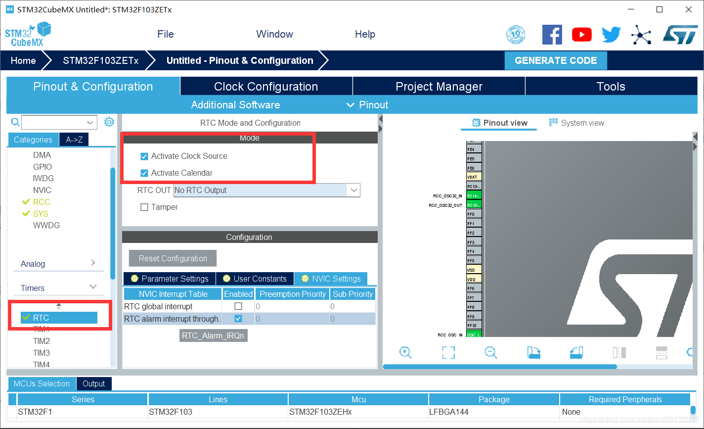
- Activate Clock Source
- Activate calendar activate calendar
Both of these points have obvious effects. First, enable the clock source, and then enable the RTC calendar
- RTC_OUT: Not RTC_OUT
- Tamper: ×
The first is whether to enable the output of the corrected second pulse clock on the {tamper (PC13) pin,
Second: RTC intrusion detection verification function
RTC verification function enables intrusion detection function. The RTC clock is output to the intrusion detection pin TAMPER through 64 frequency division
When the signal on the TAMPER pin changes from 0 to 1 or from 1 to 0 (depending on the TPAL bit of the backup control register BKP_CR), an intrusion detection event is generated. The intrusion detection event clears the contents of all data backup registers.
- That is, the first enable tamper (PC13) pin is output as a clock pulse
- The second is to enable the tamper (PC13) pin as an intrusion detection function
The following are two RTC interrupts:
- RTC global interrupt_ IRQHandler()
- Alarm clock interrupt function RTCAlarm_IRQHandler()
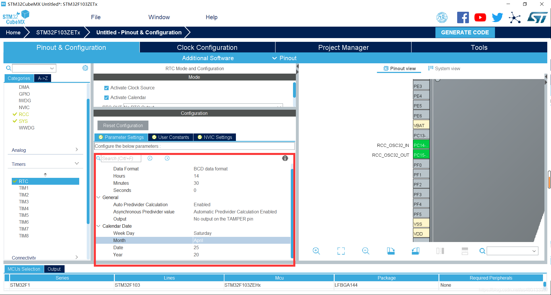
The time set here is 2020 / 04 / 25 13:30:00
- Data Format: date format
Binary data format hex
BCD data format BCD code base
If automatic configuration is used, BCD data format must be used for initialization time, because there is a bug in the library function. If Binary data format is used, month configuration will make an error. For example, in November, RTC will be assigned during configuration_ MONTH_ November, and the macro definition value is 0x11, that is, its decimal value is 17
-
Hours: hours
-
Minutes: minutes
-
Seconds: seconds
-
Week Day:
-
Month month
-
Date: Date
-
Year: year
3 enable serial port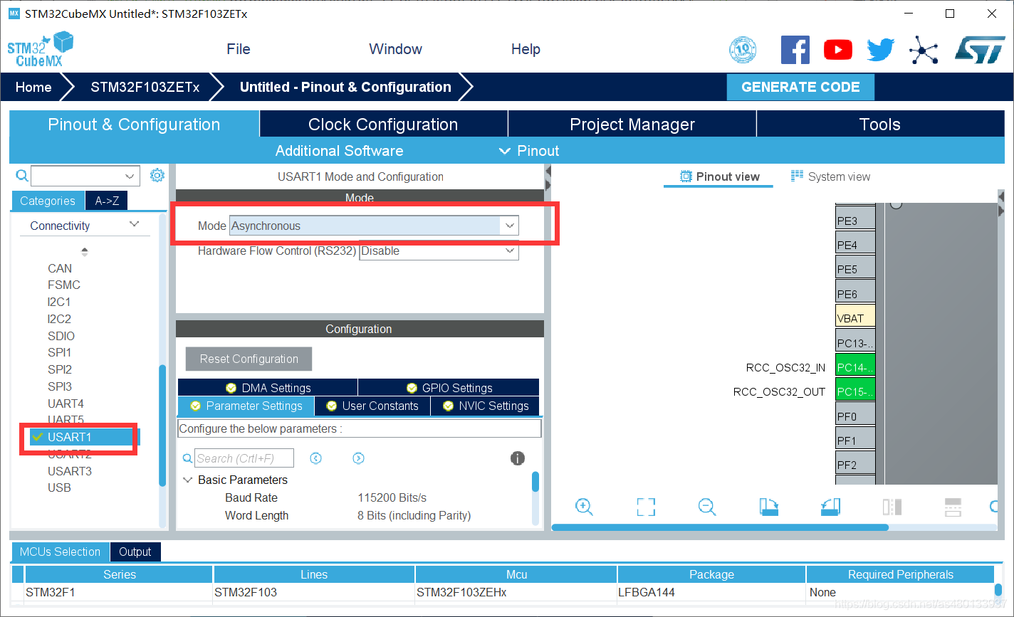
Enable the serial port because the date is sent to the upper computer
4 clock source setting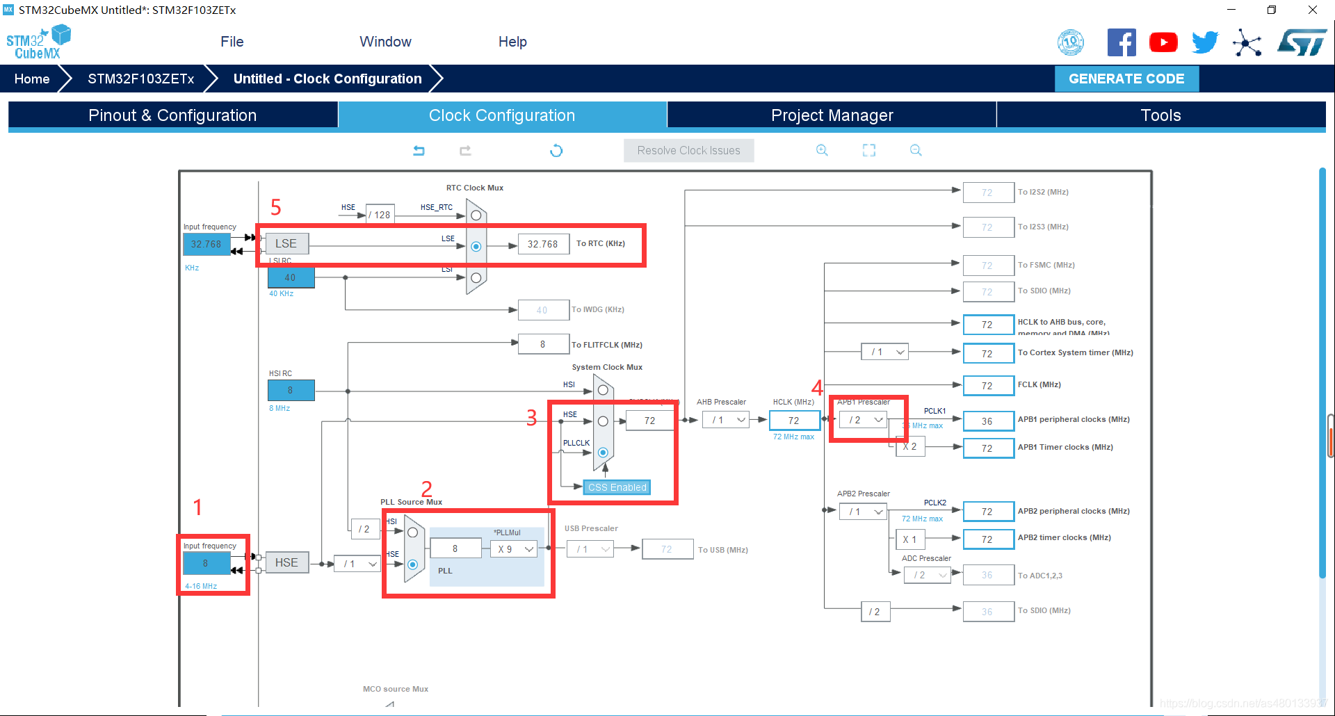
My external crystal oscillator is 8MHz
- 1. Select the external clock HSE 8MHz
- 2PLL PLL frequency doubling 9 times
- 3. PLL is selected as the system clock source
- 4 set APB1 frequency divider to / 2
- 5 enable CSS monitor clock
- 6 set RTC clock to LSE
32 clock tree block diagram, if you don't understand, please read it Detailed explanation of [STM32] system clock RCC (super detailed, super comprehensive)
5 project file settings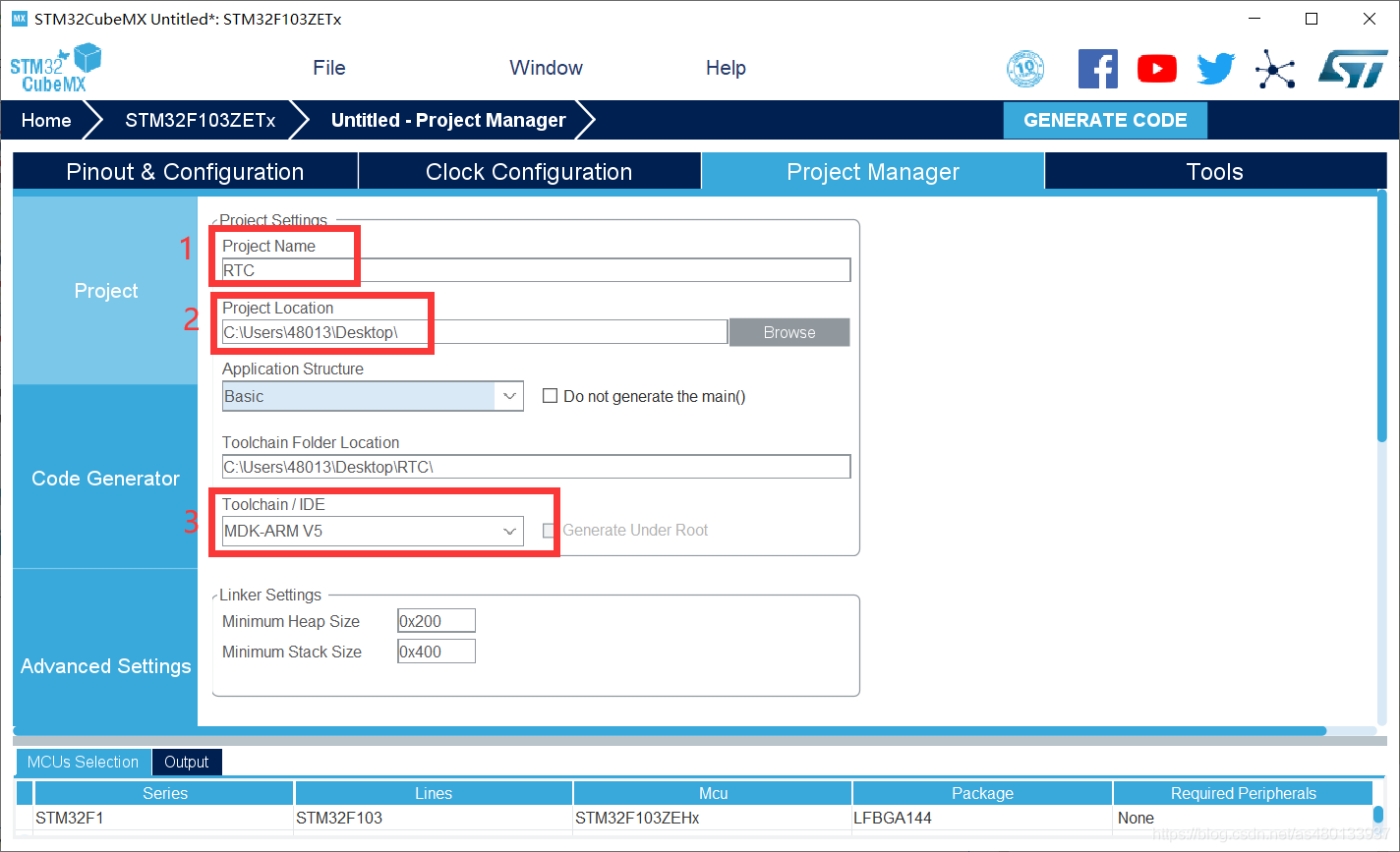
- 1 set project name
- 2 set storage path
- 3 select the IDE to use
6 create project files
Then click GENERATE CODE to create the project
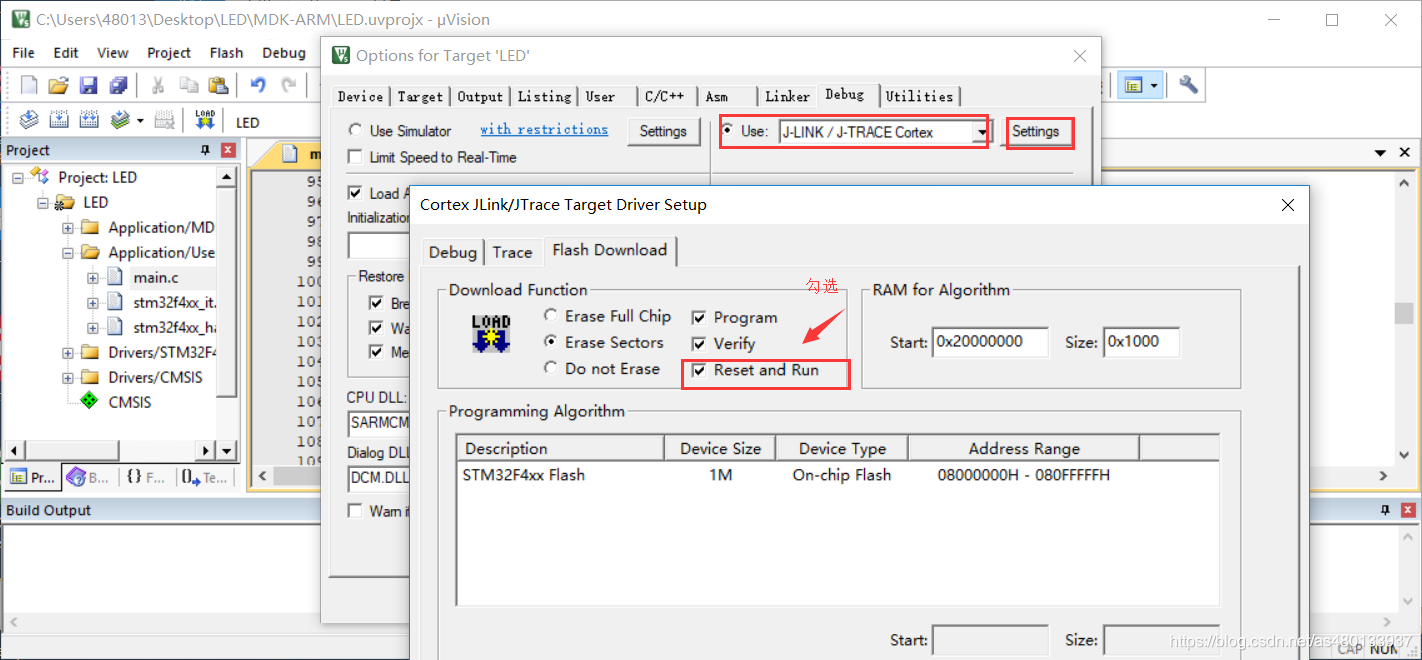
Configure download tool
All configurations of the new project are default. We need to select the download mode by ourselves, and check the reset operation after downloading
RTC_HAL library function
/*Set system time*/
HAL_StatusTypeDef HAL_RTC_SetTime(RTC_HandleTypeDef *hrtc, RTC_TimeTypeDef *sTime, uint32_t Format)
/*Read system time*/
HAL_StatusTypeDef HAL_RTC_GetTime(RTC_HandleTypeDef *hrtc, RTC_TimeTypeDef *sTime, uint32_t Format)
/*Set system date*/
HAL_StatusTypeDef HAL_RTC_SetDate(RTC_HandleTypeDef *hrtc, RTC_DateTypeDef *sDate, uint32_t Format)
/*Read system date*/
HAL_StatusTypeDef HAL_RTC_GetDate(RTC_HandleTypeDef *hrtc, RTC_DateTypeDef *sDate, uint32_t Format)
/*Start alarm function*/
HAL_StatusTypeDef HAL_RTC_SetAlarm(RTC_HandleTypeDef *hrtc, RTC_AlarmTypeDef *sAlarm, uint32_t Format)
/*Set alarm interrupt*/
HAL_StatusTypeDef HAL_RTC_SetAlarm_IT(RTC_HandleTypeDef *hrtc, RTC_AlarmTypeDef *sAlarm, uint32_t Format)
/*Alarm time callback function*/
__weak void HAL_RTC_AlarmAEventCallback(RTC_HandleTypeDef *hrtc)
/*Write to backup memory*/
void HAL_RTCEx_BKUPWrite(RTC_HandleTypeDef *hrtc, uint32_t BackupRegister, uint32_t Data)
/*Read backup memory*/
uint32_t HAL_RTCEx_BKUPRead(RTC_HandleTypeDef *hrtc, uint32_t BackupRegister
We can see that the first four functions are
- Set system time: HAL_RTC_SetTime();
- Read system time: HAL_RTC_GetTime();
- Set system date: HAL_RTC_SetDate();
- Read system date: HAL_RTC_GetDate();
Because the time and date of the system have been set at the beginning, we only use two reading functions here
Read system time function
/*Read system time*/
HAL_StatusTypeDef HAL_RTC_GetTime(RTC_HandleTypeDef *hrtc, RTC_TimeTypeDef *sTime, uint32_t Format)
Function: obtain the time of RTC clock
Parameters:
-
*Parameter example of hrtc RTC structure: &hi2c2
-
RTC_TimeTypeDef * sTime: gets the structure of RTC time,
-
Format: gets the format of the time
RTC_FORMAT_BIN uses hexadecimal
RTC_FORMAT_BCD uses BCD base
Read system date function
/*Read system date*/
HAL_StatusTypeDef HAL_RTC_GetDate(RTC_HandleTypeDef *hrtc, RTC_DateTypeDef *sDate, uint32_t Format)
- 1
- 2
Function: get the date of RTC clock
Parameters:
-
*Parameter example of hrtc RTC structure: &hi2c2
-
RTC_DateTypeDef * sTime: gets the structure of RTC date,
-
Format: gets the format of the date
RTC_FORMAT_BIN uses hexadecimal
RTC_FORMAT_BCD uses BCD base
In stm32f1xx_hal_rtc.h header file, RTC can be found_ TimeTypeDef,RTC_DateTypeDef is a member variable of these two structs.
/**
  * @brief  RTC Time structure definition
  */
typedef struct
{
  uint8_t Hours;            /*!< Specifies the RTC Time Hour.
                                 This parameter must be a number between Min_Data = 0 and Max_Data = 23 */

  uint8_t Minutes;          /*!< Specifies the RTC Time Minutes.
                                 This parameter must be a number between Min_Data = 0 and Max_Data = 59 */

  uint8_t Seconds;          /*!< Specifies the RTC Time Seconds.
                                 This parameter must be a number between Min_Data = 0 and Max_Data = 59 */

} RTC_TimeTypeDef;- 1
- 2
- 3
- 4
- 5
- 6
- 7
- 8
- 9
- 10
- 11
- 12
- 13
- 14
- 15
/**
  * @brief  RTC Date structure definition
  */
typedef struct
{
  uint8_t WeekDay;  /*!< Specifies the RTC Date WeekDay (not necessary for HAL_RTC_SetDate).
                         This parameter can be a value of @ref RTC_WeekDay_Definitions */

  uint8_t Month;    /*!< Specifies the RTC Date Month (in BCD format).
                         This parameter can be a value of @ref RTC_Month_Date_Definitions */

  uint8_t Date;     /*!< Specifies the RTC Date.
                         This parameter must be a number between Min_Data = 1 and Max_Data = 31 */

  uint8_t Year;     /*!< Specifies the RTC Date Year.
                         This parameter must be a number between Min_Data = 0 and Max_Data = 99 */

} RTC_DateTypeDef;
Program code:
main.c
In main C rewrites the fputc function so that the printf function can be used
#include "stdio.h"


int fputc(int ch,FILE *f){
 uint8_t temp[1]={ch};
 HAL_UART_Transmit(&huart1,temp,1,2);
 return ch;
}
Define two structures to get the date and time:
RTC_DateTypeDef GetData;  //Get date structure

RTC_TimeTypeDef GetTime;   //Get time structure
Add to the while loop:
	  /* Get the RTC current Time */
	  HAL_RTC_GetTime(&hrtc, &GetTime, RTC_FORMAT_BIN);
      /* Get the RTC current Date */
      HAL_RTC_GetDate(&hrtc, &GetData, RTC_FORMAT_BIN);

      /* Display date Format : yy/mm/dd */
      printf("%02d/%02d/%02d\r\n",2000 + GetData.Year, GetData.Month, GetData.Date);
      /* Display time Format : hh:mm:ss */
      printf("%02d:%02d:%02d\r\n",GetTime.Hours, GetTime.Minutes, GetTime.Seconds);

      printf("\r\n");

HAL_Delay(1000);Routine test OK: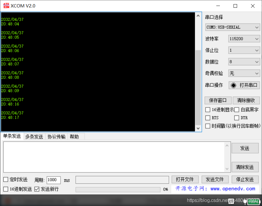
RTC power down reset
However, for the code generated in hal library, the RTC time will be reset every time the power is off, and the time will be reinitialized every time the power is on
Because the HAL library sets a BKP register to hold a flag. Each time the single chip microcomputer starts, it reads this flag and judges whether it is a preset value: if the result is not, initialize the RTC and set the time, and then set the flag as the expected value; If it is the expected value, skip the initialization and time settings and continue with the following procedures
Therefore, we only need to set the flag to the expected value before each power on and RTC initialization
In RTC RTC in C_ Init can be modified as follows:
 void MX_RTC_Init(void)
{

  /* USER CODE BEGIN RTC_Init 0 */
		RTC_TimeTypeDef time;   //Time structure parameters
		RTC_DateTypeDef datebuff;   //Date structure parameters
  /* USER CODE END RTC_Init 0 */

  RTC_TimeTypeDef sTime = {0};
  RTC_DateTypeDef DateToUpdate = {0};

  /* USER CODE BEGIN RTC_Init 1 */
	__HAL_RCC_BKP_CLK_ENABLE();       //Turn on the backup area clock
	__HAL_RCC_PWR_CLK_ENABLE();		  //Turn on the power clock
  /* USER CODE END RTC_Init 1 */
  /**Initialize RTC Only
  */
  hrtc.Instance = RTC;
  hrtc.Init.AsynchPrediv = RTC_AUTO_1_SECOND;
  hrtc.Init.OutPut = RTC_OUTPUTSOURCE_NONE;
  if (HAL_RTC_Init(&hrtc) != HAL_OK)
  {
    Error_Handler();
  }

  /* USER CODE BEGIN Check_RTC_BKUP */
	if(HAL_RTCEx_BKUPRead(&hrtc,RTC_BKP_DR1)!= 0x5051)
	{

  /* USER CODE END Check_RTC_BKUP */

  /**Initialize RTC and set the Time and Date
  */
  sTime.Hours = 0x14;
  sTime.Minutes = 0x30;
  sTime.Seconds = 0x0;

  if (HAL_RTC_SetTime(&hrtc, &sTime, RTC_FORMAT_BCD) != HAL_OK)
  {
    Error_Handler();
  }
  DateToUpdate.WeekDay = RTC_WEEKDAY_SATURDAY;
  DateToUpdate.Month = RTC_MONTH_APRIL;
  DateToUpdate.Date = 0x25;
  DateToUpdate.Year = 0x20;

  if (HAL_RTC_SetDate(&hrtc, &DateToUpdate, RTC_FORMAT_BCD) != HAL_OK)
  {
    Error_Handler();
  }
  /* USER CODE BEGIN RTC_Init 2 */

	__HAL_RTC_SECOND_ENABLE_IT(&hrtc,RTC_IT_SEC);	 //Turn on RTC clock second interrupt
	datebuff = DateToUpdate;  //Copy the date data to the data defined by yourself
	HAL_RTCEx_BKUPWrite(&hrtc, RTC_BKP_DR1, 0x5051);//Writes data to the specified fallback area register
	HAL_RTCEx_BKUPWrite(&hrtc, RTC_BKP_DR2, (uint16_t)datebuff.Year);
	HAL_RTCEx_BKUPWrite(&hrtc, RTC_BKP_DR3, (uint16_t)datebuff.Month);
	HAL_RTCEx_BKUPWrite(&hrtc, RTC_BKP_DR4, (uint16_t)datebuff.Date);
	HAL_RTCEx_BKUPWrite(&hrtc, RTC_BKP_DR5, (uint16_t)datebuff.WeekDay);

  }
	else
	{
		datebuff.Year    = HAL_RTCEx_BKUPRead(&hrtc, RTC_BKP_DR2);
		datebuff.Month   = HAL_RTCEx_BKUPRead(&hrtc, RTC_BKP_DR3);
		datebuff.Date    = HAL_RTCEx_BKUPRead(&hrtc, RTC_BKP_DR4);
		datebuff.WeekDay = HAL_RTCEx_BKUPRead(&hrtc, RTC_BKP_DR5);
		DateToUpdate = datebuff;
		if (HAL_RTC_SetDate(&hrtc, &DateToUpdate, RTC_FORMAT_BIN) != HAL_OK)
		{
			Error_Handler();
		}
		__HAL_RTC_SECOND_ENABLE_IT(&hrtc,RTC_IT_SEC);	 //Turn on RTC clock second interrupt
	}


}