1, Understanding registers
(1) What is a register
Registers are some small storage areas used to store data in the CPU. They are used to temporarily store instructions, data and addresses involved in operations. Is a common sequential logic circuit, but this sequential logic circuit only includes storage circuit. The storage circuit of the register is composed of a latch or trigger. Because a latch or trigger can store a 1-bit binary number, N latches or triggers can form an N-bit register.
(2) What is register mapping
Since the memory itself does not have an address, the process of assigning an address to the memory is called memory mapping. In the memory Block2 area, on-chip peripherals are designed. They take four bytes as a unit, a total of 32bit. Each unit corresponds to different functions. When we control these units, we can drive the peripherals to work. We can find the starting address of each unit, and then access these units through the operation mode of C language pointer. If we access these units through this address every time, it is not only bad memory, but also easy to make mistakes. At this time, we can give an alias to this memory unit in the name of function according to the different functions of each unit, This alias is what we often call a register. The process of aliasing memory units with specific functions that have been assigned addresses is called register mapping.
2, Configure GPIO ports
(1) Configure clock
RCC_APB2PeriphClockCmd(RCC_APB2Periph_GPIOB, ENABLE); //Turn on the clock of the peripheral GPIOB
(2) GPIO initialization structure
The library function provides a structure to configure the input / output mode setting and maximum rate setting of GPIO port
as follows
typedef struct
{
  uint16_t GPIO_Pin;             /*!< Specifies the GPIO pins to be configured.
                                      This parameter can be any value of @ref GPIO_pins_define */

  GPIOSpeed_TypeDef GPIO_Speed;  /*!< Specifies the speed for the selected pins.
                                      This parameter can be a value of @ref GPIOSpeed_TypeDef */

  GPIOMode_TypeDef GPIO_Mode;    /*!< Specifies the operating mode for the selected pins.
                                      This parameter can be a value of @ref GPIOMode_TypeDef */
}GPIO_InitTypeDef;
(3) It is configured as universal push-pull output, and the output speed is 2M
    GPIO_InitTypeDef   GPIO_InitStruct;

	GPIO_InitStruct.GPIO_Mode=GPIO_Mode_Out_PP;  			//The output mode is universal push-pull output
	GPIO_InitStruct.GPIO_Pin=GPIO_Pin_1 ;             //The selected port is GPIO_ Pin_ one
	GPIO_InitStruct.GPIO_Speed=GPIO_Speed_2MHz;				//The output speed is 2M

	GPIO_Init(GPIOB,&GPIO_InitStruct);
3, Simple water lamp design
(1) Code design
main.c
#define RCC_AP2ENR *((unsigned volatile int*)0x40021018)
//----------------GPIOA configuration register------------------------
#define GPIOA_CRH *((unsigned volatile int*)0x40010804)
#define GPIOA_ORD *((unsigned volatile int*)0x4001080C)
//----------------GPIOB configuration register------------------------
#define GPIOB_CRL *((unsigned volatile int*)0x40010C00)
#define GPIOB_ORD *((unsigned volatile int*)0x40010C0C)
//----------------GPIOC configuration register------------------------
#define GPIOC_CRH *((unsigned volatile int*)0x40011004)
#define GPIOC_ORD *((unsigned volatile int*)0x4001100C)
//-------------------Simple delay function-----------------------
void Delay_ms( volatile unsigned int t)
{
unsigned int i;
while(t--)
for (i=0;i<800;i++);
}
//------------------------Main function--------------------------
int main()
{
int j=100;
RCC_AP2ENR|=1<<2; //APB2-GPIOA peripheral clock enable
RCC_AP2ENR|=1<<3; //APB2-GPIOB peripheral clock enable
RCC_AP2ENR|=1<<4; //APB2-GPIOC peripheral clock enable
//These two lines of code can be combined into RCC_ APB2ENR|=1<<3|1<<4;
GPIOA_CRH&=0xFFF0FFFF; //Set bit reset
GPIOA_CRH|=0x00020000; //PA12 push pull output
GPIOA_ORD|=1<<12; //Set the initial light to on
GPIOB_CRL&=0xFFFFFF0F; //Set bit reset
GPIOB_CRL|=0x00000020; //PB1 push pull output
GPIOB_ORD|=1<<1; //Set the initial light to off
GPIOC_CRH&=0xF0FFFFFF; //Set bit reset
GPIOC_CRH|=0x02000000; //PC14 push pull output
GPIOC_ORD|=1<<14; //Set the initial light to off
while(j)
{
GPIOA_ORD=0x1<<12; //PA12 high level
Delay_ms(3000000);
GPIOA_ORD=0x0<<12; //PA12 low level
Delay_ms(3000000);
GPIOB_ORD=0x1<<1; //PB1 high level
Delay_ms(3000000);
GPIOB_ORD=0x0<<1; //PB1 low level
Delay_ms(3000000);
GPIOC_ORD=0x1<<14; //PC14 high level
Delay_ms(3000000);
GPIOC_ORD=0x0<<14; //PC14 low level
Delay_ms(3000000);
}
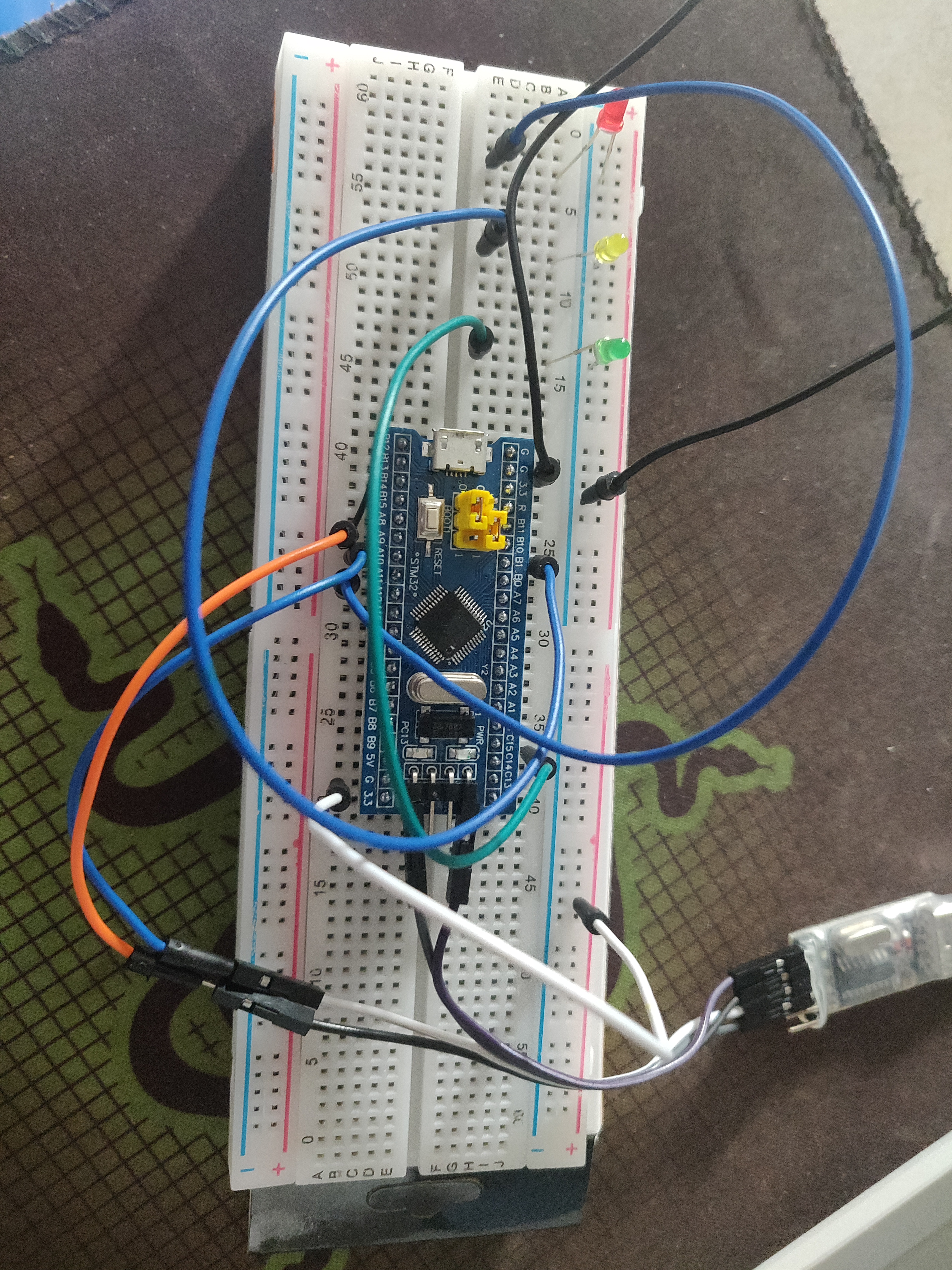
}(2) Development board circuit connection
- GND of USB to TTL module is connected to the ground of the smallest system board
- 3v3 of USB to TTL module connected to the minimum system board 3v3
- TXD of USB to TTL module is connected to PA10 of the smallest system board
- RXD of USB to TTL module is connected to PA9 of the smallest system board
- PA12, PB1 and PC14 of the smallest system board are respectively connected to the positive pole of red, yellow and green LED lamps, and the negative pole of LED lamps is grounded.
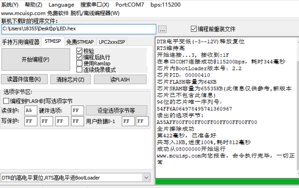
(3) Burning program
 The following is the successful gif picture of running water lamp
4, References
STM32 register water lamp_ zxp_124 blog - CSDN blog
stm32 fancy point water lamp_ Xinghe blog - CSDN blog
stm32 from address to register_ Geekyatao CSDN blog_ stm32 register address