STM32 SPI obtains the angle data of magnetic angle sensor AS5048A
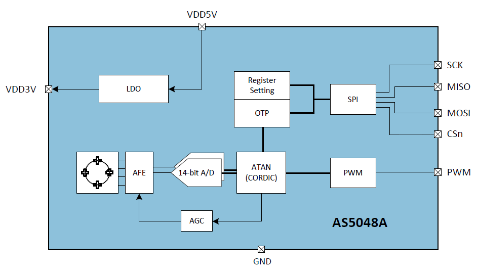
AS5048A is a 14 bit precision magnetic angle detection sensor with SPI interface. In fact, the stability accuracy is only 12 bits, that is, when the detection environment is static, the last two bits of data output are changing and not constant. AS5048A can be used for rotation angle detection, such as rotary encoder, especially for Z-axis rotation detection, such as PTZ angle detection.
The following are the official modules:
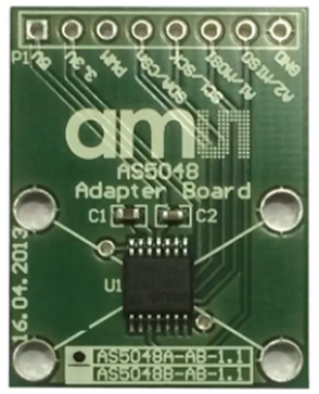
Because AS5048A can output angle data through SPI or PWM line, the third-party module can output PWM and SPI separately. Only the angle output mode of SPI is introduced here.
Detection principle
The following is the angle detection principle of the magnetic angle sensor, which requires the cooperation of the magnetic plate of the semicircular magnetic pole. When the magnetic plate rotates, AS5048A detects the change of the magnetic line of force to obtain the angle information.
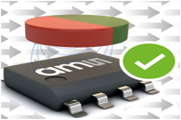
AS5048A is a 360 degree detection sensor, and the user can set the 0 angle position. The advantage is that the angle is directly output without the conversion from angular velocity to angle, and the test shows that there is no zero drift during long-time operation.
SPI protocol
AS5048A adopts 16 bit SPI access format, and the sending format of operation address setting command is as follows:
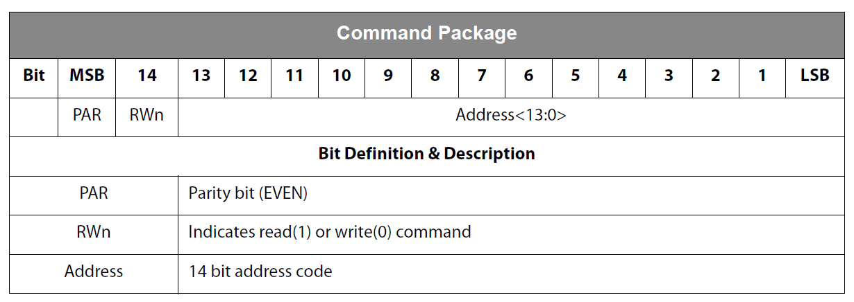
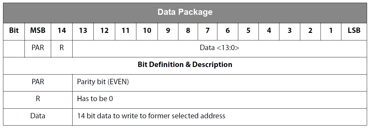
The write data format is as follows:
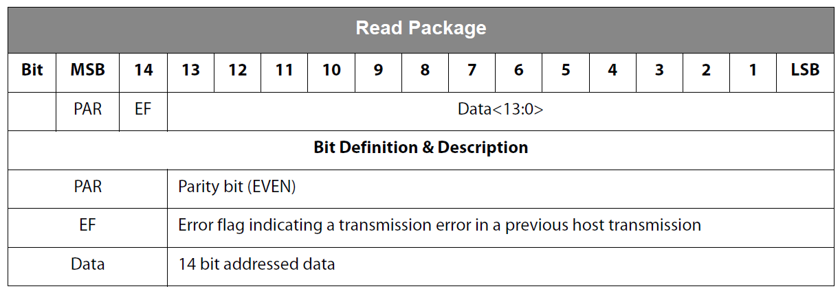
The read data format is as follows:
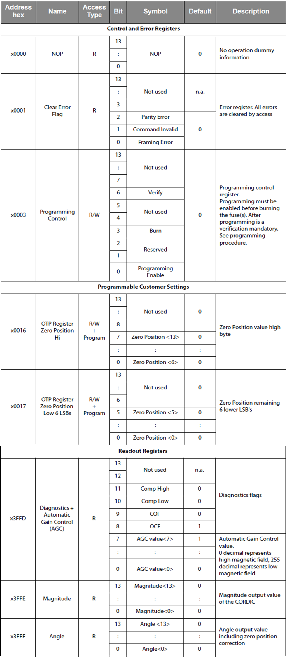
The functions of AS5048A internal register are as follows:
Reading angle operation mode
According to the timing requirements, the operation mode of reading angle can be:
- Clear error register instruction
- Empty operation instruction
- Read angle command
- Empty operation instruction
Therefore, SPI instructions will be sent four times. Due to the transmission and reception full duplex mode, the data received in the last empty operation instruction cycle includes angle data.
Angle data processing
There are two processing methods for angle data:
- Set the zero position, and then directly use the read angle data
- The zero position is not set. When STM32 chip is powered on, first read the current position data as "zero", and then carry out algorithm processing.
The following routine is implemented in the second way.
STM32 routine
The routine adopts STM32F103ZET6 chip development board and stm32subeide development environment.
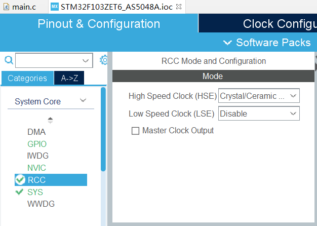
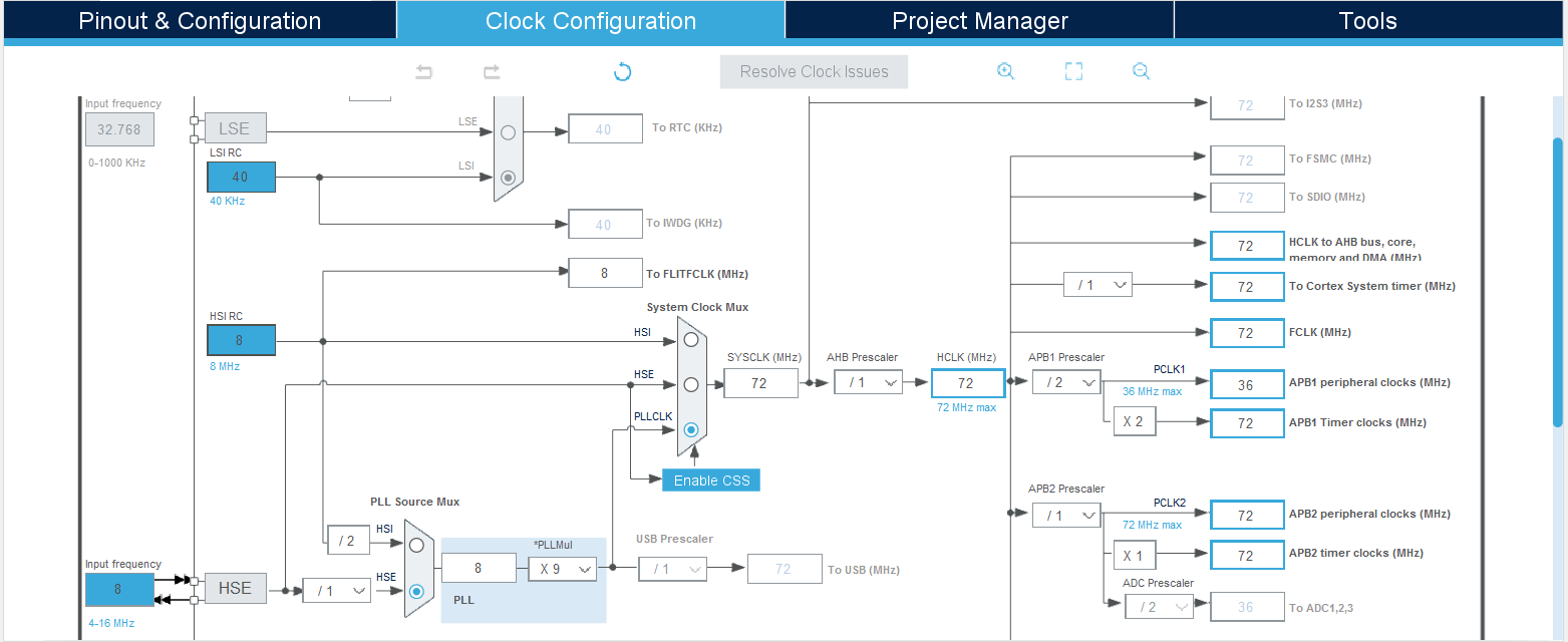
Firstly, establish the project and set the clock to double the external 8MHz clock to the system clock.
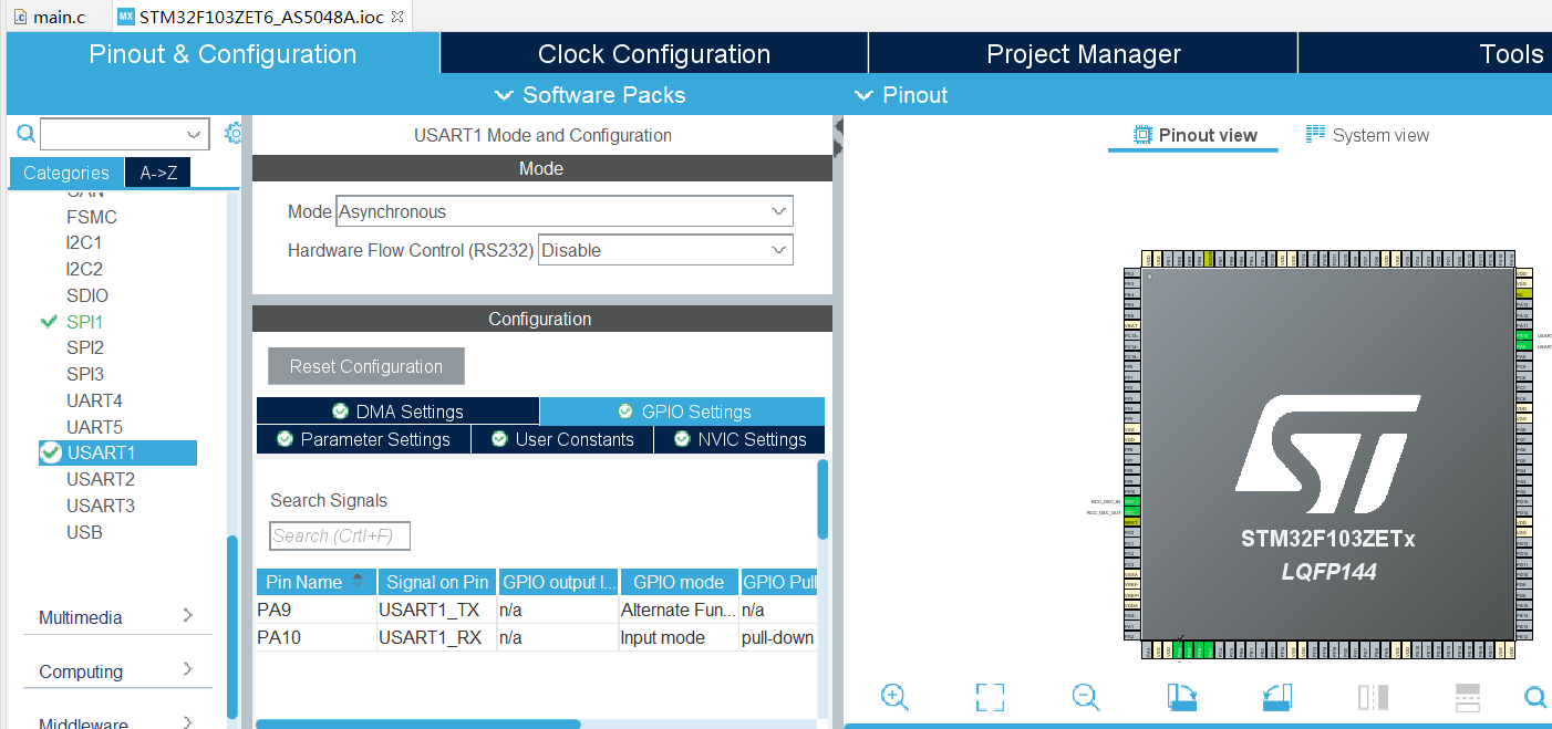
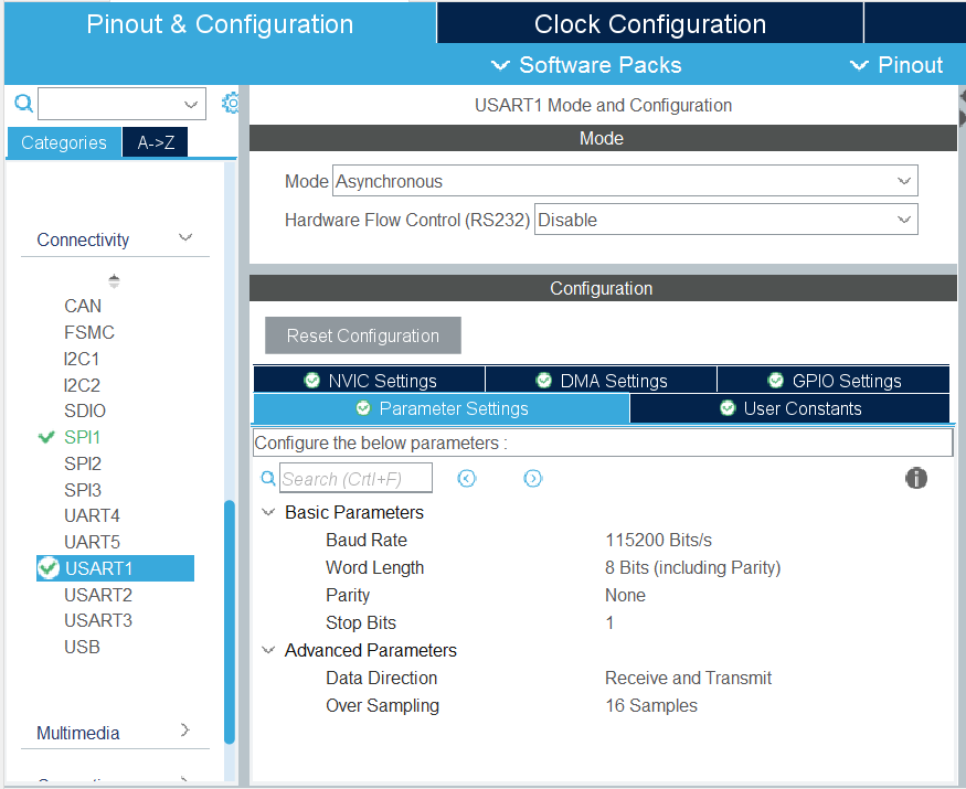
Use USART1 asynchronous serial port to output data, and configure USART1 to 115200 baud rate:
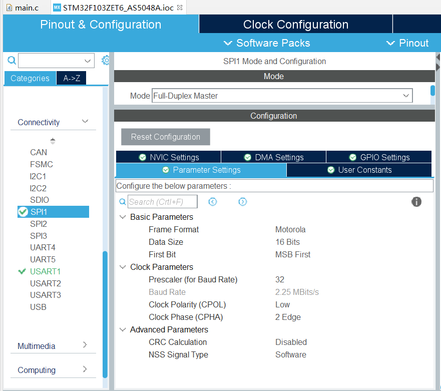
SPI1 is used as the communication interface of AS5048A for configuration:
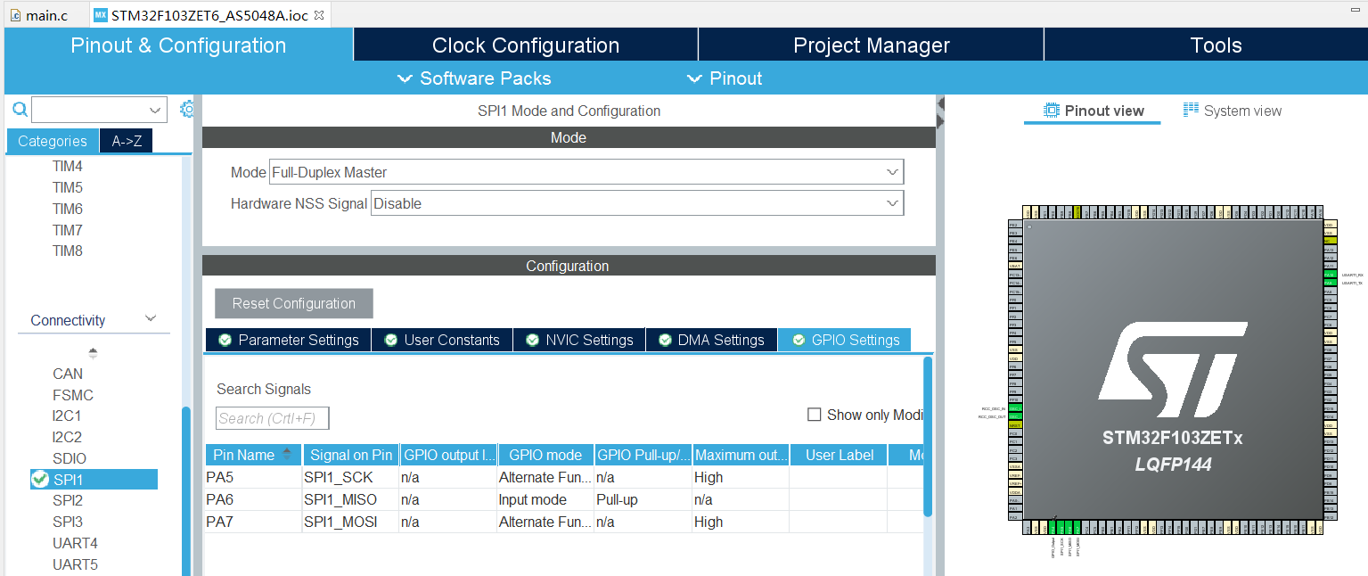
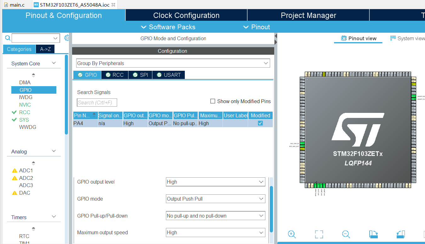
SPI chip selection signal is controlled by GPIO logic and needs to be configured separately:
Then realize the code, output the angle data through the serial port, the frame header is 0x55 0xaa, and then the angle data of 2 bytes and 16 bits. The 360 degree range corresponds to the output of 0 ~ (16384-1).
/* USER CODE BEGIN Header */
/**
******************************************************************************
* @file : main.c
* @brief : Main program body
******************************************************************************
* @attention
*
* <h2><center>© Copyright (c) 2020 STMicroelectronics.
* All rights reserved.</center></h2>
*
* This software component is licensed by ST under BSD 3-Clause license,
* the "License"; You may not use this file except in compliance with the
* License. You may obtain a copy of the License at:
* opensource.org/licenses/BSD-3-Clause
*
******************************************************************************
*/
//Written by Pegasus Yu
/* USER CODE END Header */
/* Includes ------------------------------------------------------------------*/
#include "main.h"
/* Private includes ----------------------------------------------------------*/
/* USER CODE BEGIN Includes */
/* USER CODE END Includes */
/* Private typedef -----------------------------------------------------------*/
/* USER CODE BEGIN PTD */
#define __AS5048A2_CS_ENABLE() HAL_GPIO_WritePin(GPIOA, GPIO_PIN_4, GPIO_PIN_RESET)
#define __AS5048A2_CS_DISABLE() HAL_GPIO_WritePin(GPIOA, GPIO_PIN_4, GPIO_PIN_SET)
#define __Read_NOP 0xc000
#define __Read_Clear_Error_Flag 0x4001
#define __Read_Angle 0xffff
/* USER CODE END PTD */
/* Private define ------------------------------------------------------------*/
/* USER CODE BEGIN PD */
/* USER CODE END PD */
/* Private macro -------------------------------------------------------------*/
/* USER CODE BEGIN PM */
/* USER CODE END PM */
/* Private variables ---------------------------------------------------------*/
SPI_HandleTypeDef hspi1;
UART_HandleTypeDef huart1;
/* USER CODE BEGIN PV */
/* USER CODE END PV */
/* Private function prototypes -----------------------------------------------*/
void SystemClock_Config(void);
static void MX_GPIO_Init(void);
static void MX_SPI1_Init(void);
static void MX_USART1_UART_Init(void);
/* USER CODE BEGIN PFP */
/* USER CODE END PFP */
/* Private user code ---------------------------------------------------------*/
/* USER CODE BEGIN 0 */
uint16_t SPI_TX_DATA[10]={0};
uint16_t SPI_RX_DATA[10]={0};
const uint8_t op_num = 4;
uint16_t origin_value = 0;
uint8_t i;
uint8_t TXD[4]={0};
uint16_t post_process_value=0;
/* USER CODE END 0 */
/**
* @brief The application entry point.
* @retval int
*/
int main(void)
{
/* USER CODE BEGIN 1 */
/* USER CODE END 1 */
/* MCU Configuration--------------------------------------------------------*/
/* Reset of all peripherals, Initializes the Flash interface and the Systick. */
HAL_Init();
/* USER CODE BEGIN Init */
/* USER CODE END Init */
/* Configure the system clock */
SystemClock_Config();
/* USER CODE BEGIN SysInit */
/* USER CODE END SysInit */
/* Initialize all configured peripherals */
MX_GPIO_Init();
MX_SPI1_Init();
MX_USART1_UART_Init();
/* USER CODE BEGIN 2 */
TXD[0]=0x55; TXD[1]=0xaa;//frame head
SPI_TX_DATA[0] = __Read_Clear_Error_Flag;
SPI_TX_DATA[1] = __Read_NOP;
SPI_TX_DATA[2] = __Read_Angle;
SPI_TX_DATA[3] = __Read_NOP;
for (i = 0; i<op_num; i++)
{
__AS5048A2_CS_ENABLE();
HAL_SPI_TransmitReceive (&hspi1, &SPI_TX_DATA[i], &SPI_RX_DATA[i], 1, 2710);
__AS5048A2_CS_DISABLE();
HAL_Delay(1);
}
origin_value = SPI_RX_DATA[3]&0x3fff;
/* USER CODE END 2 */
/* Infinite loop */
/* USER CODE BEGIN WHILE */
while (1)
{
/* USER CODE END WHILE */
/* USER CODE BEGIN 3 */
for (i = 0; i<op_num; i++)
{
__AS5048A2_CS_ENABLE();
HAL_SPI_TransmitReceive (&hspi1, &SPI_TX_DATA[i], &SPI_RX_DATA[i], 1, 2710);
__AS5048A2_CS_DISABLE();
HAL_Delay(1);
}
if ( (SPI_RX_DATA[3]&0x3fff)>=origin_value ) post_process_value= (SPI_RX_DATA[3]&0x3fff)-origin_value;
else post_process_value= 16384-origin_value+(SPI_RX_DATA[3]&0x3fff);
TXD[2] = (post_process_value&0xff00)>>8;
TXD[3]= post_process_value&0x00ff;
HAL_UART_Transmit(&huart1, TXD, 4, 0xffff);
HAL_Delay(1);
}
/* USER CODE END 3 */
}
/**
* @brief System Clock Configuration
* @retval None
*/
void SystemClock_Config(void)
{
RCC_OscInitTypeDef RCC_OscInitStruct = {0};
RCC_ClkInitTypeDef RCC_ClkInitStruct = {0};
/** Initializes the CPU, AHB and APB busses clocks
*/
RCC_OscInitStruct.OscillatorType = RCC_OSCILLATORTYPE_HSE;
RCC_OscInitStruct.HSEState = RCC_HSE_ON;
RCC_OscInitStruct.HSEPredivValue = RCC_HSE_PREDIV_DIV1;
RCC_OscInitStruct.HSIState = RCC_HSI_ON;
RCC_OscInitStruct.PLL.PLLState = RCC_PLL_ON;
RCC_OscInitStruct.PLL.PLLSource = RCC_PLLSOURCE_HSE;
RCC_OscInitStruct.PLL.PLLMUL = RCC_PLL_MUL9;
if (HAL_RCC_OscConfig(&RCC_OscInitStruct) != HAL_OK)
{
Error_Handler();
}
/** Initializes the CPU, AHB and APB busses clocks
*/
RCC_ClkInitStruct.ClockType = RCC_CLOCKTYPE_HCLK|RCC_CLOCKTYPE_SYSCLK
|RCC_CLOCKTYPE_PCLK1|RCC_CLOCKTYPE_PCLK2;
RCC_ClkInitStruct.SYSCLKSource = RCC_SYSCLKSOURCE_PLLCLK;
RCC_ClkInitStruct.AHBCLKDivider = RCC_SYSCLK_DIV1;
RCC_ClkInitStruct.APB1CLKDivider = RCC_HCLK_DIV2;
RCC_ClkInitStruct.APB2CLKDivider = RCC_HCLK_DIV1;
if (HAL_RCC_ClockConfig(&RCC_ClkInitStruct, FLASH_LATENCY_2) != HAL_OK)
{
Error_Handler();
}
}
/**
* @brief SPI1 Initialization Function
* @param None
* @retval None
*/
static void MX_SPI1_Init(void)
{
/* USER CODE BEGIN SPI1_Init 0 */
/* USER CODE END SPI1_Init 0 */
/* USER CODE BEGIN SPI1_Init 1 */
/* USER CODE END SPI1_Init 1 */
/* SPI1 parameter configuration*/
hspi1.Instance = SPI1;
hspi1.Init.Mode = SPI_MODE_MASTER;
hspi1.Init.Direction = SPI_DIRECTION_2LINES;
hspi1.Init.DataSize = SPI_DATASIZE_16BIT;
hspi1.Init.CLKPolarity = SPI_POLARITY_LOW;
hspi1.Init.CLKPhase = SPI_PHASE_2EDGE;
hspi1.Init.NSS = SPI_NSS_SOFT;
hspi1.Init.BaudRatePrescaler = SPI_BAUDRATEPRESCALER_32;
hspi1.Init.FirstBit = SPI_FIRSTBIT_MSB;
hspi1.Init.TIMode = SPI_TIMODE_DISABLE;
hspi1.Init.CRCCalculation = SPI_CRCCALCULATION_DISABLE;
hspi1.Init.CRCPolynomial = 10;
if (HAL_SPI_Init(&hspi1) != HAL_OK)
{
Error_Handler();
}
/* USER CODE BEGIN SPI1_Init 2 */
/* USER CODE END SPI1_Init 2 */
}
/**
* @brief USART1 Initialization Function
* @param None
* @retval None
*/
static void MX_USART1_UART_Init(void)
{
/* USER CODE BEGIN USART1_Init 0 */
/* USER CODE END USART1_Init 0 */
/* USER CODE BEGIN USART1_Init 1 */
/* USER CODE END USART1_Init 1 */
huart1.Instance = USART1;
huart1.Init.BaudRate = 115200;
huart1.Init.WordLength = UART_WORDLENGTH_8B;
huart1.Init.StopBits = UART_STOPBITS_1;
huart1.Init.Parity = UART_PARITY_NONE;
huart1.Init.Mode = UART_MODE_TX_RX;
huart1.Init.HwFlowCtl = UART_HWCONTROL_NONE;
huart1.Init.OverSampling = UART_OVERSAMPLING_16;
if (HAL_UART_Init(&huart1) != HAL_OK)
{
Error_Handler();
}
/* USER CODE BEGIN USART1_Init 2 */
/* USER CODE END USART1_Init 2 */
}
/**
* @brief GPIO Initialization Function
* @param None
* @retval None
*/
static void MX_GPIO_Init(void)
{
GPIO_InitTypeDef GPIO_InitStruct = {0};
/* GPIO Ports Clock Enable */
__HAL_RCC_GPIOA_CLK_ENABLE();
/*Configure GPIO pin Output Level */
HAL_GPIO_WritePin(GPIOA, GPIO_PIN_4, GPIO_PIN_SET);
/*Configure GPIO pin : PA4 */
GPIO_InitStruct.Pin = GPIO_PIN_4;
GPIO_InitStruct.Mode = GPIO_MODE_OUTPUT_PP;
GPIO_InitStruct.Pull = GPIO_NOPULL;
GPIO_InitStruct.Speed = GPIO_SPEED_FREQ_HIGH;
HAL_GPIO_Init(GPIOA, &GPIO_InitStruct);
}
/* USER CODE BEGIN 4 */
/* USER CODE END 4 */
/**
* @brief This function is executed in case of error occurrence.
* @retval None
*/
void Error_Handler(void)
{
/* USER CODE BEGIN Error_Handler_Debug */
/* User can add his own implementation to report the HAL error return state */
/* USER CODE END Error_Handler_Debug */
}
#ifdef USE_FULL_ASSERT
/**
* @brief Reports the name of the source file and the source line number
* where the assert_param error has occurred.
* @param file: pointer to the source file name
* @param line: assert_param error line source number
* @retval None
*/
void assert_failed(uint8_t *file, uint32_t line)
{
/* USER CODE BEGIN 6 */
/* User can add his own implementation to report the file name and line number,
tex: printf("Wrong parameters value: file %s on line %d\r\n", file, line) */
/* USER CODE END 6 */
}
#endif /* USE_FULL_ASSERT */
/************************ (C) COPYRIGHT STMicroelectronics *****END OF FILE****/
This routine continuously outputs the angle data read from AS5048A to USART1.
–End–