summary
There are two communication modes between CPU and peripherals: rotation training and interrupt; The so-called rotation training is to actively ask about a certain status to see if it is a certain value, and if so, take action; Once an interrupt occurs, it will actively notify the CPU; This chapter will study how to respond to key press events through rotation training.
Code overview
#include "stm32f10x_gpio.h"
#include "stm32f10x_rcc.h"
#include "../lib/STM32F10x_StdPeriph_Driver/inc/stm32f10x_exti.h"
#include "../lib/STM32F10x_StdPeriph_Driver/inc/misc.h"
#include "../lib/STM32F10x_StdPeriph_Driver/inc/stm32f10x_gpio.h"

void delay(unsigned int time)
{
    unsigned int i = 0;
    while (time--)
    {
        i = 1000000;
        while (i--)
            ;
    }
}

u8 key_read()
{
    u8 result = 0;
    result = GPIO_ReadInputDataBit(GPIOB, GPIO_Pin_12);

    return result;
}

void led_init()
{
    GPIO_InitTypeDef led;

    RCC_APB2PeriphClockCmd(RCC_APB2Periph_GPIOC, ENABLE);
    led.GPIO_Pin = GPIO_Pin_13;
    led.GPIO_Mode = GPIO_Mode_Out_PP;
    led.GPIO_Speed = GPIO_Speed_50MHz;
    GPIO_Init(GPIOC, &led);
    GPIO_WriteBit(GPIOC, GPIO_Pin_13, Bit_SET);
}

void key_init()
{
    GPIO_InitTypeDef key;

    RCC_APB2PeriphClockCmd(RCC_APB2Periph_GPIOB, ENABLE);
    key.GPIO_Pin = GPIO_Pin_12;
    key.GPIO_Mode = GPIO_Mode_IPD;
    // led.GPIO_Speed = GPIO_Speed_50MHz;
    GPIO_Init(GPIOB, &key);
    // GPIO_WriteBit(GPIOB, GPIO_Pin_12, Bit_RESET);
}

void led_opr(int opr){
    if(1 == opr){
        GPIO_WriteBit(GPIOC, GPIO_Pin_13, Bit_SET);
    }else{
        GPIO_WriteBit(GPIOC, GPIO_Pin_13, Bit_RESET);
    }
}

int main(void)
{
    led_init();
    key_init();
    key_nvid_init();
    while (1)
    {
        if (1 == key_read())
        {
            GPIO_WriteBit(GPIOC, GPIO_Pin_13, Bit_RESET);
        }
        else
        {
            GPIO_WriteBit(GPIOC, GPIO_Pin_13, Bit_SET);
        }
    }
    return 1;
}
Main function
Start with the main function to strip the cocoon and fix the implementation of the rotation training mode.
int main(void)
{
    led_init();
    key_init();
    while (1)
    {
                if (1 == key_read())
                {
                        GPIO_WriteBit(GPIOC, GPIO_Pin_13, Bit_RESET);
                }
                else
                {
                        GPIO_WriteBit(GPIOC, GPIO_Pin_13, Bit_SET);
                }
    }
    return 1;
}
LED initialization
void led_init()
{
    GPIO_InitTypeDef led;

    RCC_APB2PeriphClockCmd(RCC_APB2Periph_GPIOC, ENABLE);
    led.GPIO_Pin = GPIO_Pin_13;
    led.GPIO_Mode = GPIO_Mode_Out_PP;
    led.GPIO_Speed = GPIO_Speed_50MHz;
    GPIO_Init(GPIOC, &led);
    GPIO_WriteBit(GPIOC, GPIO_Pin_13, Bit_SET);
}
This is described in detail in "STM32 (4): Lighting LED based on component library". Turn left to see, enable the bus, do the initialization / configuration of PC13, and then the configuration takes effect. Finally, perform one-step operation and SET PC13 to SET, i.e. high level, so as to realize the effect of turning off the light. In this way, when you press the key, you can realize the lighting effect.
Keyboard operation initialization
void key_init()
{
    GPIO_InitTypeDef key;

    RCC_APB2PeriphClockCmd(RCC_APB2Periph_GPIOB, ENABLE);
    key.GPIO_Pin = GPIO_Pin_12;
    key.GPIO_Mode = GPIO_Mode_IPD;
    GPIO_Init(GPIOB, &key);
}
As you can see, keyboard initialization and LED initialization are very similar:
The first step is to define and initialize the GPIO configuration structure;
The second step is to configure GPIO;
The third step is to validate the GPIO configuration;
Pins used
A key of the keyboard is connected with the GPIOB12 pin, and the other end is connected with the 3v3 port; When the key is pressed, PB12 is connected to the 3.3v power supply, so PB12 becomes a high level (value is 1), and the light on and off can be determined according to whether the value of PB12 is high level or low level. 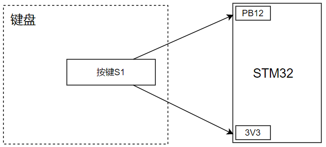
Pull up resistance vs. pull down resistance
The working mode of GPIO is IPD, i.e. Input Push Down, pull-down resistor. Why choose this working mode? First, the peripheral needs to transmit the level information to the GPIO pin, so the direction is Input. When the key is not pressed, it is floating. Therefore, it is necessary to pull down the floating level to low level through the pull-down resistance.
What is floating? Previously, we saw a pin, such as PC13 of LED, one end of which is either connected to power supply (VCC) or grounded; The grounding power supply is high level and the grounding is low level, which is clear. However, there is another case that there is neither grounding nor power supply. This is the case when the key is pressed. Under the condition, the power supplies of PB12 and 3V3 are connected, and PB12 is high level; However, when there is no down button, it is actually an unknown installation state, the level is between high and low levels, and the voltage value is unknown;
For the floating state, it is necessary to specify the level state, such as in the scene where the key is lit this time. Because the key is pressed, it is clear that it should be high level, so the state that is not pressed should be low level; Therefore, it is necessary to set the pull-down resistance in the working mode, so that the floating state will be treated as low level because there is a pull-down resistance circuit.
So what is A pull-down resistor? As shown in the figure below, if the GPIO port (the value range of x is A, B, C and other port groups, the number of port groups provided by STM32 of different levels is different, and the value range of y is 0 ~ 15, A total of 16 pins) should be high when the peripheral is connected, then the state should be low when floating / suspended (switch off). How can it be low when disconnected? It is to add A pull-down resistor on the GPIO. Because the switch is disconnected, it is equivalent to connecting an infinite resistor in series. It is lazy, or the former soft is afraid of hard circuit characteristics. The circuit goes through the pull-down resistor branch. Therefore, GPIOxy is in the low-power level filling position when the interface is floating; 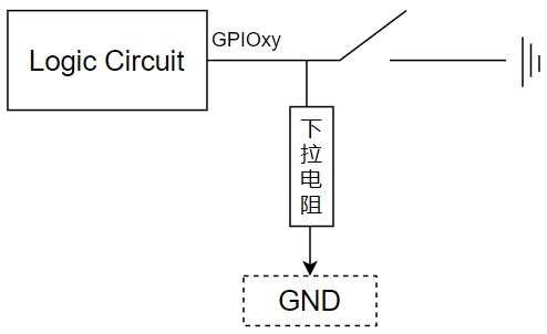
Similar to the pull-up resistor, the use scenario is just opposite to the pull-down resistor. It is suitable for the scenario where the other end of the switch is grounded and the floating state should be in the high-level state (the switch is turned on, because it is grounded, the Tieding port presents a low-level). As shown below, it is necessary to construct a pull-up resistor circuit according to the bullying characteristics of the circuit, The branch of the pull-up resistor is taken, so the switch is disconnected, and the specified interface presents a high level: 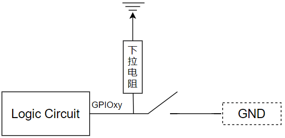 The following is a complete physical circuit diagram:
 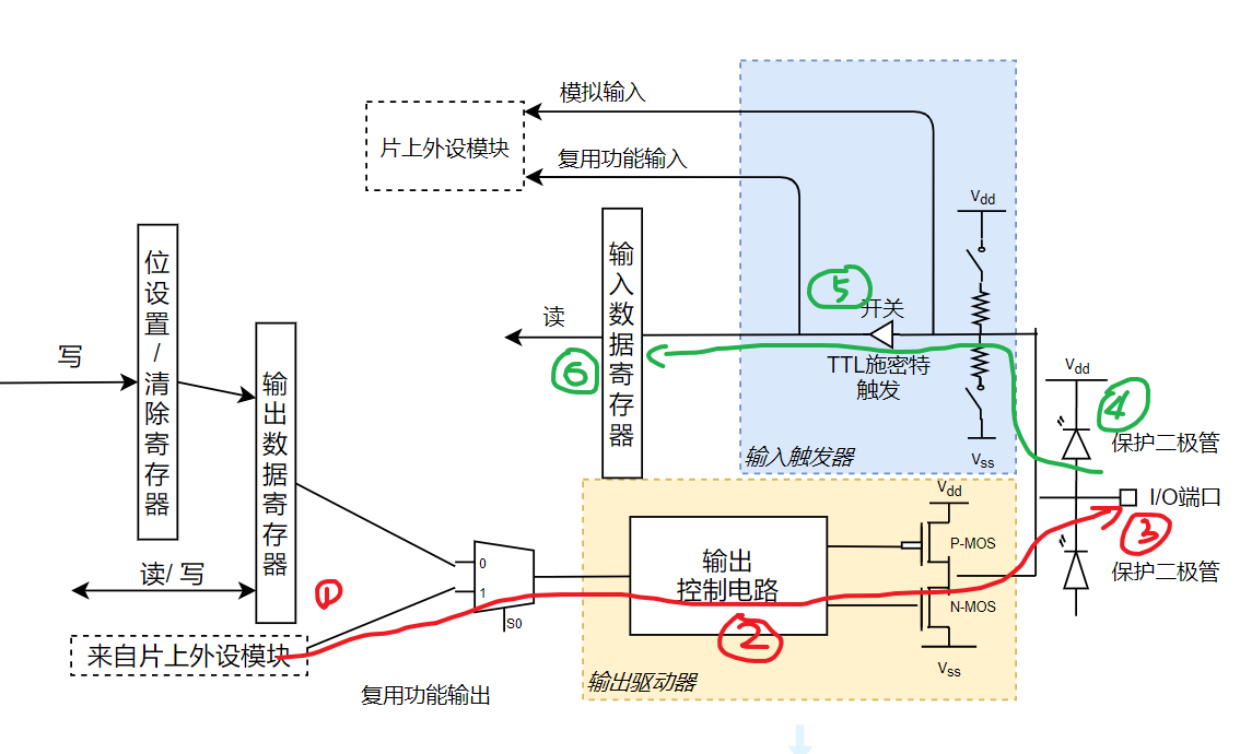 It can be seen that there will be a pull-up / pull-down resistance circuit inside the circuit to realize floating treatment;
GPIO speed
In the LED configuration, the working speed needs to be specified, but there is no working speed in the KEY configuration because of the specified GPIO_Speed is actually a sampling speed, that is, the state of the sampling GPIO pin. For example, if it is specified as 10MHz, that is, 10x100000 samples per second, it is used to obtain the semaphore. Therefore, according to Quist's theorem, the sampling frequency of GPIOSpeed should be at least 2 times of the signal frequency to accurately restore the original signal. Generally, it is 5 ~ 10 times in actual work;
Therefore, only the pin whose pin is the output mode needs to set the speed, because once a pin is configured as the output mode, it means that a signal is input to this pin and then output from this pin; Since there is a signal, if a pin wants to express the signal, it needs to be sampled, and the sampling speed needs to be specified;
For example, in the interpretation of the source code of lighting LED, the signal is the light on and off in the while cycle. The frequency of the signal is determined by the delay function in the while statement, and then write the signal to PC13:
int main(void)
{
        ... ...
        while (1)
        {
                GPIO_WriteBit(GPIOC, GPIO_Pin_13, Bit_SET);
                delay_2(1);
                GPIO_WriteBit(GPIOC, GPIO_Pin_13, Bit_RESET);
                delay_2(1);
        }
}
The CPU of the chip will collect based on the sampling frequency (GPIO_Speed), that is, the hardware level will sample; In fact, what really works is the sampling result, which directly determines the on and off of LED lights: 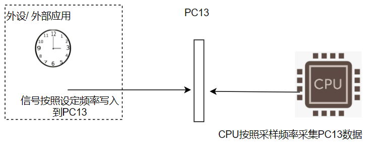
Input vs. output
Then, let's look back at the GPIO configuration of our keyboard. As the PB13 input pin, the data representing the pin is not actively written by the software. The input and output is from the perspective of the STM32 internal chip. The so-called input refers to that the peripheral writes data to the GPIO port, which needs to be obtained by the STM32 chip. For example, the buttons in this section are corresponding, That is, the peripheral (key) writes its own level state to PB12; Output, the signal generated by the internal circuit of STM32 is written to the GPIO port; For example, the high and low level control of PC13 in the LED lamp is directly controlled by the software level to the STM32 circuit, so if the software level directly configures the value of GPIO port (register), it is output; 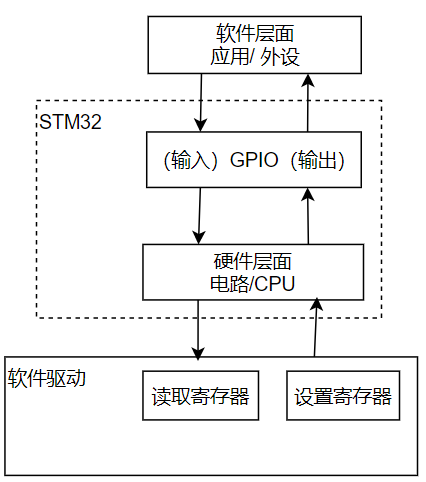
On and off of package lamp
void led_opr(int opr){ if(1 == opr){ GPIO_WriteBit(GPIOC, GPIO_Pin_13, Bit_SET); }else{ GPIO_WriteBit(GPIOC, GPIO_Pin_13, Bit_RESET); } }
This function determines whether to write high level or low level to PC13 according to the parameters; The writing method is described in "STM32 (4): Lighting LED based on component library". It is encapsulated as a function here to facilitate repeated calls; Bit_Set is to set the high level, Bit_Rest is low level. Remember the physical circuit diagram of LED?
If PC13 is set to 1, it is consistent with the voltage at VCC3V3 terminal and cannot form a voltage difference, so the LED lamp is off. Set PC13 to 0, and there is a voltage difference at both ends of LED2, so a current is generated (the current direction is VCC to PC13, the electronic direction is PC13 to VCC, high school physics knowledge).
GPIO_WriteBit is a library function (of STM32 firmware library), which is used to write high and low level values to GPIO pins.
Rotation mode communication
while (1)
{
        if (1 == key_read())
        {
                GPIO_WriteBit(GPIOC, GPIO_Pin_13, Bit_RESET);
        }
        else
        {
                GPIO_WriteBit(GPIOC, GPIO_Pin_13, Bit_SET);
        }
}
The following paragraph is to obtain the status of PB12 through rotation training (through the key_read function), and then set the status of PC13 according to the status of PB12; The so-called rotation training mode is to continuously obtain the state of the specified pin;
The rotation training is in sharp contrast to the interruption to be carried out later; Like some express delivery in Shanghai, you can only refresh your mobile phone again and again to see if it has been delivered and sent to pick it up. This is similar to "rotation communication"; After some conscience express delivery, you will be notified by SMS or phone. After receiving the notice, you can go downstairs to pick up the express. This is "interrupt communication";
Read pin status
Let's take a look at key_ Implementation of read():
u8 key_read()
{
        u8 result = 0;
        // delay(1);
        result = GPIO_ReadInputDataBit(GPIOB, GPIO_Pin_12);

        return result;
}
The library function GPIO (of STM32 firmware library) directly called here_ The readinputdatabit function realizes the reading of PB12. Here, if you are worried that frequent calls will affect the performance, you can use the key_ The while rotation training of the read or main main main function realizes the delay by calling the delay function; The disadvantage of rotation training is that it consumes CPU time and requires CPU to carry out rotation training continuously; Active notification of different interruptions requires active and continuous access; The advantage of interrupt will save CPU time, but not all events can adopt interrupt notification. There are only 256 preset interrupt types in STM32 (including 16 internal interrupts and 240 external interrupts).
summary
This chapter mainly introduces the realization of LED on-off control based on keys through rotation training; The main steps include LED initialization, key initialization and rotation training to read the pin status of PB12;
What you need to master is the principle and implementation of rotation training communication mechanism, as well as pin control related pull-up / pull-down resistance, GPIO speed and extended input / output concept,