1, Introduction
Universal synchronous asynchronous transceiver (USART) provides a flexible method for full duplex data exchange with external devices using the industry standard NRZ asynchronous serial data format. USART uses fractional baud rate generator to provide a wide range of baud rate options. It supports synchronous unidirectional communication and half duplex single line communication. It also supports Lin (local Internet), smart card protocol and IrDA (infrared data organization) SIR ENDEC specification, as well as modem (CTS/RTS) operation. It also allows multiprocessor communication. High speed data communication can be realized by using DMA mode with multi buffer configuration.
2, Hardware connection
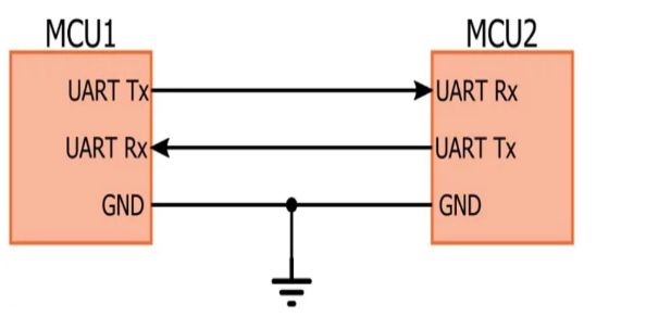
- Wiring mode between serial ports
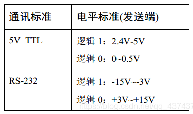
- Level standard of TTL and RS232
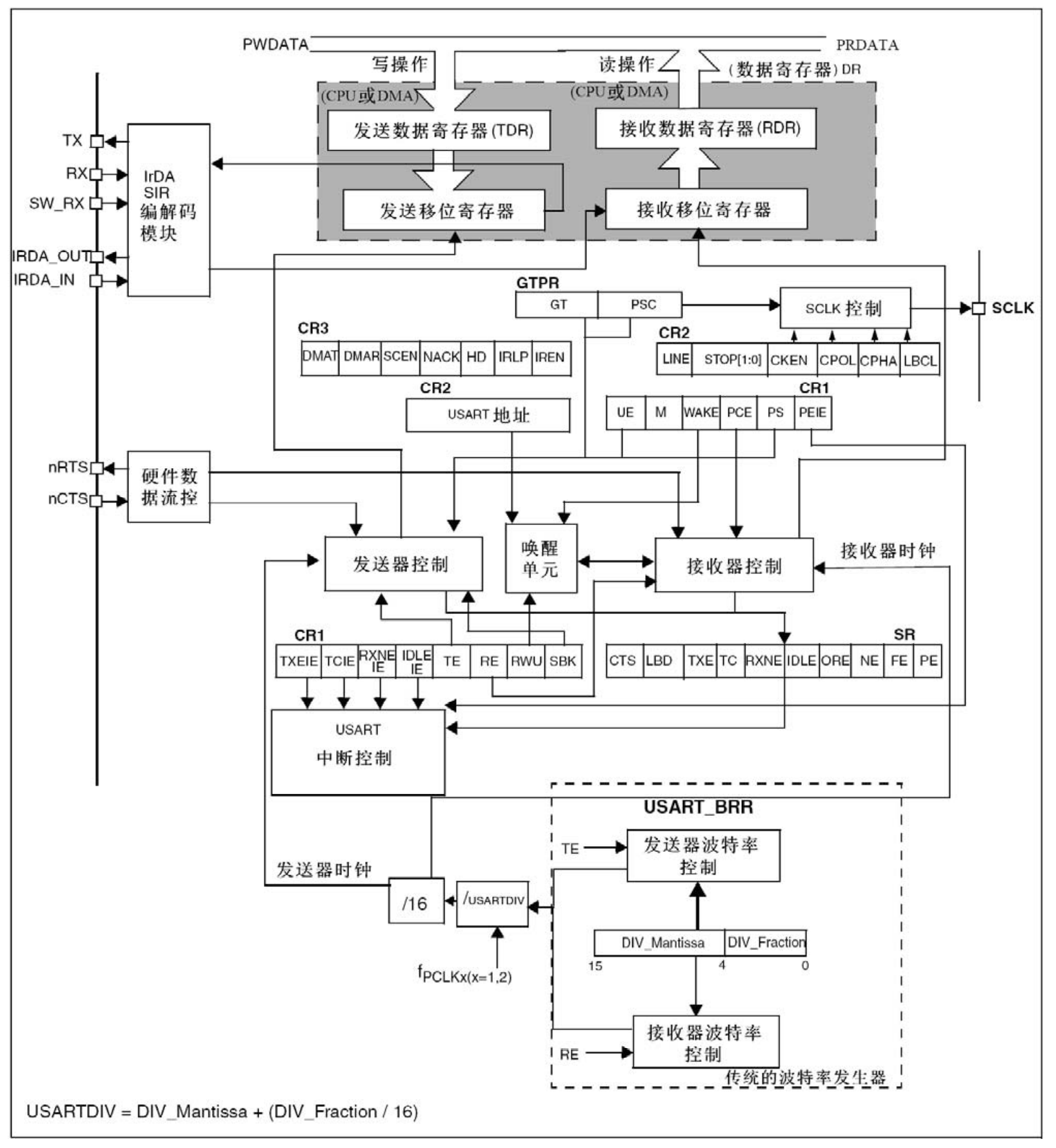
- STM32 USART block diagram
3, Communication protocol
-
data packet
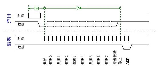
The data packet of serial communication is transmitted from the transmitting device to the RXD interface of the receiving device through its own TXD interface. The content of the data packet is specified in the protocol layer, including the start bit, main data (8 or 9 bits), check bit and stop bit. Both sides of communication must agree on the format of the data packet in order to send and receive data normally.
-
Baud rate
Since there is no clock signal in asynchronous communication, the receiver and the receiver should agree on the baud rate. The common baud rates are 4800, 9600, 115200, etc. -
Start and stop signals
The beginning and end of the data packet are start bit and stop bit respectively. The start signal of the data packet is represented by a data bit of logic 0, and the stop bit signal can be represented by data bits of 0.5, 1, 1.5 and 2 logic 1. Both parties shall agree. -
Valid data
Valid data specifies the length of subject data, generally 8 or 9 bits. -
data verification
After the valid data, there is an optional data check bit. Because the data communication is relatively vulnerable to external interference, resulting in the deviation of the transmitted data, the check bit can be added in the transmission process to solve this problem. The verification methods include odd, even, space, mark and noparity.
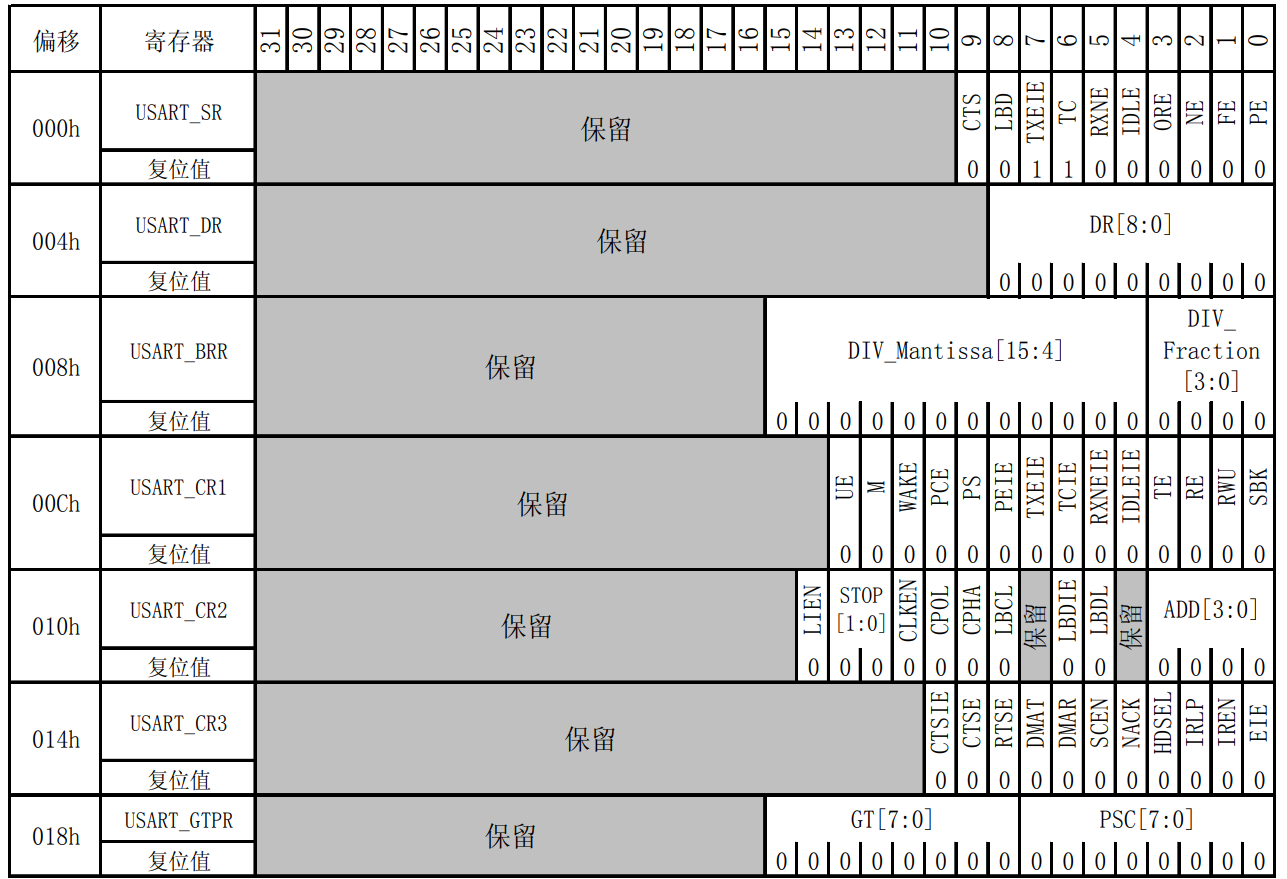
4. Register of STM32 USART
- STM32 USART's configured registers and the structural volume in the library function are encapsulated based on registers. If you haven't learned how to view registers, you can see my previous notes
| register | deviation | reset value | describe |
|---|---|---|---|
| USART_SR | 0x00 | 0x00C0 | Status register |
| USART_DR | 0x04 | uncertain | Data register |
| USART_BRR | 0x08 | 0x0000 | Baud ratio register |
| USART_CR1 | 0x0C | 0x0000 | Control register 1 |
| USART_CR2 | 0x10 | 0x0000 | Control register 2 |
| USART_CR3 | 0x14 | 0x0000 | Control register 3 |
| USART_GTPR | 0x18 | 0x0000 | Protection time and prescaler register |
- Address map of register
4, Code analysis
- Configure the structure of the serial port
typedef struct
{
    uint32_t USART_BaudRate;  // Baud rate setting
    uint16_t USART_WordLength;    //Data digit setting
    uint16_t USART_StopBits;    //stop bits setting
    uint16_t USART_Parity;    //Parity check or not
    uint16_t USART_Mode;    //Both receive and transmit are enabled
    uint16_t USART_HardwareFlowControl;      //Hardware flow control mode setting
} USART_InitTypeDef;
- Interrupt configuration structure
typedef struct
{
    uint8_t NVIC_IRQChannel;    // Configure USART as interrupt source
    uint8_t NVIC_IRQChannelPreemptionPriority;    // Preemption priority
    uint8_t NVIC_IRQChannelSubPriority;    // Sub priority
    FunctionalState NVIC_IRQChannelCmd;    // Enable interrupt
} NVIC_InitTypeDef;
- Configure IO pin of USART
Tx is configured as multiplexed push-pull output and Rx is configured as floating input
    /* USART1 Use IO port configuration */
    GPIO_InitStructure.GPIO_Pin = GPIO_Pin_9;
    GPIO_InitStructure.GPIO_Mode = GPIO_Mode_AF_PP; //Multiplexed push-pull output
    GPIO_InitStructure.GPIO_Speed = GPIO_Speed_50MHz;
    GPIO_Init(GPIOA, &GPIO_InitStructure);

    GPIO_InitStructure.GPIO_Pin = GPIO_Pin_10;
    GPIO_InitStructure.GPIO_Mode = GPIO_Mode_IN_FLOATING;	//Floating input
    GPIO_Init(GPIOA, &GPIO_InitStructure);   //Initialize GPIOA
- Configure the working mode configuration of USART
    /* USART1 Working mode configuration */
    USART_InitStructure.USART_BaudRate = 115200;	//Baud rate setting: 115200
    USART_InitStructure.USART_WordLength = USART_WordLength_8b;	//Data digit setting: 8 digits
    USART_InitStructure.USART_StopBits = USART_StopBits_1; 	//Stop bit setting: 1 bit
    USART_InitStructure.USART_Parity = USART_Parity_No ;  //Parity check or not: None
    USART_InitStructure.USART_HardwareFlowControl = USART_HardwareFlowControl_None;	//Hardware flow control mode setting: not enabled
    USART_InitStructure.USART_Mode = USART_Mode_Rx | USART_Mode_Tx;//Both receive and transmit are enabled
- Configure Rx read to interrupt read mode
void NVIC_Configuration(void)
{
    NVIC_InitTypeDef NVIC_InitStructure;

    NVIC_PriorityGroupConfig(NVIC_PriorityGroup_2);		// Set NVIC interrupt packet 2: 2-bit preemption priority and 2-bit response priority

    NVIC_InitStructure.NVIC_IRQChannel = USART1_IRQn;		// Configure USART as interrupt source
    NVIC_InitStructure.NVIC_IRQChannelPreemptionPriority = 3;		// Preemption priority
    NVIC_InitStructure.NVIC_IRQChannelSubPriority = 3;		// Sub priority
    NVIC_InitStructure.NVIC_IRQChannelCmd = ENABLE;		// Enable interrupt
    NVIC_Init(&NVIC_InitStructure);		// Initialize and configure NVIC
}
- Interrupt function usage
When the serial port receives data, this interrupt function will be called. After calling this function, the received information will be sent and obtained through the serial port. The interrupt function name here has been defined in the startup file. It is recommended not to change it.
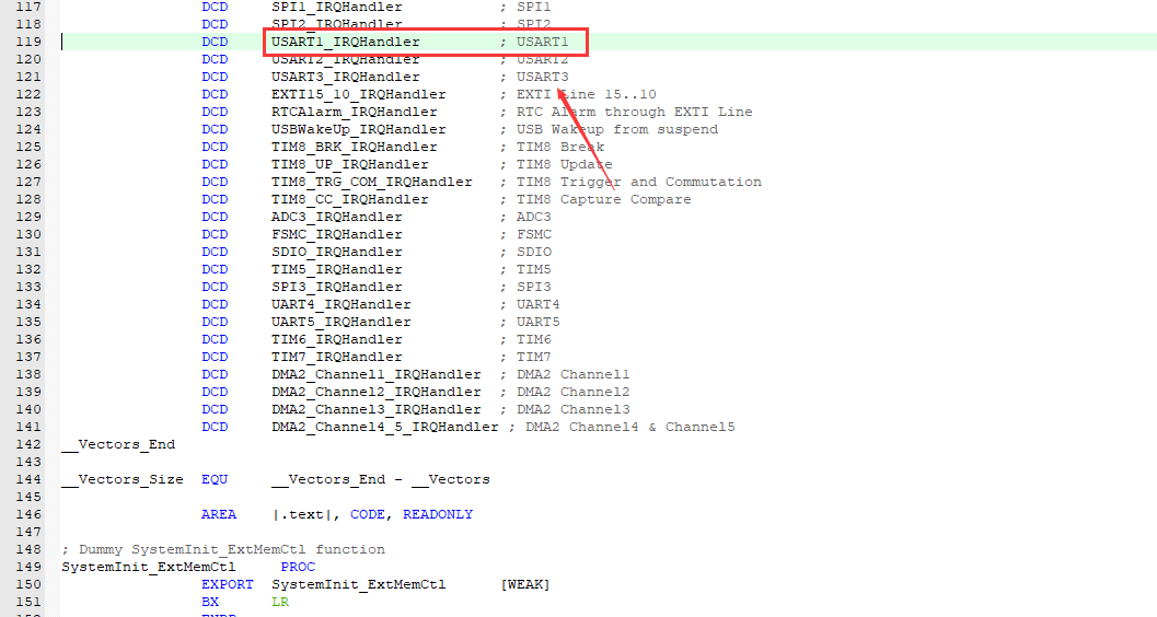
Note: after writing the program, some partners find that the serial port cannot receive the sent information. It may be that the interrupt function name here is written incorrectly.
void USART1_IRQHandler(void)
{
	uint16_t  res;
	/* Judge whether the interrupt signal is received */
	if(USART_GetITStatus(USART1, USART_IT_RXNE) == SET)
	{
		res = USART_ReceiveData(USART1);
		USART_SendData(USART1, res);
	}
	//USART_SendData(USART1,(uint16_t)0xAC);

}
5, Program source code
- usart1.c Documents
/***************************************
 * File name: usart1 c
 * Description: configure USART1
 * Experimental platform: MINI STM32 development board based on STM32F103C8T6
 * Hardware connection:------------------------
 *          | PA9  - USART1(Tx)      |
 *          | PA10 - USART1(Rx)      |
 *           ------------------------


**********************************************************************************/

#include "usart1.h"
#include <stdarg.h>
#include "misc.h"


void NVIC_Configuration(void)
{
	NVIC_InitTypeDef NVIC_InitStructure;

	NVIC_PriorityGroupConfig(NVIC_PriorityGroup_2);		// Set NVIC interrupt packet 2: 2-bit preemption priority and 2-bit response priority

	NVIC_InitStructure.NVIC_IRQChannel = USART1_IRQn;		// Configure USART as interrupt source
	NVIC_InitStructure.NVIC_IRQChannelPreemptionPriority = 3;		// Preemption priority
	NVIC_InitStructure.NVIC_IRQChannelSubPriority = 3;		// Sub priority
	NVIC_InitStructure.NVIC_IRQChannelCmd = ENABLE;		// Enable interrupt
	NVIC_Init(&NVIC_InitStructure);		// Initialize and configure NVIC
}


void USART1_Config(void)
{
	GPIO_InitTypeDef GPIO_InitStructure;
	USART_InitTypeDef USART_InitStructure;

	/* Enable USART1 clock*/
	RCC_APB2PeriphClockCmd(RCC_APB2Periph_USART1 | RCC_APB2Periph_GPIOA, ENABLE);

	/* USART1 Use IO port configuration */
	GPIO_InitStructure.GPIO_Pin = GPIO_Pin_9;
	GPIO_InitStructure.GPIO_Mode = GPIO_Mode_AF_PP; //Multiplexed push-pull output
	GPIO_InitStructure.GPIO_Speed = GPIO_Speed_50MHz;
	GPIO_Init(GPIOA, &GPIO_InitStructure);

	GPIO_InitStructure.GPIO_Pin = GPIO_Pin_10;
	GPIO_InitStructure.GPIO_Mode = GPIO_Mode_IN_FLOATING;	//Floating input
	GPIO_Init(GPIOA, &GPIO_InitStructure);   //Initialize GPIOA

	/* USART1 Working mode configuration */
	USART_InitStructure.USART_BaudRate = 115200;	//Baud rate setting: 115200
	USART_InitStructure.USART_WordLength = USART_WordLength_8b;	//Data digit setting: 8 digits
	USART_InitStructure.USART_StopBits = USART_StopBits_1; 	//Stop bit setting: 1 bit
	USART_InitStructure.USART_Parity = USART_Parity_No ;  //Parity check or not: None
	USART_InitStructure.USART_HardwareFlowControl = USART_HardwareFlowControl_None;	//Hardware flow control mode setting: not enabled
	USART_InitStructure.USART_Mode = USART_Mode_Rx | USART_Mode_Tx;//Both receive and transmit are enabled

	USART_Init(USART1, &USART_InitStructure);  //Initialize USART1
	USART_Cmd(USART1, ENABLE);// USART1 enable


	USART_ITConfig(USART1, USART_IT_RXNE, ENABLE);	// Open serial port to accept interrupt
	NVIC_Configuration();// Serial port interrupt priority configuration


}

void USART1_IRQHandler(void)
{
	uint16_t  res;
	/* Judge whether the interrupt signal is received */
	if(USART_GetITStatus(USART1, USART_IT_RXNE) == SET)
	{
		res = USART_ReceiveData(USART1);
		USART_SendData(USART1, res);
	}
	//USART_SendData(USART1,(uint16_t)0xAC);

}
- main.c Documents
#include "stm32f10x.h"
#include "usart1.h"


int main(void)
{

    SystemInit();	//Configure the system clock to 72M

	USART1_Config(); //USART1 configuration

	while (1)
	{

	}
}
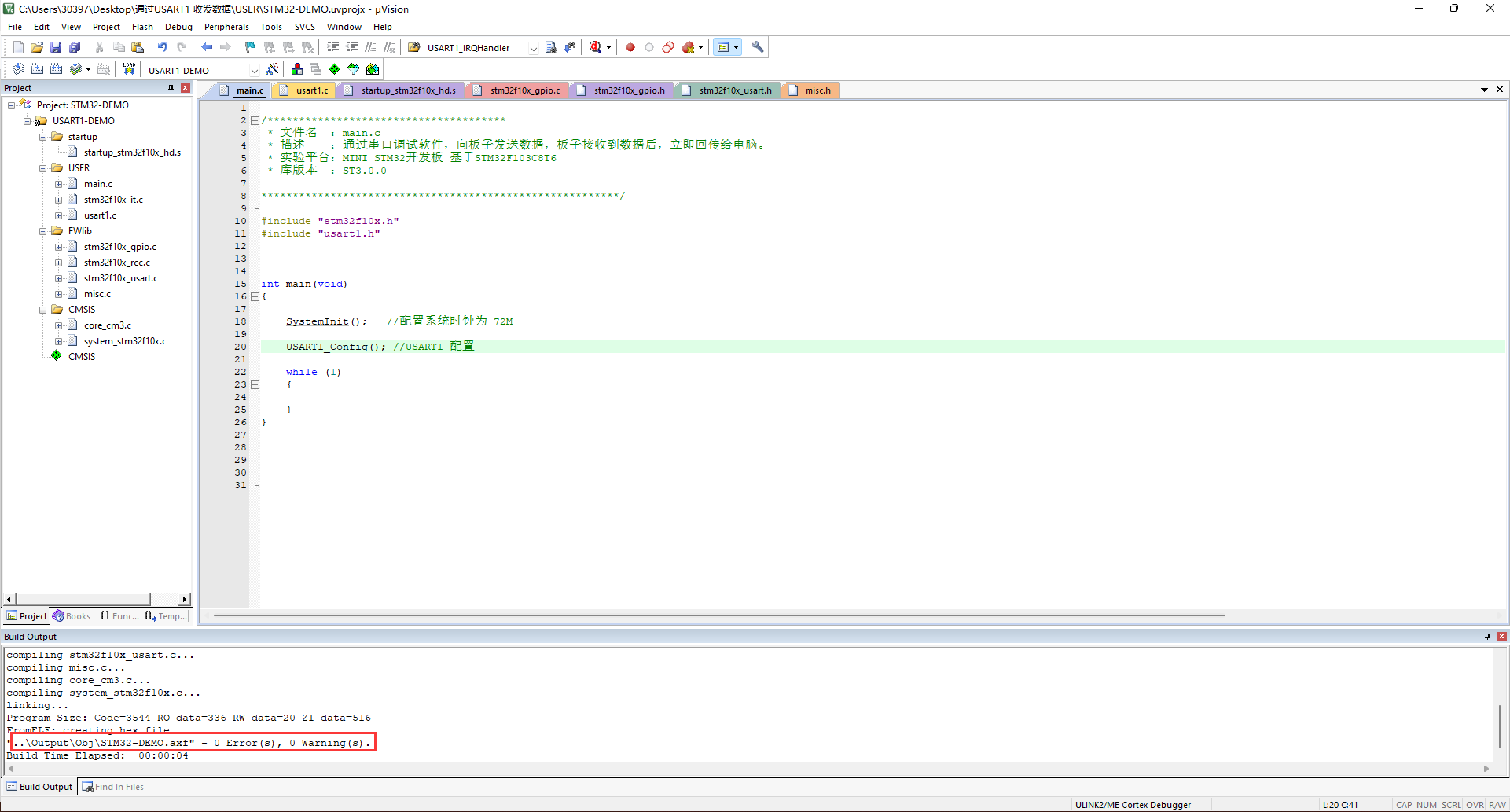
5, Compile run
-
compile
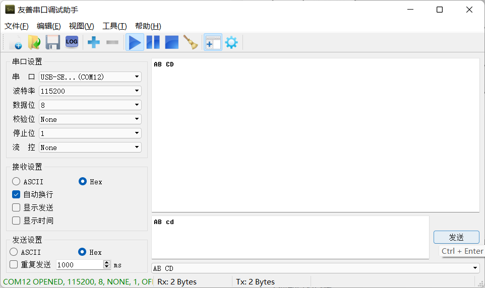
-
function
6, Frequently asked questions
After downloading and running, the program sends data without feedback.
terms of settlement:
- Check whether the interrupt function name is correct.
- Set the STM32 pin to the operation mode. If you don't know how to set it to the operation mode, you can refer to it STM32 zero foundation tutorial.