Continue to pay attention to Ajie's online update of nanny notes ~ ~ adhere to the daily shift
Reference: STM32 Chinese reference manual V10 - Chapter 9 interrupts and events
catalogue
1, NVIC interrupt priority grouping
Interrupt priority packet register
Describe the difference between preemption priority and response priority:
Interrupt priority grouping library function
2, NVIC interrupt priority setting
Interrupt priority setting register
Interrupt priority setting library function
1, NVIC interrupt priority grouping
In fact, kernel interrupt is also called kernel exception.
- Interruption means that the system stops the currently running program and turns to other services. It may be that the program receives a request higher than its own height, or it is artificially set. Interruption is a normal phenomenon.
- Exceptions refer to errors caused by cpu failure, program failure or service request. Exceptions are abnormal phenomena.
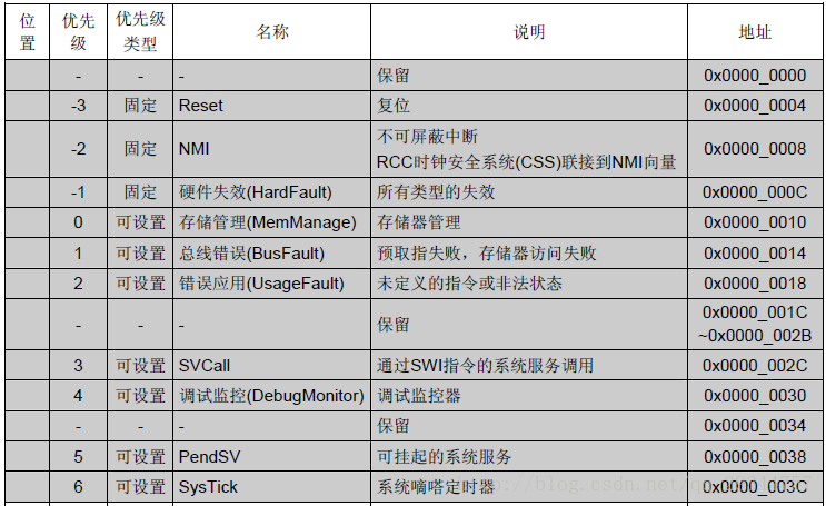
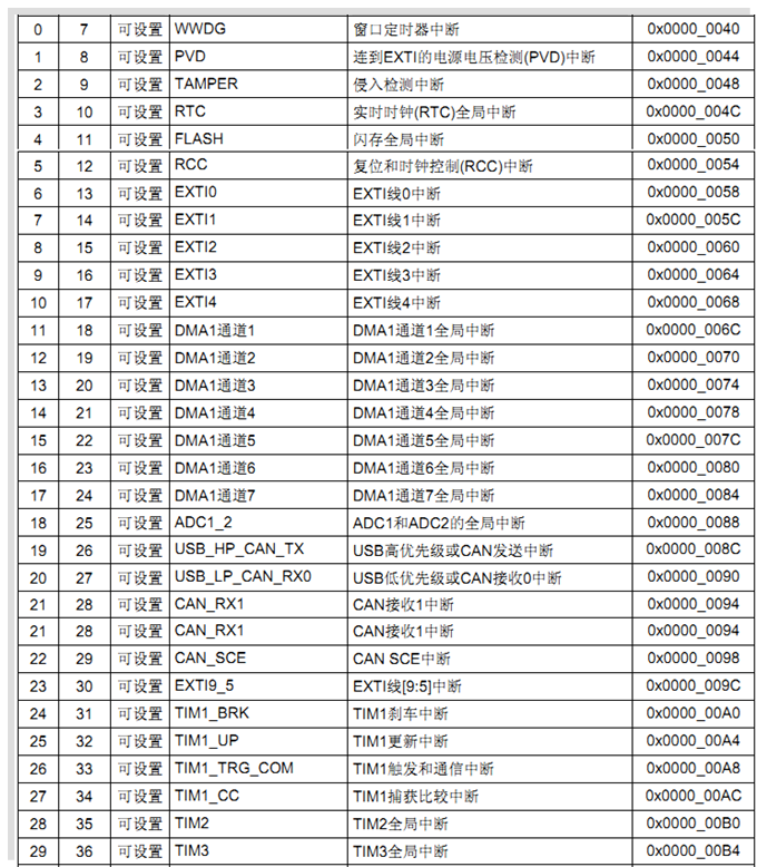
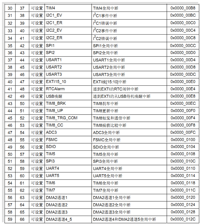
In the interrupt vector table, priority 7-66 (interrupt number from 0-59) represents 60 interrupts of STM32F103. The smaller the priority number, the higher the priority. When an exception or interrupt in the table is triggered, the program counter pointer (PC) will jump to the address of the exception or interrupt for execution, where this jump instruction is stored, and jump to the service function of the exception or interrupt to execute the corresponding function. Therefore, exception and interrupt vector tables can only be written in assembly language.
In MDK, there are standard exception and interrupt vector table files that can be used (startup_stm32f10x_hd.s), in which the name of the interrupt handling function is indicated, which cannot be defined arbitrarily. Interrupt channel NVIC_IRQChannel (i.e. IRQn_Type) is in stm32f10x H file.
What is NVIC? Nested vector interrupt controller. There is a powerful and convenient NVIC in CM3, which belongs to the cortex core. It handles 60 interrupts in the interrupt vector table. NVIC is a part of the core of Cortex-M3. The information about it is not in the technical reference manual of STM32. Please refer to the Cortex-M3 technical reference manual of ARM company. Vector interrupts of Cortex-M3 are uniformly managed by NVIC.
The core functions of NVIC are interrupt priority grouping, interrupt priority configuration, read interrupt request flag, clear interrupt request flag, enable interrupt, clear interrupt, etc. it controls 60 interrupts with interrupt number 0-59 in STM32 interrupt vector table!! The external interrupt signal is sent from outside the core, and the signal is finally transmitted to NVIC (nested vector interrupt controller). NVIC is closely coupled with the kernel, which controls the related functions of the interrupt of the whole chip.
Interrupt priority packet register
How to manage dozens of interruptions?
Firstly, STM32 interrupts are grouped. STM32 can divide interrupts into five groups, namely groups 0-4; At the same time, set a preemption priority and response priority for each interrupt. The packet configuration is defined by bit10-8 of SCB - > aircr register. Where is SCB - > aircr? Since this is defined by the CM3 kernel, it can be found in the document Cortex-M3 authoritative guide (Chinese).
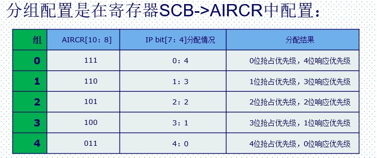
The AIRCR register determines which packet is used, and the IP register is the allocation proportion corresponding to the preemption priority and response priority of that packet. For example, if the group is set to 3, the highest 3 bits of the upper 4 bits of all 60 interrupt priority registers are preemptive priority, and the lower 1 Bit is response priority. Eight bits are defined in CM3 to set the priority of interrupt source, while STM32 selects only four of them.
Describe the difference between preemption priority and response priority:
(the level of preemption priority is higher than the response priority, and the smaller the value, the higher the priority. )
- The preemption priority of high priority can interrupt the ongoing interruption of low preemption priority;
- For interrupts with the same preemptive priority, high response priority cannot interrupt interrupts with low response priority;
- For interrupts with the same preemptive priority, when two interrupts occur at the same time, which response priority is higher and which is executed first;
- If the preemption priority and response priority of two interrupts are the same, it depends on which interrupt occurs first;
In addition, there are two points to note:
- Interruptions are only related to preemption priority, not response priority!
- In general, during the execution of system code, only one interrupt priority group is set, such as group 2. Generally, the group will not be changed after setting the group. Arbitrarily changing the grouping will lead to confusion of interrupt management and unexpected execution results of the program.
Interrupt priority grouping library function
The priority grouping mode of CM3 core uses the setting function NVIC_SetPriorityGrouping().
Next, the interrupt priority grouping function NVIC of STM32 is introduced_ Prioritygroupconfig() is used to set interrupt grouping. This function is misc. In the firmware library C in the document
void NVIC_PriorityGroupConfig(uint32_t NVIC_PriorityGroup)
{
  /* Check the parameters */
  assert_param(IS_NVIC_PRIORITY_GROUP(NVIC_PriorityGroup));

  /* Set the PRIGROUP[10:8] bits according to NVIC_PriorityGroup value */
  SCB->AIRCR = AIRCR_VECTKEY_MASK | NVIC_PriorityGroup;
}
The values of the parameters of the function are defined in the same file:
#define NVIC_PriorityGroup_0         ((uint32_t)0x700) /*!< 0 bits for pre-emption priority
                                                            4 bits for subpriority */
#define NVIC_PriorityGroup_1         ((uint32_t)0x600) /*!< 1 bits for pre-emption priority
                                                            3 bits for subpriority */
#define NVIC_PriorityGroup_2         ((uint32_t)0x500) /*!< 2 bits for pre-emption priority
                                                            2 bits for subpriority */
#define NVIC_PriorityGroup_3         ((uint32_t)0x400) /*!< 3 bits for pre-emption priority
                                                            1 bits for subpriority */
#define NVIC_PriorityGroup_4         ((uint32_t)0x300) /*!< 4 bits for pre-emption priority
                                                            0 bits for subpriority */
2, NVIC interrupt priority setting
Interrupt priority setting register
After the grouping is set, how to set the preemption priority and response priority of a single interrupt?
MDK defines the following structure for registers related to NVIC and controls 60 interrupts in the interrupt vector table (defined in the core_cm3.h file because it is related to the interrupt kernel):
typedef struct
{
  __IO uint32_t ISER[8];                      /*!< Offset: 0x000  Interrupt Set Enable Register           */
       uint32_t RESERVED0[24];
  __IO uint32_t ICER[8];                      /*!< Offset: 0x080  Interrupt Clear Enable Register         */
       uint32_t RSERVED1[24];
  __IO uint32_t ISPR[8];                      /*!< Offset: 0x100  Interrupt Set Pending Register          */
       uint32_t RESERVED2[24];
  __IO uint32_t ICPR[8];                      /*!< Offset: 0x180  Interrupt Clear Pending Register        */
       uint32_t RESERVED3[24];
  __IO uint32_t IABR[8];                      /*!< Offset: 0x200  Interrupt Active bit Register           */
       uint32_t RESERVED4[56];
  __IO uint8_t  IP[240];                      /*!< Offset: 0x300  Interrupt Priority Register (8Bit wide) */
       uint32_t RESERVED5[644];
  __O  uint32_t STIR;                         /*!< Offset: 0xE00  Software Trigger Interrupt Register     */
}  NVIC_Type;
Let's introduce these registers in turn:
First introduce several registers with a length of 8. These registers are 32-bit registers. Since STM32 has only 60 maskable interrupts, only two of the eight 32-bit registers need 64 bits, and each bit controls an interrupt.
- ISER[8] (interrupt set enable registers): interrupt enable registers. Only ISER[0] and ISER[1] are used, and bit0~bit31 of ISER[0] correspond to interrupt 0 ~ 31 respectively. bit0~27 of ISER[1] corresponds to interrupt 32 ~ 59. To enable an interrupt, you must set the corresponding ISER bit to 1 to enable the interrupt (this is only enabled, and it is complete only with the settings of interrupt grouping, shielding, I/O port mapping, etc.). Refer to stm32f103x for the interrupt corresponding to each bit Line 140 in H.
- ICER[8] (interrupt clear enable registers): interrupt remove registers. The function of this register is opposite to that of ISER. Here, an ICER is specially set to clear the middle break bit instead of writing 0 to the ISER bit, because writing 1 to the register of NVIC is valid and writing 0 is invalid.
- ISPR[8] (interrupt set pending registers): interrupt pending control register. By setting 1, you can suspend the ongoing interrupt and execute the interrupt of the same level or higher. Invalid write 0.
- ICPR[8] (interrupt clear pending registers): interrupt uncoupling control register. By setting 1, you can unhook the pending interrupt. Invalid write 0.
- IABR[8] (interrupt active bit registers): interrupt active flag bit register. This is a read-only register. You can know which interrupt is currently executing (1). After the interrupt is executed, the hardware will automatically reset.
- Finally, a register group with a length of 240 is introduced, which is an 8-bit register. 240 8-bit registers, one for each interrupt to determine priority. Since CM3 consists of 240 external interrupts, the number of this register group is 240 (note the difference from the above registers: one register controls one, and one bit controls one).
- IP[240] (Interrupt Priority Registers): registers for interrupt priority control. This is used to control the priority of each interrupt. Since there are 60 maskable interrupts in STM32F10x series, IP[59]~IP[0] is used. The upper 4 bits [7:4] of each IP register are used to set the preemption and response priority (according to the packet), and the lower 4 bits are not used. The number of bits occupied by the two priorities is determined by the interrupt priority grouping mentioned above.
Interrupt priority setting library function
Next, we will introduce how to use the library function to realize interrupt priority management. Here, NVIC is used_ Init() function to set the priority of each interrupt (in misc.c file):
void NVIC_Init(NVIC_InitTypeDef* NVIC_InitStruct)
{
  uint32_t tmppriority = 0x00, tmppre = 0x00, tmpsub = 0x0F;

  /* Check the parameters */
  assert_param(IS_FUNCTIONAL_STATE(NVIC_InitStruct->NVIC_IRQChannelCmd));
  assert_param(IS_NVIC_PREEMPTION_PRIORITY(NVIC_InitStruct->NVIC_IRQChannelPreemptionPriority));
  assert_param(IS_NVIC_SUB_PRIORITY(NVIC_InitStruct->NVIC_IRQChannelSubPriority));

  if (NVIC_InitStruct->NVIC_IRQChannelCmd != DISABLE)
  {
    /* Compute the Corresponding IRQ Priority --------------------------------*/
    tmppriority = (0x700 - ((SCB->AIRCR) & (uint32_t)0x700))>> 0x08;
    tmppre = (0x4 - tmppriority);
    tmpsub = tmpsub >> tmppriority;

    tmppriority = (uint32_t)NVIC_InitStruct->NVIC_IRQChannelPreemptionPriority << tmppre;
    tmppriority |=  NVIC_InitStruct->NVIC_IRQChannelSubPriority & tmpsub;
    tmppriority = tmppriority << 0x04;

    NVIC->IP[NVIC_InitStruct->NVIC_IRQChannel] = tmppriority;

    /* Enable the Selected IRQ Channels --------------------------------------*/
    NVIC->ISER[NVIC_InitStruct->NVIC_IRQChannel >> 0x05] =
      (uint32_t)0x01 << (NVIC_InitStruct->NVIC_IRQChannel & (uint8_t)0x1F);
  }
  else
  {
    /* Disable the Selected IRQ Channels -------------------------------------*/
    NVIC->ICER[NVIC_InitStruct->NVIC_IRQChannel >> 0x05] =
      (uint32_t)0x01 << (NVIC_InitStruct->NVIC_IRQChannel & (uint8_t)0x1F);
  }
}
Among them, NVIC_InitTypeDef is a structure whose member variables are:
typedef struct
{
  uint8_t NVIC_IRQChannel;                    /*!< Specifies the IRQ channel to be enabled or disabled.
                                                   This parameter can be a value of @ref IRQn_Type
                                                   (For the complete STM32 Devices IRQ Channels list, please
                                                    refer to stm32f10x.h file) */

  uint8_t NVIC_IRQChannelPreemptionPriority;  /*!< Specifies the pre-emption priority for the IRQ channel
                                                   specified in NVIC_IRQChannel. This parameter can be a value
                                                   between 0 and 15 as described in the table @ref NVIC_Priority_Table */

  uint8_t NVIC_IRQChannelSubPriority;         /*!< Specifies the subpriority level for the IRQ channel specified
                                                   in NVIC_IRQChannel. This parameter can be a value
                                                   between 0 and 15 as described in the table @ref NVIC_Priority_Table */

  FunctionalState NVIC_IRQChannelCmd;         /*!< Specifies whether the IRQ channel defined in NVIC_IRQChannel
                                                   will be enabled or disabled.
                                                   This parameter can be set either to ENABLE or DISABLE */
} NVIC_InitTypeDef;
NVIC_ The inittypedef structure has four member variables:
- NVIC_IRQChannel: defines which interrupt is initialized. This can be found in stm32f10x Check the name of each interrupt file, such as the name of ART1_ IRQn;
- NVIC_IRQChannelPreemptionPriority: defines the preemption priority of this interrupt;
- NVIC_IRQChannelSubPriority: defines the response priority of this interrupt;
- NVIC_IRQChannelCmd: whether the interrupt is enabled.
Actually, let's look at NVIC_ The internal enable interrupt of init() function is also configured through ISER register. This is not inconsistent with our previous content. The function uses NVIC - > ISER internally, and NVIC is a macro definition,
#define NVIC ((NVIC_Type *) NVIC_BASE) /*!< NVIC configuration struct */
That is, directly operate the structure to operate the ISER register.
For example, if serial port 1 interrupt is enabled, the preemption priority is 1 and the response priority is 2. The initialization method is as follows:
NVIC_InitTypeDef   NVIC_InitStructure;
NVIC_InitStructure.NVIC_IRQChannel = USART1_IRQn;//Serial port 1 interrupt
NVIC_InitStructure.NVIC_IRQChannelPreemptionPriority=1 ;// Preemption priority is 1
NVIC_InitStructure.NVIC_IRQChannelSubPriority = 2;// Sub priority bit 2
NVIC_InitStructure.NVIC_IRQChannelCmd = ENABLE;//IRQ channel enable
NVIC_Init(&NVIC_InitStructure);	//Initialize the NVIC register according to the parameters specified above
3, NVIC summary
Finally, summarize the steps of interrupt priority setting:
1. Set interrupt priority group after system operation. Call function:
void NVIC_PriorityGroupConfig(uint32_t NVIC_PriorityGroup);
During the execution of the whole system, only one interrupt packet is set;
2. Set the corresponding preemption priority and response priority for each interrupt:
void NVIC_Init(NVIC_InitTypeDef* NVIC_InitStruct);
3. If you need to suspend / unhook, check the current activation status of the interrupt and call the relevant functions respectively.