preface
I, Xiaobai, recently read some information about CAN protocol and bxCAN peripherals of STM32, and simply do a CAN loop test exercise. This is just a simple practice record for beginners. If you study, you still need to see the corresponding tutorial.
Tools and versions used:
STM32CubeMX version: 6.3 0
HAL Library: stm32cubef4 firmware package v1 twenty-six point one
MDK-ARM: V5.32.0.0
Development board: Wildfire Decepticon development board V2 (the main control chip is STM32F407ZGT6)
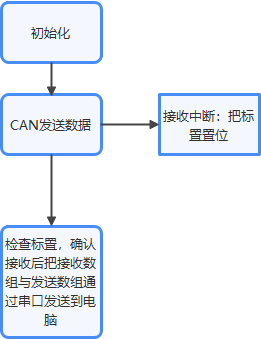
The approximate block diagram is as follows:
STM32CubeMX generates initialization code
Clock and serial port configuration are omitted.
About CAN configuration:
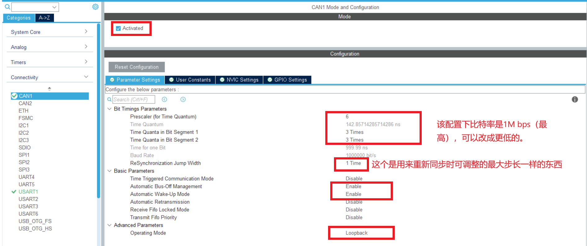
Open CAN1 RX0 interrupt permission in NVIC and set the priority.
Edit code in MDK-ARM
The setting of CAN has not been completed. The CubeMX only sets the mode. Next, set the filter. I configured the list mode and filtered the extension ID 0x2233 and standard ID 0.
/*
 * Function name: CAN_Filter_Config
 * Description: CAN filter configuration
 * Input: None
 * Output: None
 * Call: internal call
 */
static void CAN_Filter_Config(void)
{
	CAN_FilterTypeDef  CAN_FilterTypeDef;

	/*CAN Filter initialization*/
	CAN_FilterTypeDef.FilterBank=0;						//Filter group 0
	CAN_FilterTypeDef.FilterMode=CAN_FILTERMODE_IDLIST;	//Working in list mode
	CAN_FilterTypeDef.FilterScale=CAN_FILTERSCALE_32BIT;	//The filter bit width is a single 32-bit.
	/* The enable filter is compared and filtered according to the content of the flag. If the extension ID is not as follows, it will be discarded. If yes, it will be stored in FIFO0. */

	CAN_FilterTypeDef.FilterIdHigh= ((((uint32_t)0x2233<<3)|
										 CAN_ID_EXT|CAN_RTR_DATA)&0xFFFF0000)>>16;		//ID to filter
	CAN_FilterTypeDef.FilterIdLow= (((uint32_t)0x2233<<3)|
									     CAN_ID_EXT|CAN_RTR_DATA)&0xFFFF; //ID to filter
	CAN_FilterTypeDef.FilterMaskIdHigh= 0;		//High order of the second ID
	CAN_FilterTypeDef.FilterMaskIdLow= 0;			//Low order of the second ID
	CAN_FilterTypeDef.FilterFIFOAssignment=CAN_FILTER_FIFO0 ;	//The filter is associated to FIFO0
	CAN_FilterTypeDef.FilterActivation=ENABLE;			//Enable filter
	HAL_CAN_ConfigFilter(&hcan1,&CAN_FilterTypeDef);
}
Both transmitted and received data have corresponding structures, which describe the frame ID, frame category, data length, etc. (CAN_RxHeaderTypeDef, CAN_TxHeaderTypeDef). When transmitting, the transmitting structure needs to be configured according to the data characteristics, and when receiving, the characteristics of the received data are stored in the specified receiving structure.
Message sending function

Get receive message function
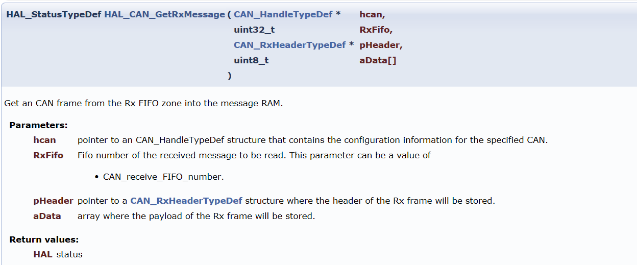
Because it's just a simple test, I set them up in the initialization phase.
Use a CAN_Config completes the function of CAN.
__IO uint32_t CAN_RxFlag = 0;		 //It is used to mark whether data is received and assign a value in the interrupt function

CAN_TxHeaderTypeDef TxMes;		//Send structure
CAN_RxHeaderTypeDef RxMes;		//Receiving structure

uint8_t CAN_TxDate[9]="CAN LOOP";								//Send buffer
uint8_t CAN_RxDate[9];								//Receive buffer

uint32_t TxMailbox;			//Hal used to indicate can message sending function_ CAN_ Which mailbox does addtxmessage use to send data


/**
  * @brief  Initialize Rx Message data structure
  * @param  RxMessage: Point to the data structure to initialize
  * @retval None
  */
void CAN_RxMesInit(CAN_RxHeaderTypeDef* RxMessage)
{

	/*Clear the receiving structure*/
  (*RxMessage).StdId = 0x00;
  (*RxMessage).ExtId = 0x00;
  (*RxMessage).IDE = CAN_ID_STD;
  (*RxMessage).DLC = 0;
  (*RxMessage).RTR = 0;
  (*RxMessage).FilterMatchIndex = 0;
	(*RxMessage).Timestamp = 0;
}

/*
 * Function name: CAN_TxMsgInit
  * @brief  Initialize TxMessage data structure
  * @param  TxMessage: Point to the data structure to initialize
  * @retval None
 */
void CAN_TxMsgInit(CAN_TxHeaderTypeDef* TxMessage)
{
  (*TxMessage).StdId=0x00;
  (*TxMessage).ExtId=0x2233;					 //Extension ID used
  (*TxMessage).IDE=CAN_ID_EXT;				  //Extended mode
  (*TxMessage).RTR=CAN_RTR_DATA;				 //Sending data
  (*TxMessage).DLC=8;							 //The data length is 8 bytes
}

/*
 * Function name: CAN_Config
 * Description: fully configure the functions of CAN
 * Input: None
 * Output: None
 * Call: MX CAN initialization call
 */
void CAN_Config(void)
{
  CAN_Filter_Config();
  CAN_TxMsgInit(&TxMes);
  CAN_RxMesInit(&RxMes);
	HAL_CAN_ActivateNotification(&hcan1,CAN_IT_RX_FIFO0_MSG_PENDING);				//Enable FIFO0 to receive data interrupt
	HAL_CAN_Start(&hcan1);		//Open CAN1
}
Call the CAN_ that you wrote in the CAN1 initialization function generated by CubeMX. Config(), complete the setting of can and turn it on.

Interrupt callback function and CAN error callback of data received by FIFO0.
/**
  * @brief  CAN Receive completion interrupt (non blocking)
  * @param  hcan: CAN Handle pointer
  * @retval nothing
  */
void HAL_CAN_RxFifo0MsgPendingCallback(CAN_HandleTypeDef* hcan)
{
	/* Is the comparison ID 0x2233 */
	HAL_CAN_GetRxMessage(&hcan1,CAN_RX_FIFO0,&RxMes,CAN_RxDate);
	if((RxMes.ExtId==0x2233) && (RxMes.IDE==CAN_ID_EXT) && (RxMes.DLC==8) )
	{
		CAN_RxFlag = 1; //Received successfully
	}
	else
	{
		CAN_RxFlag = 0; //Receive failed
	}
}
/**
  * @brief  CAN Error callback function
  * @param  hcan: CAN Handle pointer
  * @retval nothing
  */
void HAL_CAN_ErrorCallback(CAN_HandleTypeDef *hcan)
{
	printf("\r\nCAN error\r\n");
}
main function.
/* Private user code ---------------------------------------------------------*/
/* USER CODE BEGIN 0 */
extern __IO uint32_t CAN_RxFlag;		 //It is used to mark whether data is received and assign a value in the interrupt function

extern uint8_t CAN_TxDate[8];								//Send buffer
extern uint8_t CAN_RxDate[8];								//Receive buffer

extern CAN_TxHeaderTypeDef TxMes;		//Send structure
extern CAN_RxHeaderTypeDef RxMes;		//Receiving structure
extern uint32_t TxMailbox;					//Hal used to indicate can message sending function_ CAN_ Which mailbox does addtxmessage use to send data
/* USER CODE END 0 */

/**
  * @brief  The application entry point.
  * @retval int
  */
int main(void)
{
  /* USER CODE BEGIN 1 */

  /* USER CODE END 1 */

  /* MCU Configuration--------------------------------------------------------*/

  /* Reset of all peripherals, Initializes the Flash interface and the Systick. */
  HAL_Init();

  /* USER CODE BEGIN Init */

  /* USER CODE END Init */

  /* Configure the system clock */
  SystemClock_Config();

  /* USER CODE BEGIN SysInit */

  /* USER CODE END SysInit */

  /* Initialize all configured peripherals */
  MX_GPIO_Init();
  MX_USART1_UART_Init();
  MX_CAN1_Init();

  /* Initialize interrupts */
  MX_NVIC_Init();
  /* USER CODE BEGIN 2 */
	printf("CAN LOOP TEST\r\n");
	HAL_CAN_AddTxMessage(&hcan1, &TxMes, CAN_TxDate, &TxMailbox);			//send data
  /* USER CODE END 2 */

  /* Infinite loop */
  /* USER CODE BEGIN WHILE */
  while (1)
  {
    /* USER CODE END WHILE */
		if(CAN_RxFlag)
		{
			CAN_RxFlag = 0;
			printf("Transmit message:%s\r\n",CAN_TxDate);
			printf("Receive message:%s\r\n",CAN_RxDate);
		}
    /* USER CODE BEGIN 3 */
  }
  /* USER CODE END 3 */
}
effect
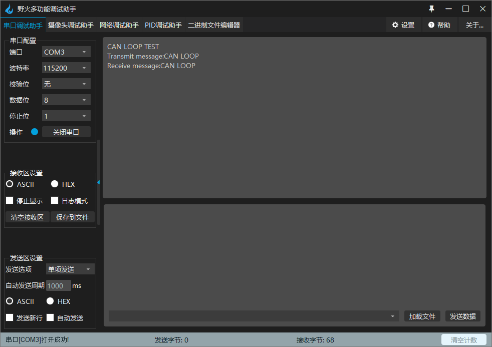
other
Initially, I set the length of the send and receive arrays to 8
uint8_t CAN_TxDate[8]="CAN LOOP";								//Send buffer
uint8_t CAN_RxDate[8];								//Receive buffer
The result is:
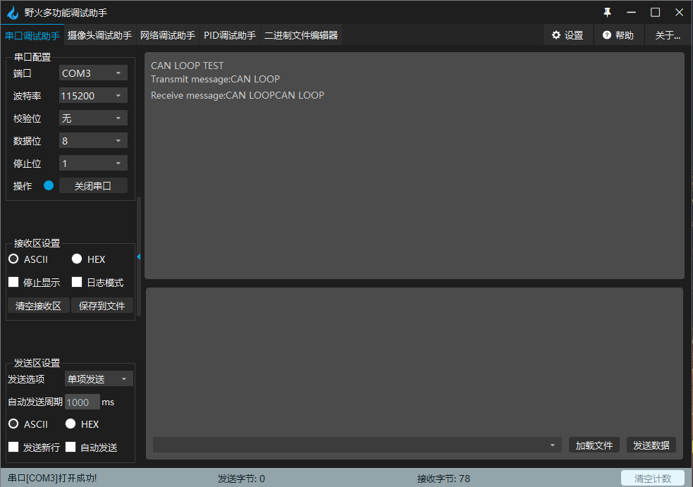
Not surprisingly, these two arrays are in memory as follows:

If it is only used to store CAN data, it is no problem, but if they are output as a character array with printf, it may cross the boundary as shown in the figure.
Therefore, I define the length of these two arrays as 9. 0 ~ 7 bytes are data, and the 8th byte is always 0 (the compiler initializes it to 0), so as to prevent printf output from crossing the boundary.