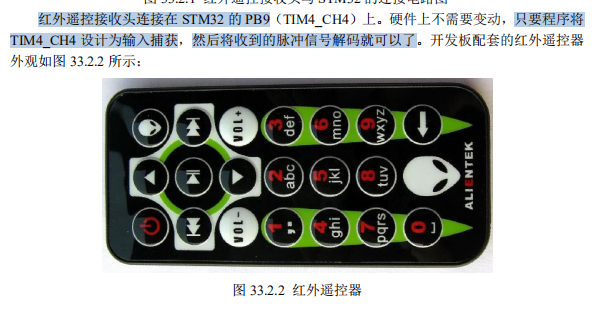
This chapter describes how to decode the signal of the infrared remote controller through STM32. The warship STMF103 is equipped with an infrared receiver and a very small infrared remote controller as standard. In this chapter, the input capture function of STM32F1 will be used to decode the code signal of the infrared remote control equipped as standard on the development board, and the decoded key value will be displayed on the TFTLCD module.
1. Introduction to infrared remote control
Infrared remote control is a kind of wireless, non-contact control technology. It has many advantages, such as strong anti-interference ability, reliable information transmission, low power consumption, low cost, easy to realize and so on. It is widely used by many electronic devices, especially household appliances, and more and more used in computer systems.
Because infrared remote control does not have the ability to control the controlled object through obstacles like radio remote control, it is not necessary to design infrared remote control like radio remote control, each set (transmitter and receiver) should have different remote control frequency or code (otherwise, the partition will control or disturb the neighbor's household appliances), so the infrared of similar products The remote controller can have the same remote control frequency or coding, without the remote control signal "serial door" situation. This provides great convenience for mass production and popularization of infrared remote control in household appliances. Because infrared is invisible light, it has little impact on the environment. The dynamic wave of infrared light is longer than the wave length of radio wave, so infrared remote control will not affect other household appliances, nor the adjacent radio equipment.
At present, the coding of infrared remote control is widely used in NEC Protocol PWM (pulse width modulation) and Philips RC-5 Protocol PPM (pulse position modulation). NEC Protocol is used for the remote control of warship STM32 development board, and its features are as follows:
- 8-bit address and 8-bit instruction length
- Address and Command 2 transfers (ensure reliability)
- PPM pulse position modulation to transmit the duty cycle of infrared carrier to represent "0" and "1"
- Carrier frequency is 38Khz
- Bit time is 1.125ms or 2.25ms
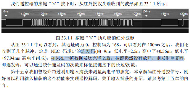
Bit definition of NEC Code: a pulse corresponds to 560us continuous carrier, a logic 1 transmission needs 2.25ms (560us pulse + 1680us low level), a logic 0 transmission needs 1.125ms (560us pulse + 560us low level). The remote control receiving head is low when receiving the pulse and high when there is no pulse. In this way, the signal we receive at the receiving head end is:
Logic 1 should be 560us low + 1680us high.
Logic 0 should be 560us low + 560us high.
The data format of NEC remote control instruction is: synchronous terminal, address code, address inverse code, control code and control inverse code.
The synchronous terminal consists of a 9ms low level and a 4.5ms high level.
Address code, address inverse code, control code and control inverse code are all 8-bit data formats. It is sent in the order of low first and high second.
The inverse code is used to increase the reliability of transmission (it can be used for verification).
2. Hardware design

3. Software design
main.c function
#include "led.h"
#include "delay.h"
#include "key.h"
#include "sys.h"
#include "lcd.h"
#include "usart.h"
#include "remote.h"

 int main(void)
 {
	u8 key;
	u8 t=0;
 	u8 *str=0;

	delay_init();	    	 //Delay function initialization
	NVIC_PriorityGroupConfig(NVIC_PriorityGroup_2);//Set interrupt priority group as group 2: 2-bit preemption priority, 2-bit response priority
	uart_init(115200);	 	//Serial port is initialized to 115200
 	LED_Init();			     //LED port initialization
	LCD_Init();
	KEY_Init();
	Remote_Init();			//Infrared receiving initialization

 	POINT_COLOR=RED;		//Set font to red
	LCD_ShowString(30,50,200,16,16,"WarShip STM32");
	LCD_ShowString(30,70,200,16,16,"REMOTE TEST");
	LCD_ShowString(30,90,200,16,16,"ATOM@ALIENTEK");
	LCD_ShowString(30,110,200,16,16,"2015/1/15");

   	LCD_ShowString(30,130,200,16,16,"KEYVAL:");
   	LCD_ShowString(30,150,200,16,16,"KEYCNT:");
   	LCD_ShowString(30,170,200,16,16,"SYMBOL:");

	while(1)
	{
		key=Remote_Scan();
		if(key)
		{
			LCD_ShowNum(86,130,key,3,16);		//Show key values
			LCD_ShowNum(86,150,RmtCnt,3,16);	//Display the number of keys
			printf("key = %d.\n",key);
			printf("RmtCnt = %d.\n",RmtCnt);

			switch(key)
			{
				case 0:str="ERROR";break;
				case 162:str="POWER";break;
				case 98:str="UP";break;
				case 2:str="PLAY";break;
				case 226:str="ALIENTEK";break;
				case 194:str="RIGHT";break;
				case 34:str="LEFT";break;
				case 224:str="VOL-";break;
				case 168:str="DOWN";break;
				case 144:str="VOL+";break;
				case 104:str="1";break;
				case 152:str="2";break;
				case 176:str="3";break;
				case 48:str="4";break;
				case 24:str="5";break;
				case 122:str="6";break;
				case 16:str="7";break;
				case 56:str="8";break;
				case 90:str="9";break;
				case 66:str="0";break;
				case 82:str="DELETE";break;
			}
			LCD_Fill(86,170,116+8*8,170+16,WHITE);	//Clear previous display
			LCD_ShowString(86,170,200,16,16,str);	//Display SYMBOL
			printf("str = %d.\n",str);
		}else delay_ms(10);
		t++;
		if(t==20)
		{
			t=0;
			LED0=!LED0;
		}
	}
}
remote.c function
#include "remote.h"
#include "delay.h"
#include "usart.h"

//Infrared remote control initialization
//Set IO and timer 4 input capture
void Remote_Init(void)
{
	GPIO_InitTypeDef GPIO_InitStructure;
	NVIC_InitTypeDef NVIC_InitStructure;
	TIM_TimeBaseInitTypeDef  TIM_TimeBaseStructure;
	TIM_ICInitTypeDef  TIM_ICInitStructure;

 	RCC_APB2PeriphClockCmd(RCC_APB2Periph_GPIOB,ENABLE); //Enable PORTB clock
	RCC_APB1PeriphClockCmd(RCC_APB1Periph_TIM4,ENABLE);	//TIM4 clock enable

	GPIO_InitStructure.GPIO_Pin = GPIO_Pin_9;		//PB9 input
 	GPIO_InitStructure.GPIO_Mode = GPIO_Mode_IPD; 	//Pull up input
 	GPIO_InitStructure.GPIO_Speed = GPIO_Speed_50MHz;
 	GPIO_Init(GPIOB, &GPIO_InitStructure);
 	GPIO_SetBits(GPIOB,GPIO_Pin_9);	//Initialize GPIOB.9


 	TIM_TimeBaseStructure.TIM_Period = 10000; //Set the counter auto reload value to max. 10ms overflow
	TIM_TimeBaseStructure.TIM_Prescaler =(72-1); //Prescaler, 1M counting frequency, 1us plus 1
	TIM_TimeBaseStructure.TIM_ClockDivision = TIM_CKD_DIV1; //Set clock split: TDTs = TK_ Tim
	TIM_TimeBaseStructure.TIM_CounterMode = TIM_CounterMode_Up; //TIM count up mode
	TIM_TimeBaseInit(TIM4, &TIM_TimeBaseStructure); //Initialize TIMx according to specified parameters

	TIM_ICInitStructure.TIM_Channel = TIM_Channel_4;  // Select input IC4 to map to TI4
	TIM_ICInitStructure.TIM_ICPolarity = TIM_ICPolarity_Rising;	//Rising edge capture
	TIM_ICInitStructure.TIM_ICSelection = TIM_ICSelection_DirectTI;
	TIM_ICInitStructure.TIM_ICPrescaler = TIM_ICPSC_DIV1;	 //Configure input frequency division without frequency division
	TIM_ICInitStructure.TIM_ICFilter = 0x03;//IC4F=0011 configure 8 input filters, timer and clock period filtering
	TIM_ICInit(TIM4, &TIM_ICInitStructure);//Initialize timer input capture channel

	TIM_Cmd(TIM4,ENABLE ); 	//Enable timer 4

	NVIC_InitStructure.NVIC_IRQChannel = TIM4_IRQn;  //TIM4 interrupt
	NVIC_InitStructure.NVIC_IRQChannelPreemptionPriority = 1;  //Priority 1
	NVIC_InitStructure.NVIC_IRQChannelSubPriority = 3;  //From priority level 3
	NVIC_InitStructure.NVIC_IRQChannelCmd = ENABLE; //IRQ channel enabled
	NVIC_Init(&NVIC_InitStructure);  //According to NVIC_ Initializes the peripheral NVIC register with the parameters specified in initstruct

	TIM_ITConfig( TIM4,TIM_IT_Update|TIM_IT_CC4,ENABLE);//Allow update interrupt, allow CC4IE to capture interrupt
}


//Remote control receiving status
//[7] : guidance code flag received
//[6] : get all the information of a key
//[5] : reserved
//[4] : mark whether the rising edge has been captured
//[3:0]: overflow timer
u8 	RmtSta=0;
u16 Dval;		//Value of counter when falling edge
u32 RmtRec=0;	//Data received by infrared
u8  RmtCnt=0;	//Number of press
//Timer 4 interrupt service routine
void TIM4_IRQHandler(void)
{

	if(TIM_GetITStatus(TIM4,TIM_IT_Update)!=RESET)
	{
		if(RmtSta&0x80)								//Last time data was received
		{
			RmtSta&=~0X10;							//Unmark rising edge has been captured
			if((RmtSta&0X0F)==0X00)RmtSta|=1<<6;	//Mark that the key value information collection of a key has been completed
			if((RmtSta&0X0F)<14)RmtSta++;
			else
			{
				RmtSta&=~(1<<7);					//Clear guide sign
				RmtSta&=0XF0;						//Clear counter
			}
		}
	}
	if(TIM_GetITStatus(TIM4,TIM_IT_CC4)!=RESET)
	{
		if(RDATA)//Rising edge capture
		{
  			TIM_OC4PolarityConfig(TIM4,TIM_ICPolarity_Falling);						//CC4P=1 set to falling edge capture
			TIM_SetCounter(TIM4,0);							//Clear timer value
			RmtSta|=0X10;							//Mark rising edge has been captured
		}else //Falling edge capture
		{
			Dval=TIM_GetCapture4(TIM4);					//Read CCR4 and clear CC4IF flag bit
  		TIM_OC4PolarityConfig(TIM4,TIM_ICPolarity_Rising);				//CC4P=0 set to rising edge capture
			if(RmtSta&0X10)							//Complete a high level acquisition
			{
 				if(RmtSta&0X80)//Guidance code received
				{

					if(Dval>300&&Dval<800)			//560 is the standard value, 560us
					{
						RmtRec<<=1;					//Move left one bit
						RmtRec|=0;					//Received 0
					}else if(Dval>1400&&Dval<1800)	//1680 is the standard value, 1680us
					{
						RmtRec<<=1;					//Move left one bit
						RmtRec|=1;					//Received 1
					}else if(Dval>2200&&Dval<2600)	//The information 2500 of key value increase is the standard value of 2.5ms
					{
						RmtCnt++; 					//Press the key once more
						RmtSta&=0XF0;				//Clear timer
					}
 				}else if(Dval>4200&&Dval<4700)		//4500 is the standard value of 4.5ms
				{
					RmtSta|=1<<7;					//Tag successfully received the boot code
					RmtCnt=0;						//Clear key count
				}
			}
			RmtSta&=~(1<<4);
		}
	}
	TIM_ClearITPendingBit(TIM4,TIM_IT_Update|TIM_IT_CC4);
}

//Process infrared keyboard
//Return value:
//	 0, no key pressed
//Other, press the key value
u8 Remote_Scan(void)
{
	u8 sta=0;
    u8 t1,t2;
	if(RmtSta&(1<<6))//Got all the information for one button
	{
	    t1=RmtRec>>24;			//Get the address code
	    t2=(RmtRec>>16)&0xff;	//Get address inverse
 	    if((t1==(u8)~t2)&&t1==REMOTE_ID)//Verify remote ID and address
	    {
	        t1=RmtRec>>8;
	        t2=RmtRec;
	        if(t1==(u8)~t2)sta=t1;//Correct key value
		}
		if((sta==0)||((RmtSta&0X80)==0))//Key data error / remote control has not been pressed
		{
		 	RmtSta&=~(1<<6);//Clear valid key ID received
			RmtCnt=0;		//Clear key count
		}
	}
    return sta;
}
remote.h file
#ifndef __RED_H
#define __RED_H
#include "sys.h"

#define RDATA 	PBin(9)	 	//Infrared data input pin

//Infrared remote control identification code (ID), the value of each remote control is basically different, but also the same
//Our remote control ID is 0
#define REMOTE_ID 0

extern u8 RmtCnt;			//Number of press

void Remote_Init(void);    	//Infrared sensor receiving head pin initialization
u8 Remote_Scan(void);
#endif
In the interrupt processing program of timer 4, the infrared signal is decoded and the decoded data is saved, and the decoded data is transmitted in the infrared scanning function. Therefore, the key value pressed by the remote controller can be known only if the infrared scanning function is invoked in the main function.