1.SPI protocol
SPI is the abbreviation of Serial Peripheral Interface. It is a high-speed, full duplex and synchronous communication bus, and only occupies four wires on the pins of the chip. They are the following four
- MISO – Master Input Slave Output, master equipment data input and slave equipment data output;
- MOSI – Master Output Slave Input, master device data output, slave device data input;
- SCLK – Serial Clock, clock signal, generated by the master equipment;
- CS – Chip Select, enabling signal of slave device, controlled by master device.
1.1 four modes of SPI
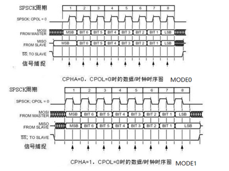
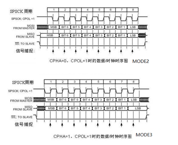
The four modes of spi are determined by setting 0 and 1 for CPOL and CPHA. Arrange and combine 4 types:
Cpol: clock signal level when SPI is idle (1: high level, 0: low level)
CPHA: SPI samples at the first edge of the clock (1: start at the second edge, 0: start at the first edge)
Then, in STM32, it is embodied in this structure (omitted):
typedef struct
{
......
  uint16_t SPI_CPOL;                /*!< Specifies the serial clock steady state.
                                        This parameter can be a value of @ref SPI_Clock_Polarity */
  uint16_t SPI_CPHA;                /*!< Specifies the clock active edge for the bit capture.
......
}SPI_InitTypeDef;
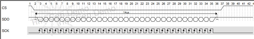
It needs to be configured according to the datasheet of the slave station, such as the following sequence diagram:
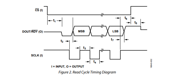
SCLK defaults to high level and collects data bits from the second edge of sck, so:
CPOL=1;
CPHA=1;
2. STM32F103 hardware SPI
The SPI - > Dr register of STMf103 is 16 bits. From the reference manual, F1 chip supports 8-bit and 16 bit data transmission. The DFF flag bit of SPI - > CR1 determines whether the transmitted data is 8 bits or 16 bits. This is also determined by referring to the datasheet of the slave station. Main mode baud rate prescaled coefficient (maximum fPCLK/2), so SPI can be divided into a frequency of 36MHz at most. For SPI sending function, the standard library function version and HAL library provide two solutions:
2.1 sending function of standard library
/**
  * @brief  Transmits a Data through the SPIx/I2Sx peripheral.
  * @param  SPIx: where x can be
  *   - 1, 2 or 3 in SPI mode
  *   - 2 or 3 in I2S mode
  * @param  Data : Data to be transmitted.
  * @retval None
  */
void SPI_I2S_SendData(SPI_TypeDef* SPIx, uint16_t Data)
{
  /* Check the parameters */
  assert_param(IS_SPI_ALL_PERIPH(SPIx));

  /* Write in the DR register the data to be sent */
  SPIx->DR = Data;
}
assert_ The assertion param can be ignored. In fact, it means that the data is written to the DR register without any judgment. Therefore, we usually jump out of timeout when using and detect whether the transmission is successful, as follows:
while (SPI_I2S_GetFlagStatus(SPI2, SPI_I2S_FLAG_TXE) == RESET) //Check whether the specified SPI flag bit is set or not: send cache empty flag bit
		{
		retry++;
		if(retry>200)return 0;//Retry 200 times
		}
But execute retry + + and SPI_I2S_GetFlagStatus(SPI2, SPI_I2S_FLAG_TXE) == RESET takes CPU time, which will cause discontinuous transmission of SPI during transmission. See details for details 3. Section.
2.2 HAL library sending function
The sending function of HAL library is relatively long. I deleted it here and only looked at the 8-bit sending process.
HAL_StatusTypeDef HAL_SPI_Transmit(SPI_HandleTypeDef *hspi, uint8_t *pData, uint16_t Size, uint32_t Timeout)
{
	.......
	  /* Set the transaction information */
 	hspi->State       = HAL_SPI_STATE_BUSY_TX;
  	hspi->ErrorCode   = HAL_SPI_ERROR_NONE;
 	hspi->pTxBuffPtr  = (uint8_t *)pData;
  	hspi->TxXferSize  = Size;
  	hspi->TxXferCount = Size;
  	.......
    while (hspi->TxXferCount > 0U)
    {
      /* Wait until TXE flag is set to send data */
      if (__HAL_SPI_GET_FLAG(hspi, SPI_FLAG_TXE))
      {
        *((__IO uint8_t *)&hspi->Instance->DR) = (*hspi->pTxBuffPtr);
        hspi->pTxBuffPtr += sizeof(uint8_t);
        hspi->TxXferCount--;
      }
      else
      {
        /* Timeout management */
        if ((((HAL_GetTick() - tickstart) >=  Timeout) && (Timeout != HAL_MAX_DELAY)) || (Timeout == 0U))
        {
          errorcode = HAL_TIMEOUT;
          goto error;
        }
      }
    }

}
Core part:
if (__HAL_SPI_GET_FLAG(hspi, SPI_FLAG_TXE))
   *((__IO uint8_t *)&hspi->Instance->DR) = (*hspi->pTxBuffPtr);
It also checks the transmission completion flag bit and writes the data to the DR register. But the HAL library is better written because it supports writing data length. Generally, we don't write only 8 bits. Generally, an instruction has 32 bits or more. For the encapsulation of HAL library, I only need to provide a first address and set the Size to the corresponding length. Click jump
2.2.1 there is a small pit here
The data stored in the single chip microcomputer is stored in the small end format, but the data is often sent in the large end format.
For example, I want to send 01 02 03 04
But we can easily save:
uint32_t data =0x01020304
Then point * pData to the address of data, and the data sent through SPI will become 04 03 02 01. Therefore, software is required for large end and small end conversion.
3. Continuous and discontinuous transmission of SPI
Preconditions: 8-bit spi transmission is set here. Let's look at the difference between the time sequence diagram of transmitting 32-bit data:
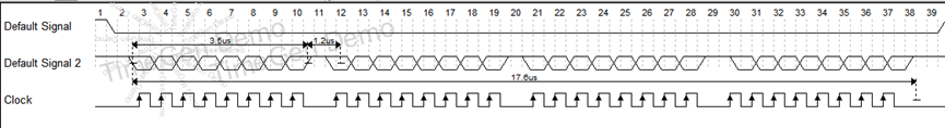
When transmitting data in the main mode, if the software is fast enough, it can detect the rising edge of each TXE (or TXE interrupt) and write the SPI immediately before the end of the ongoing transmission_ Dr register can realize continuous communication; At this time, the SPI clock between the transmission of each data item remains continuous, and the BSY bit is not cleared. If the software is not fast enough, it will lead to discontinuous communication; At this time, it will be cleared between each data transmission
From this description, as long as you write data fast enough, it can be transmitted continuously. This is obviously unreliable. The faster the SPI speed, the faster the software writing speed will not keep up. So how to give full play to the performance of ST hardware SPI? Turn on DMA mode.
3.SPI+DMA transmission
Select DMA configuration according to your SPI channel and use STM32Cube for configuration
This is a transmission function I wrote, but it is found that the transmitted data is wrong when grasping the waveform, but it is normal to send without DMA. Later, it took a long time to find the problem.
int sgm5349_RegWrite(sgm5349Device_t *device, uint8_t channel, uint16_t data, uint8_t update){
HAL_StatusTypeDef status = HAL_OK;
uint32_t regVal = 0;
/* Input Validation Check */
if(device == NULL) return -1;
if(isChannelValid(channel) != 0) return -1;
/* 32bit register value generation with command = 0 or 2 or 3*/
regVal = (channel << 20) | (data << 4);
if(update == 1) regVal |= (3 << 24);
else if(update == 2) regVal |= (2 << 24);
regVal = LittleEndian2BigEndian(regVal);
HAL_GPIO_WritePin(GPIOA,GPIO_PIN_3,0);
HAL_SPI_Transmit_DMA(device->hspi, (uint8_t *)®Val, 4);
HAL_GPIO_WritePin(GPIOA,GPIO_PIN_3,1);
if(status != HAL_OK) return (int)status;
return 0;
}
The DMA transmission code is as follows (partially omitted):
HAL_StatusTypeDef HAL_SPI_Transmit_DMA(SPI_HandleTypeDef *hspi, uint8_t *pData, uint16_t Size)
{
......
  /* Set the transaction information */
  hspi->State       = HAL_SPI_STATE_BUSY_TX;
  hspi->ErrorCode   = HAL_SPI_ERROR_NONE;
  hspi->pTxBuffPtr  = (uint8_t *)pData;
  hspi->TxXferSize  = Size;
  hspi->TxXferCount = Size;
/* Enable the Tx DMA Stream/Channel */
  if (HAL_OK != HAL_DMA_Start_IT(hspi->hdmatx, (uint32_t)hspi->pTxBuffPtr, (uint32_t)&hspi->Instance->DR,
                                 hspi->TxXferCount))
  {
    /* Update SPI error code */
    SET_BIT(hspi->ErrorCode, HAL_SPI_ERROR_DMA);
    errorcode = HAL_ERROR;

    hspi->State = HAL_SPI_STATE_READY;
    goto error;
  }
 ......
}
The problem is that in the DMA sending function, (uint32_t) hspi - > ptxbuffptr is forcibly converted to the address of the data. But we brought in HAL_SPI_Transmit_DMA is a local variable regVal. When you jump out of sgm5349_ When regwrite function, the local variable will release regVal, so the address of this local variable is meaningless. So a simple test and a delay can send data normally. Of course, we can't do this in practice. We can solve this problem by adding local variable + static modification, or allowing the program to send the completion flag bit through query.
Finally, a complete continuous SPI data transmission is obtained