1, W5500 module
1. Introduction to w5500 Ethernet module
(1)D-W5500 EVB Ethernet module is an Ethernet module based on WIZnet W5500 chip with high cost performance. W5500 is a full hardware TCP/IP embedded Ethernet controller, which provides a more recommended Internet connection scheme for embedded systems.
(2)W5500 solidifies the TCP/IP protocol stack, 10/100Mbps Ethernet data link layer (MAC) and physical layer (PHY) enable users to expand network connection in their applications by using a single chip. 32K byte on-chip cache is embedded for Ethernet processing, and 8 hardware sockets can be used for independent communication at the same time; SPI (peripheral ship interface) can be more easily integrated with peripheral MCU, Moreover, w5500 uses efficient SPI protocol to support 80MHz, so as to realize high-speed network communication.
(3) The module also supports 3.3V or 5V power supply. When 5V power supply, it can also output 3.3V voltage, which is convenient for users to use in different single chip microcomputer systems.
2. Module needle arrangement function table
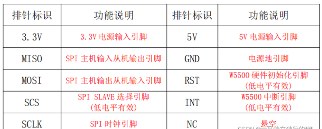
Line connection method
PA3 -> W5500_RST
PA4 -> W5500_SCS
PA5 -> W5500_SCK
PA6 -> W5500_MISO
PA7 -> W5500_MOSI
2, modbus Protocol
1.modbus protocol principle
Modbus protocol is a general communication protocol which has been widely used in today's industrial control field. Through this protocol, the controllers Or controller via network (such as Ethernet) can communicate with other devices. Modbus protocol uses master-slave communication technology, that is, the master device actively queries and operates the slave device. Generally, the protocol used by the master device is called Modbus Master, and the protocol used by the slave device is called Modbus Slave. Typical master devices include industrial computers and industrial controllers; typical slave devices such as PLC can Programmable controller, etc.
The physical interface of Modbus communication can be serial port (including RS232, RS485 and RS422) or Ethernet port. Its communication follows the following process:
The master device sends a request to the slave device
The slave device analyzes and processes the request of the master device, and then sends the result to the master device
If any error occurs, the slave device will return an abnormal function code
Modbus works in the mode of request / response. The master station sends instructions first for each communication, which can be broadcast or unicast to a specific slave station; The slave station responds to the command and responds as required, or reports an exception. When the master station does not send a request, the slave station will not send data by itself, and there is no direct communication between the slave station and the slave station.
Modbus protocol is an application layer (protocol layer) message transmission protocol. It defines a protocol data unit (PDU) independent of the physical layer, that is, PDU = function code + data field, function code 1byte, and the data field is uncertain.
Modbus protocol can be applied to different types of buses or networks. Corresponding to different buses or networks, MODBUS protocol introduces some additional domains to map into application data unit (ADU), that is, ADU = additional domain + PDU, for example, modbus tcp/ip------ ADU=MBAP+ADU.
2.Modbus communication mode
Three Modbus communication modes
Modbus has the following three communication modes:
(1) Ethernet: the corresponding communication mode is Modbus TCP/IP
(2) Asynchronous serial transmission (various media such as wired RS-232-/422/485 /; optical fiber, wireless, etc.): the corresponding communication mode is Modbus RTU or Modbus ASCII
(3) High speed token passing network: the corresponding communication mode is Modbus PLUS
Modbus RTU and Modbus ASCII Protocol shall be used for serial port link (RS232, RS485, RS422), and Modbus tcp/ip Protocol shall be used for Ethernet link.
2. Transmission on Modbus network
The standard Modbus port uses RS-232C compatible serial interface, which defines the pin, cable, signal bit, transmission baud rate and parity of the connection port. The controller can network directly or via Modem.
The controller communication uses master / slave technology, that is, only one device (master device) can initialize transmission (query). Other devices (slave devices) respond accordingly according to the data provided by the master device.
Typical main equipment: host and programmable instrument.
Typical slave device: programmable controller.
The master device can communicate with the slave device alone or with all the slave devices by broadcasting. In case of separate communication, a message is returned from the device as a response. If it is queried by broadcast, no response is made.
Modbus protocol establishes the format of master device query: device (or broadcast) address, function code, all data to be sent, and an error detection domain.
The slave device response message is also composed of Modbus protocol, including confirming the domain to be acted on, any data to be returned, and an error detection domain. If an error occurs during message reception, or the slave device cannot execute its command, the slave device will establish an error message and send it as a response.
3. Ethernet (modbus tcp/ip)
For Modbus TCP, the Master station is usually called Client and the Slave station is called Server; For Modbus RTU and Modbus ASCII, the Master station is Master and the Slave station is Slave.
The data frame of ModbusTCP can be divided into two parts: ADU=MBAP+PDU = MBAP + function code + data field, MBAP 7byte and function code 1byte. The data field is uncertain and determined by the specific function.
3, Code implementation
1. Initialize the slave network
void Load_Net_Parameters(void)
{
	Gateway_IP[0] = 192;//Load gateway parameters
	Gateway_IP[1] = 168;
	Gateway_IP[2] = 1;
	Gateway_IP[3] = 1;

	Sub_Mask[0]=255;//Load subnet mask
	Sub_Mask[1]=255;
	Sub_Mask[2]=255;
	Sub_Mask[3]=0;

	Phy_Addr[0]=0x0c;//Load physical address
	Phy_Addr[1]=0x29;
	Phy_Addr[2]=0xab;
	Phy_Addr[3]=0x7c;
	Phy_Addr[4]=0x00;
	Phy_Addr[5]=0x01;

	IP_Addr[0]=192;//Load native IP address
	IP_Addr[1]=168;
	IP_Addr[2]=1;
	IP_Addr[3]=199;

	S0_Port[0] = 0x13;//Load port number 5000 for port 0
	S0_Port[1] = 0x88;

	S0_Mode=TCP_SERVER;//Load the working mode of port 0, TCP server mode
2. Response function
void Process_Socket_Data(SOCKET s)
{
	int len;
	unsigned char msg[11]={0x00,0x00,0x00 ,0x00, 0x00, 0x05, 0x01, 0x03, 0x02, 0x00, 0x70};
	len=sizeof(msg);
	unsigned short size;
	size=Read_SOCK_Data_Buffer(s, Rx_Buffer);
	memcpy(Tx_Buffer, Rx_Buffer, size);

	//Print query message
	for (int j=0;j<size;j++){
		 printf("0x%02X ",Tx_Buffer[j]);
	}

	//Write response message
	//Inspection code
	msg[0]=Tx_Buffer[0];
	msg[1]=Tx_Buffer[1];

	//agreement
	msg[2]=0x00;
	msg[3]=0x00;

	//Packet length
	msg[4]=0x00;
	msg[5]=0x05;

	//Equipment number
	msg[6]=Tx_Buffer[6];
	//Function code
	msg[7]=Tx_Buffer[7];
	//Data length
	msg[8]=0x02;

	//Lower eight
	msg[10]=data&0XFF;
	//High eight
	msg[9]=data>>8;

	memcpy(Tx_Buffer, msg, len);
	//Send response message
	Write_SOCK_Data_Buffer(0, Tx_Buffer, len);
	data++;
}
3. The main function loops and waits for the connection
 while (1)
  {
		W5500_Socket_Set();//W5500 port initialization configuration

		W5500_Interrupt_Process();//W5500 interrupt handler framework

		if((S0_Data & S_RECEIVE) == S_RECEIVE)//If Socket0 receives data
		{
			S0_Data&=~S_RECEIVE;
			Process_Socket_Data(0);//The W5500 receives and sends the received data
		}
		//Slave status flag
		HAL_GPIO_TogglePin(GPIOC,GPIO_PIN_13);
  }
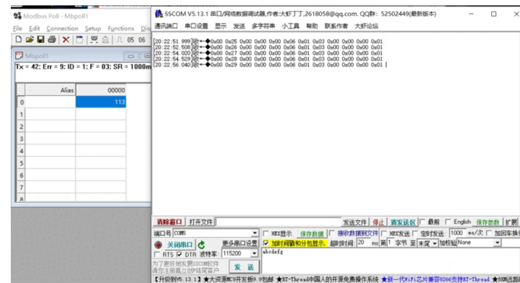
4, Results
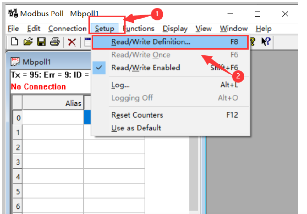
1. Establish connection with MODBUS poll
Set id, address and read digit
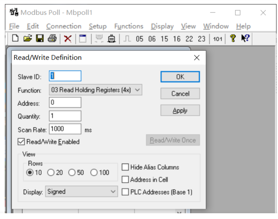
TCP/IP establishes a connection and sets the address and port
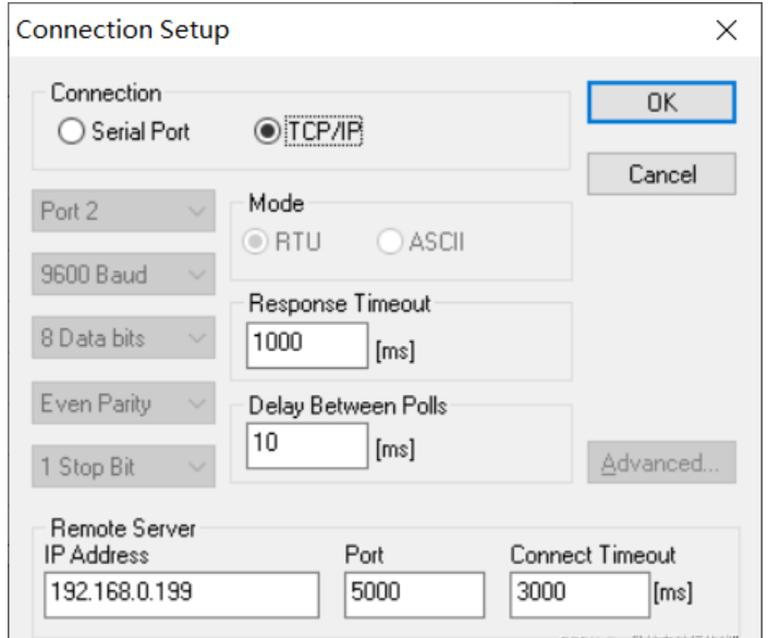
The connection succeeded as follows

The effect is as follows