I haven't found anything useful for a long time, so I transplanted the HAL library myself. Now share it
The price of the screen has increased a lot recently, In order to be cheap, I bought a 1.8-inch touch-free TFT (ST7735) screen at a treasure for 23. After buying it, I found that it was slightly different from others. I didn't see relevant references on the Internet. There were only a few routines given by the store, but the pin definitions in the routines were different from those I got. I couldn't control the backlight. What I got was the following screen
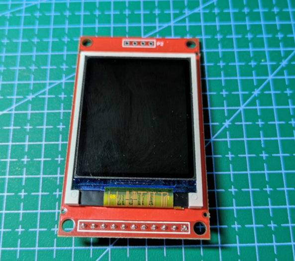
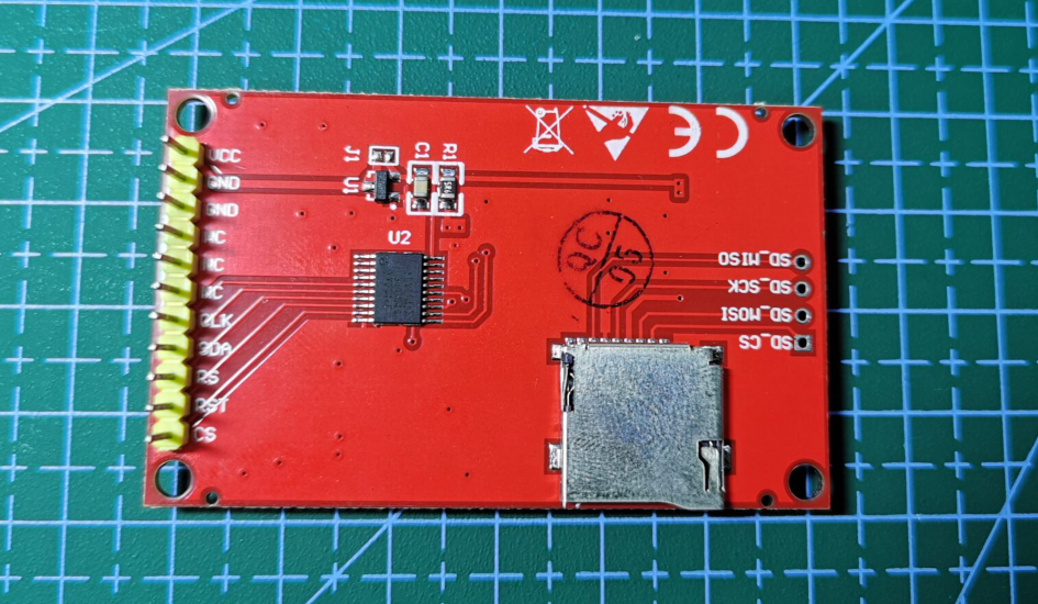
It can be seen that there are only five effective pins CLK, SDA (MOSI), RS, RST and CS, and there is less to control the backlight LED pin. However, this is not a big problem. Because other functions of the project are developed using HAL library, we can only change the driver routine of STM32F103 firmware library and transplant it to STM32F407HAL library.
catalogue
hardware platform
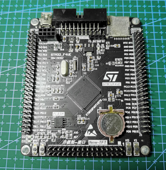
The hardware platform used this time is STM32F407VET6 core board
The software uses keil 5 35 and STM32CubeMX
Wiring mode
- VCC # 3.3V (5V is easy to burn the screen)
- GND GND
- GND GND
- NC = suspended
- NC = suspended
- NC = suspended
- CLK PD0
- SDA/MOSI PD1
- RS/DC PD2
- RST/RES PD3
- CS/CE PD4
STM32CubeMX configuration
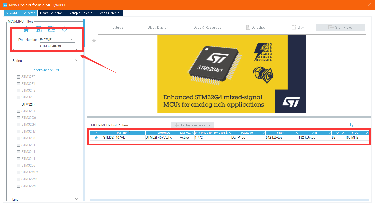
Step 1: select the chip:
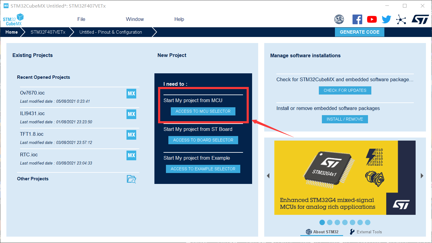
Then find the chip model on your development board (I recommend that you click which star to collect the chip model on your development board. Next time, you can directly click the favorite next to the search box)
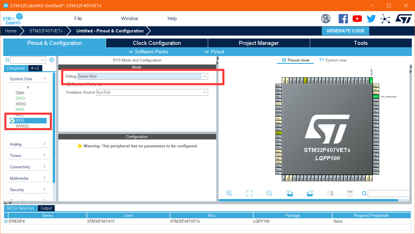
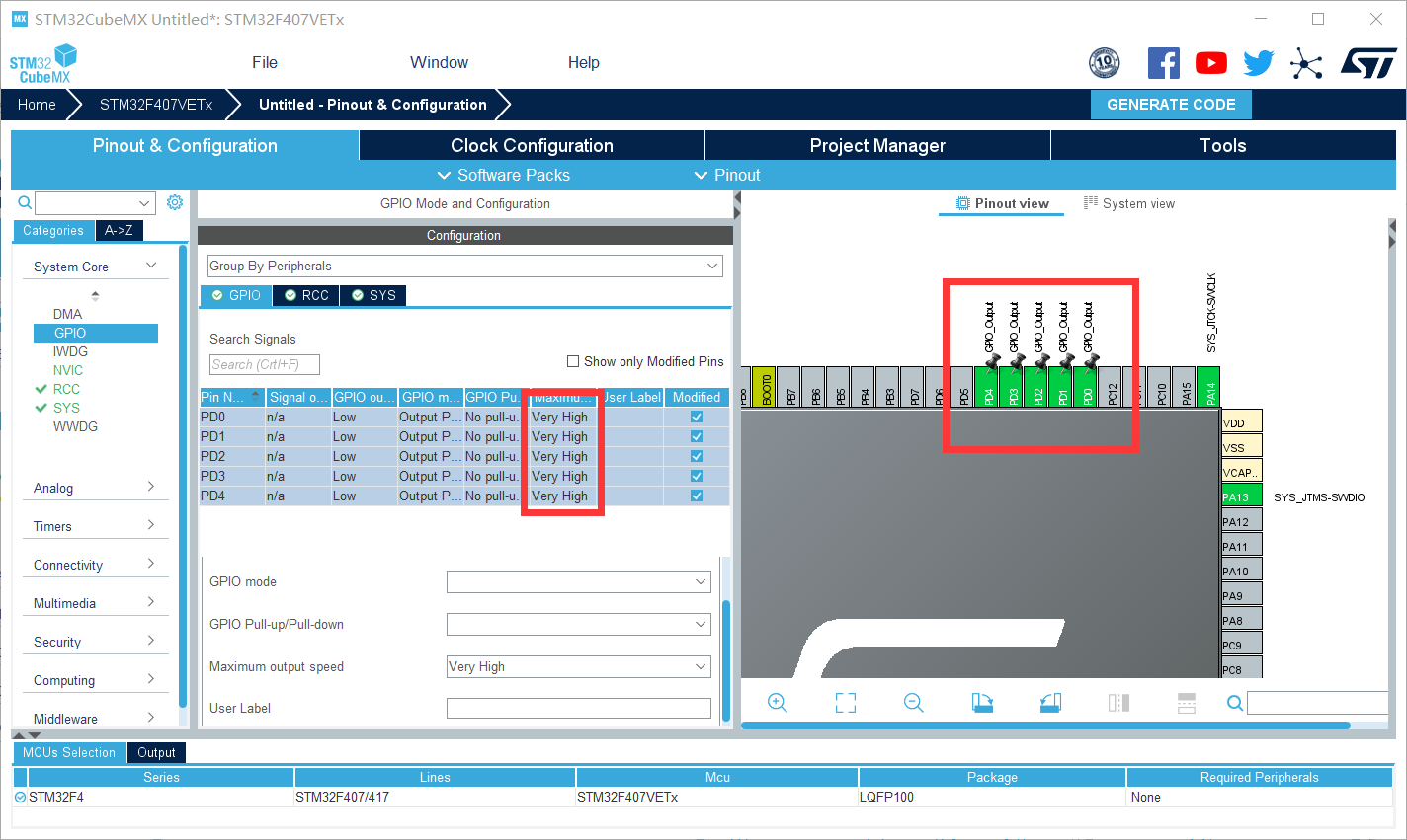
Step 2 start debugging (prevent the chip from locking) and configure the IO port
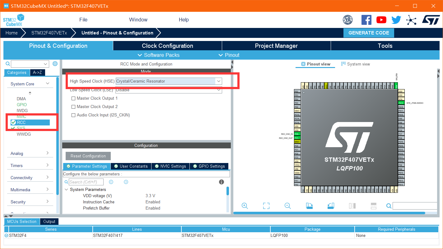
Select use external high speed clock
Configure IO
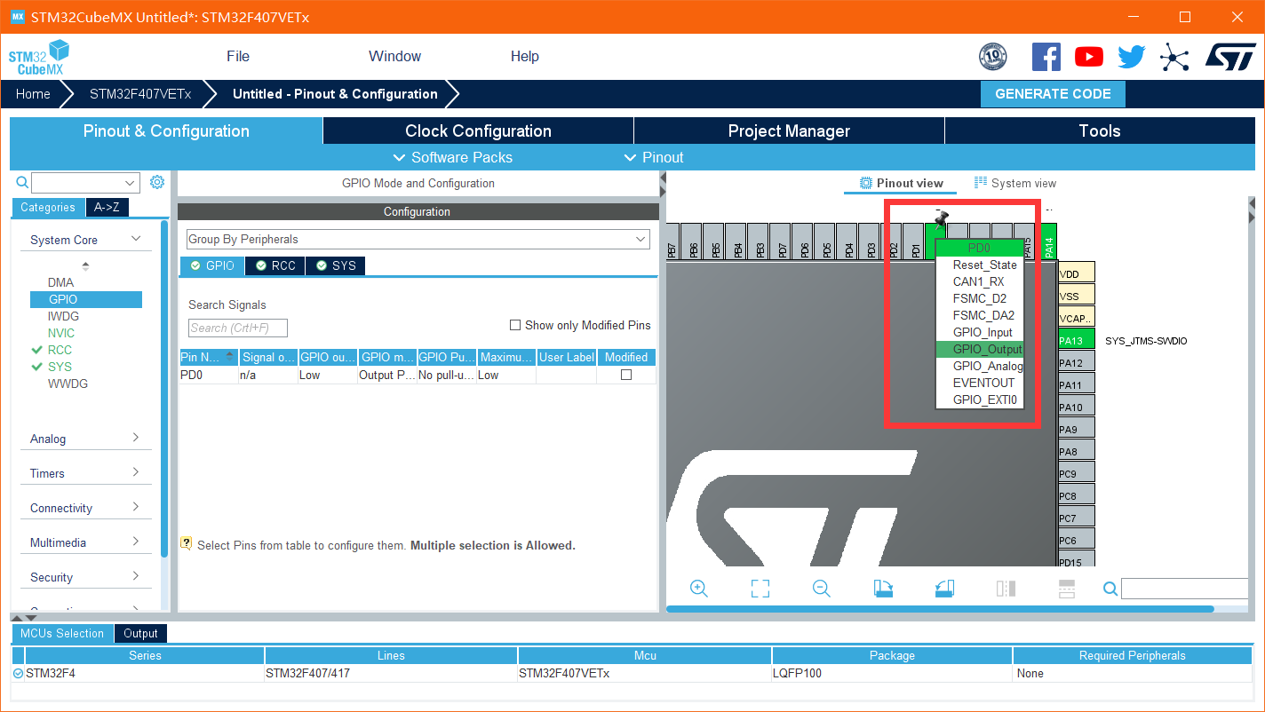
The following four configurations are the same: no pull-down, push-pull output, and turn the IO rate to the highest very high (to make the screen refresh faster)
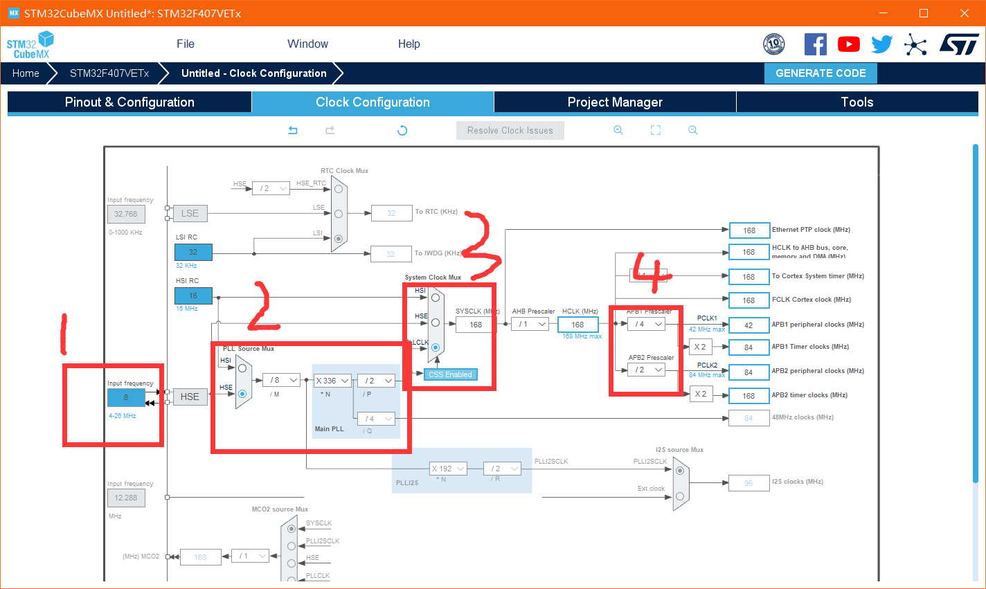
Step 3 configure the clock
Because the board is equipped with 8M crystal oscillator, it needs to be changed. cubemx defaults to 25M crystal oscillator
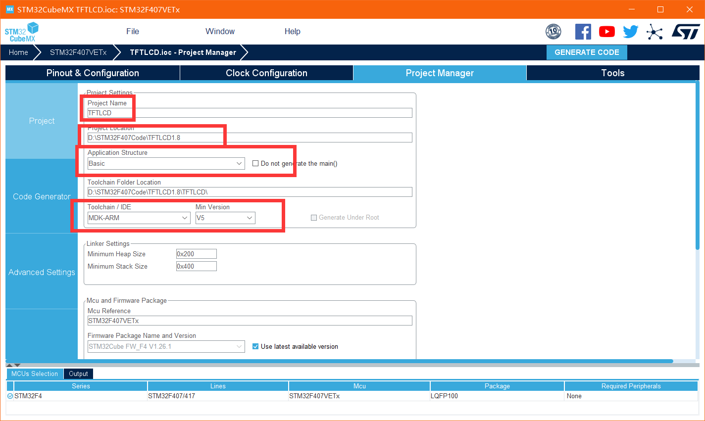
Step 4 set project configuration
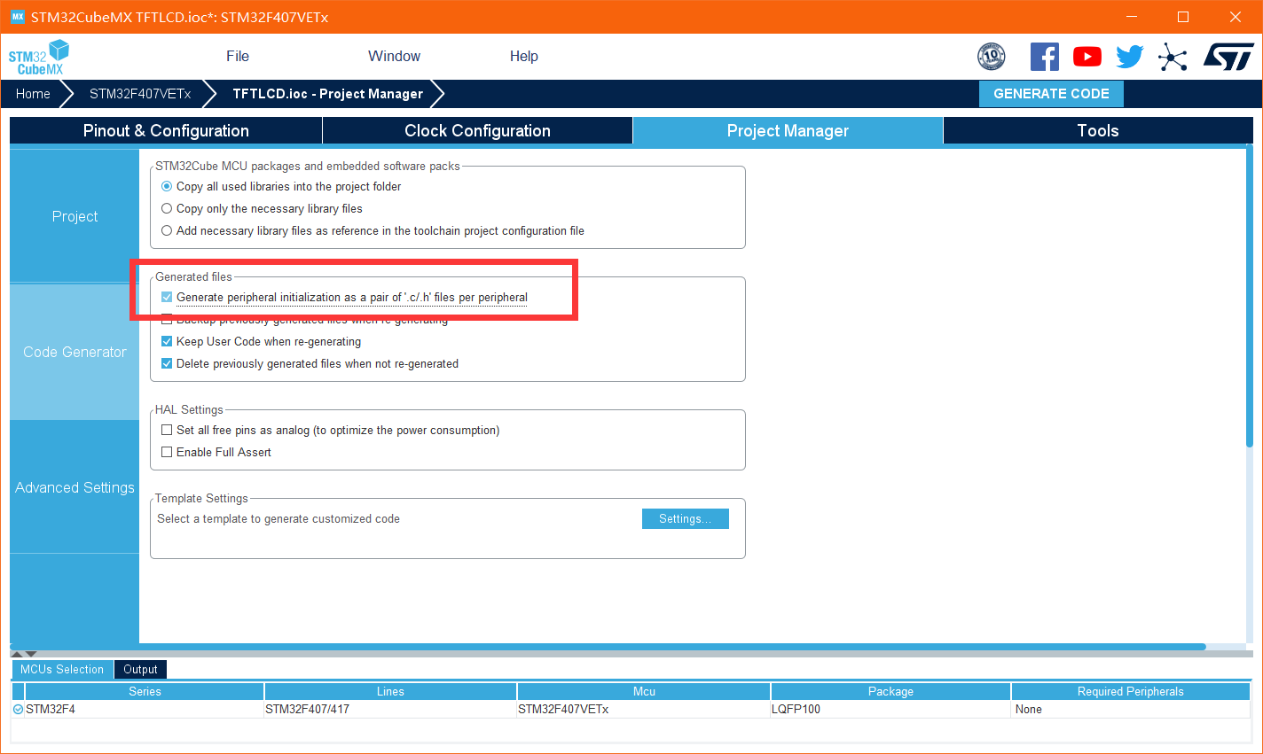
The last step is to generate the code
Mr. Cheng reports and gets an ioc file of cubemx. You can continue to configure it later
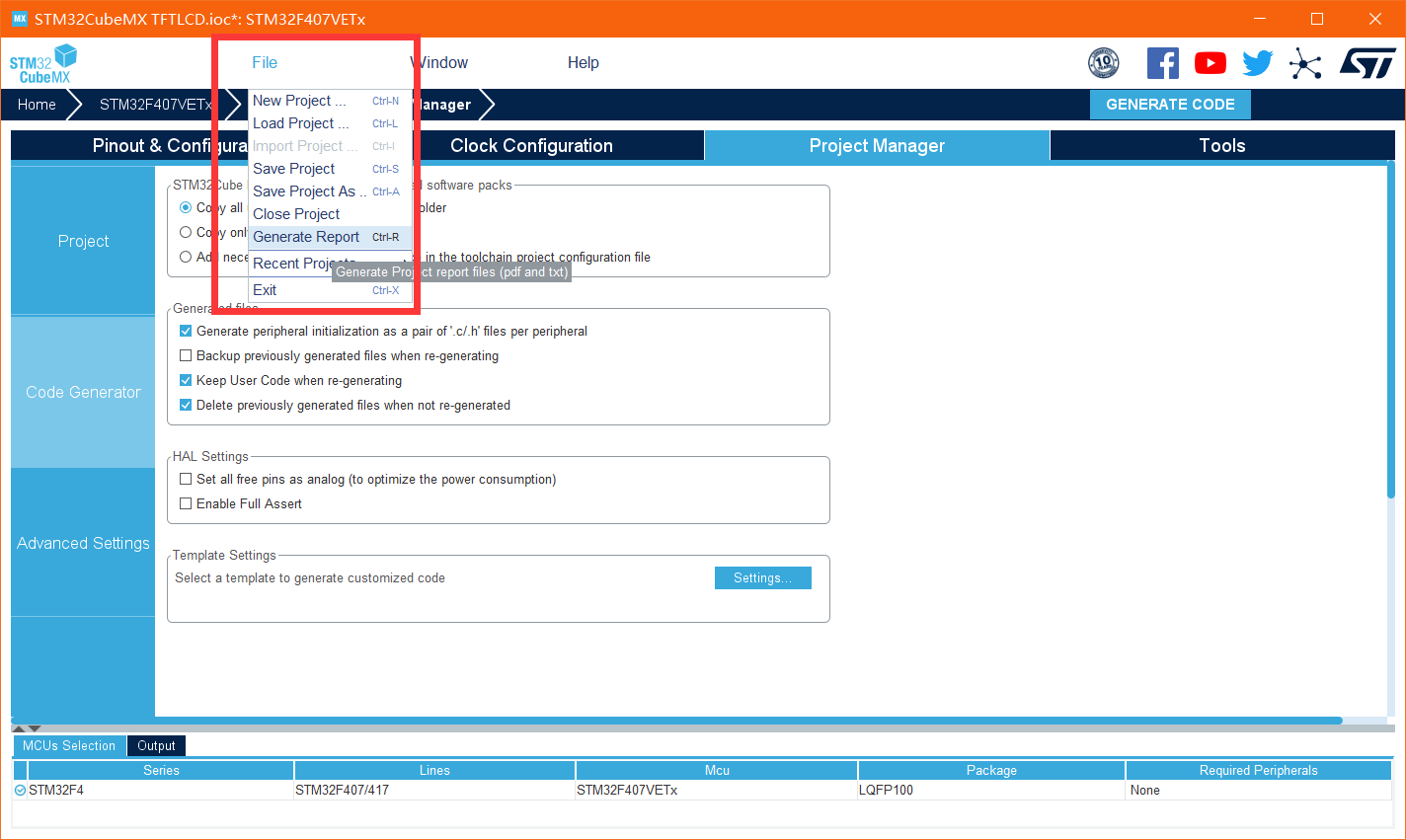
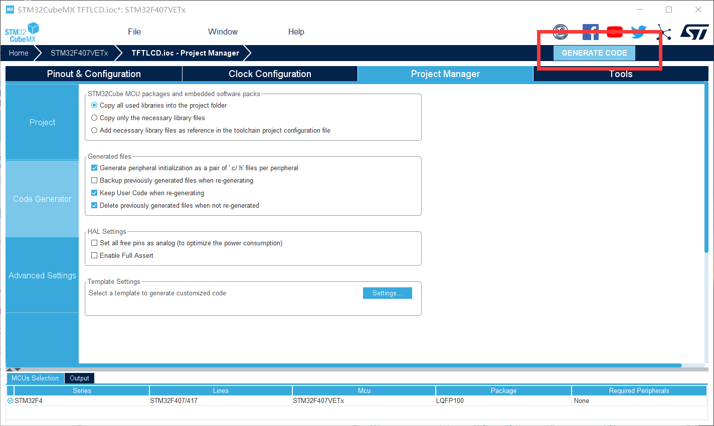
Then click the generate code in the upper right corner (the path of the generated code cannot exist in Chinese, otherwise the generated code will fail)
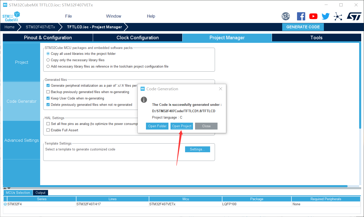
After successful generation, directly click to open the project
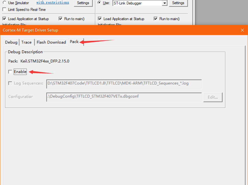
Open the project and configure it for download
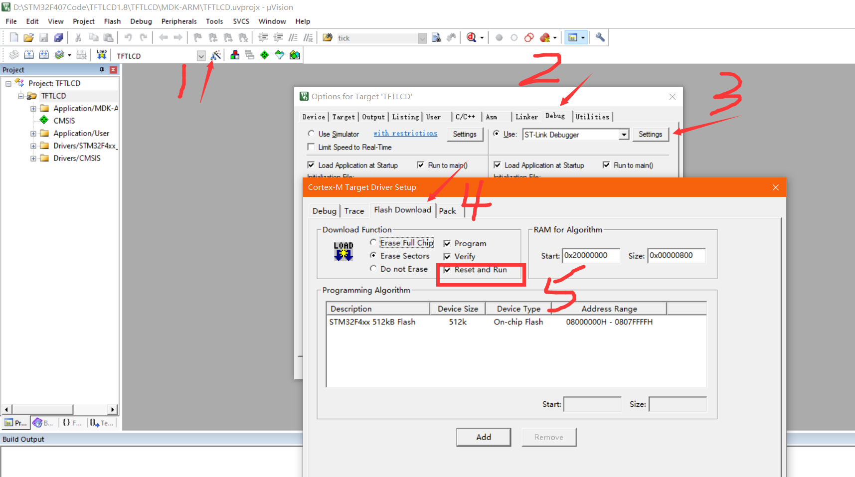
Then select pack to cancel (to prevent the operation from being reset after downloading)
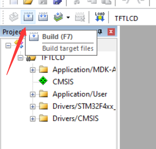
After completion, compile the project first
Then go back to the project directory and create a file to install the migrated program
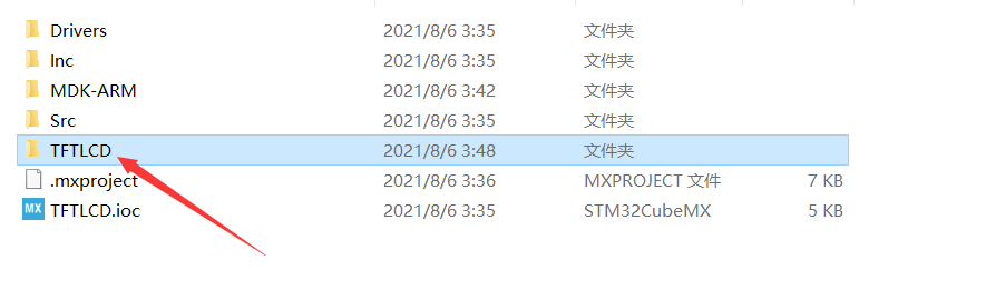
Open the program that contains the transplant
Go back to keil and order this
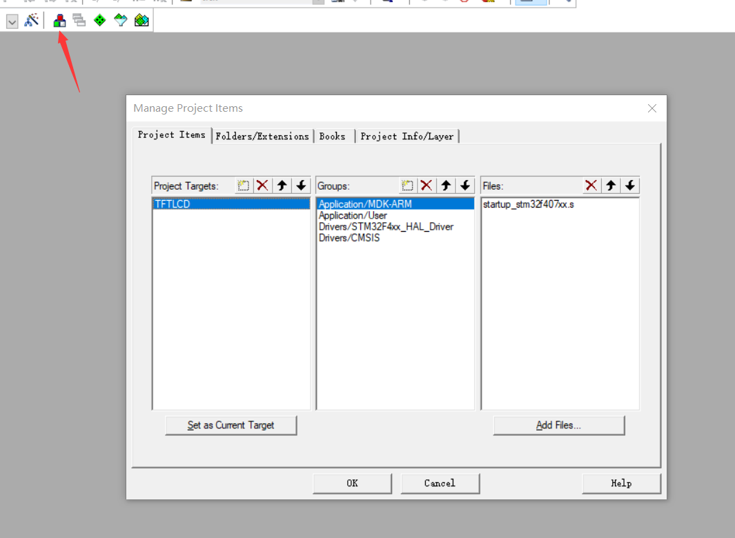
Then create a new one
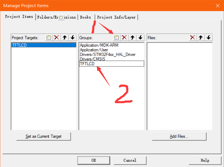
Select the new key to add files to it
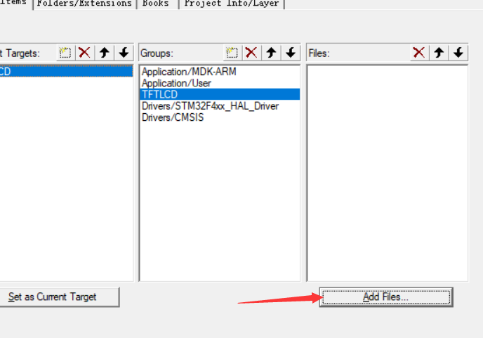
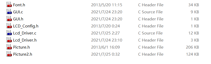
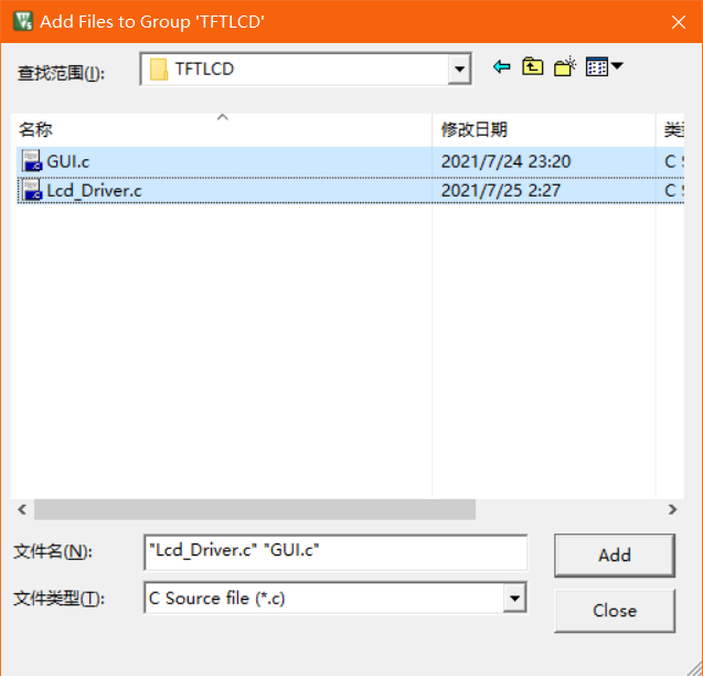
Find the C file just migrated, add it, and click ok
Then add the header file directory
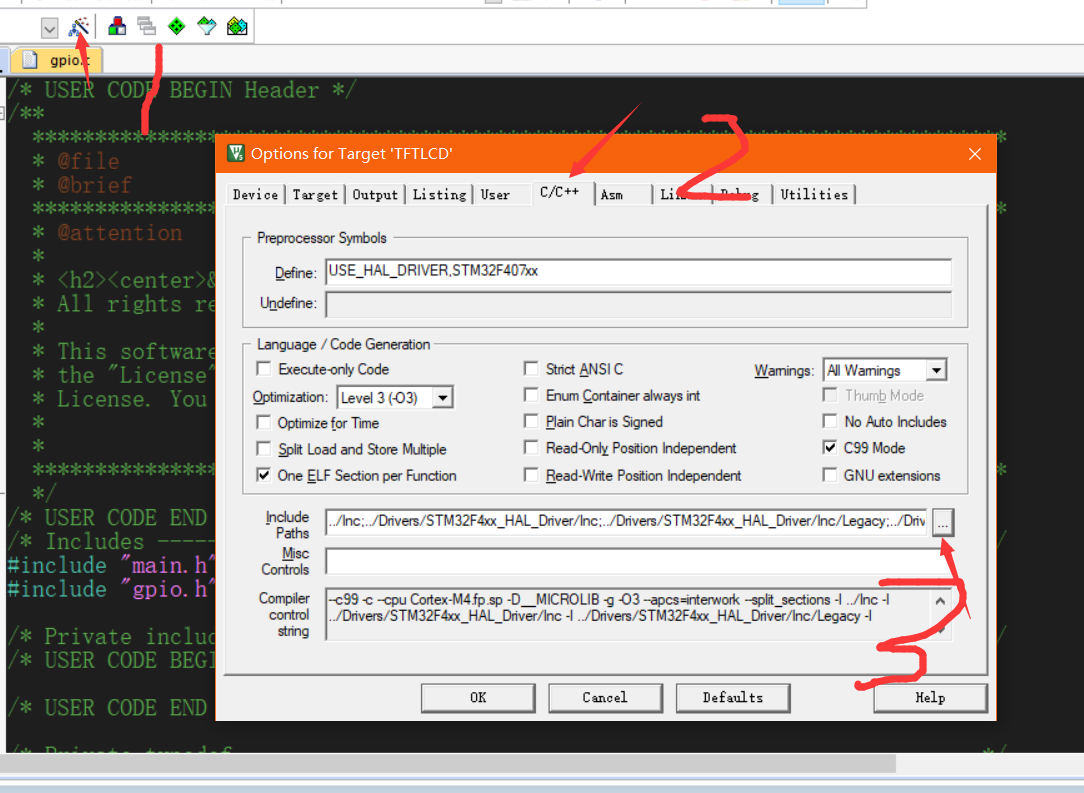
Then create a new path and click the sequence number next to it to select the header file path
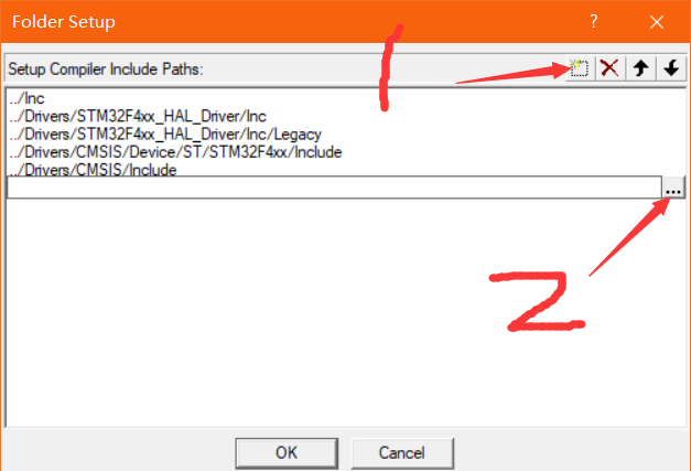
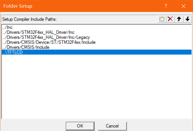
Then click ok
Here, most of the migration process has been completed, and the next step is to change the code
Code part
Lcd_ Driver. H (partial code)
#include "stm32f4xx_hal.h"
#include "stm32f407xx.h"

#define RED  	0xf800
#define GREEN	0x07e0
#define BLUE 	0x001f
#define WHITE	0xffff
#define BLACK	0x0000
#define YELLOW  0xFFE0
#define GRAY0   0xEF7D    	// Gray 0 3165 00110 001011 00101
#define GRAY1   0x8410       	// Grey 1 00000 000000 00000
#define GRAY2   0x4208       	// Grey 2 1111111111011111


#define LCD_CTRL    	  	 GPIOD 		// Define TFT data port
#define LCD_RS         	GPIO_PIN_2	//TFT --RS/DC
#define LCD_CS        	GPIO_PIN_4  //TFT --CS/CE
#define LCD_RST     		GPIO_PIN_3	//TFT --RST
#define LCD_SCL        	GPIO_PIN_0	//TFT --SCL/SCK
#define LCD_SDA        	GPIO_PIN_1	//TFT --SDA/DIN


#define	LCD_CS_SET  	LCD_CTRL->BSRR=LCD_CS
#define	LCD_RS_SET  	LCD_CTRL->BSRR=LCD_RS
#define	LCD_SDA_SET  	LCD_CTRL->BSRR=LCD_SDA
#define	LCD_SCL_SET  	LCD_CTRL->BSRR=LCD_SCL
#define	LCD_RST_SET  	LCD_CTRL->BSRR=LCD_RST
#define	LCD_LED_SET  	LCD_CTRL->BSRR=LCD_LED


void LCD_GPIO_Init(void);
void Lcd_WriteIndex(uint8_t Index);
void Lcd_WriteData(uint8_t Data);
void Lcd_WriteReg(uint8_t Index,uint8_t Data);
uint16_t Lcd_ReadReg(uint8_t LCD_Reg);
void Lcd_Reset(void);
void Lcd_Init();
void Lcd_Clear(uint16_t Color);
void Lcd_SetXY(uint16_t x,uint16_t y);
void Gui_DrawPoint(uint16_t x,uint16_t y,uint16_t Data);
unsigned int Lcd_ReadPoint(uint16_t x,uint16_t y);
Lcd_ Driver. C (partial code)
/******************************************************************************
The interface is defined in LCD_ Driver. Within H
#define LCD_CTRL   	  	GPIOD
#define LCD_SCL        	GPIO_Pin_0	//SCL/SCK
#define LCD_SDA        	GPIO_Pin_1	//SDA/DIN
#define LCD_RS         	GPIO_Pin_2	//RS/DC
#define LCD_RST     	GPIO_Pin_3	//RST
#define LCD_CS        	GPIO_Pin_4  //CS/CE
*******************************************************************************/
void LCD_GPIO_Init(void)
{

	GPIO_InitTypeDef GPIO_InitStruct = {0};

	 __HAL_RCC_GPIOD_CLK_ENABLE();

	GPIO_InitStruct.Pin = GPIO_PIN_0|GPIO_PIN_1|GPIO_PIN_2|GPIO_PIN_3
                          |GPIO_PIN_4;
  GPIO_InitStruct.Mode = GPIO_MODE_OUTPUT_PP;
  GPIO_InitStruct.Pull = GPIO_NOPULL;
  GPIO_InitStruct.Speed = GPIO_SPEED_FREQ_VERY_HIGH;
  HAL_GPIO_Init(GPIOD, &GPIO_InitStruct);

}


/****************************************************************************
* Name: Lcd_WriteIndex(uint8_t Index)
* Function: write ST7735 controller register address
* Entry parameter: Index register address
* Outlet parameters: None
* Note: select the controller and internal function before calling
* Calling method: Lcd_WriteIndex(0xB1);
****************************************************************************/
void Lcd_WriteIndex(uint8_t Index)
{
   uint8_t i=0;
   //SPI write command timing start
   LCD_CS_CLR;
   LCD_RS_CLR;

   for(i=8;i>0;i--)
   {
    if(Index&0x80){
	  LCD_SDA_SET; }//output data
    else
	  LCD_SDA_CLR;

      LCD_SCL_CLR;
      LCD_SCL_SET;
      Index<<=1;
   }
   LCD_CS_SET;
}

/****************************************************************************
* Name: void Lcd_WriteData(uint8_t Data)
* Function: write ST7735 register data
* Entry parameter: Data register Data
* Outlet parameters: None
* Note: write data to the specified address of the controller. Before calling, write the register address and internal function
* Calling method: Lcd_WriteData(0x01);
****************************************************************************/
void Lcd_WriteData(uint8_t Data)
{
   uint8_t i=0;
   LCD_CS_CLR;
   LCD_RS_SET;

   for(i=8;i>0;i--)
   {
      if(Data&0x80)	{
	  LCD_SDA_SET;} //output data
      else LCD_SDA_CLR;

      LCD_SCL_CLR;
      LCD_SCL_SET;
      Data<<=1;
   }
   LCD_CS_SET;
}

/*************************************************
Function name: Lcd_WriteReg
 Function: write register
 Entry parameters: Index,Data
 Return value: None
*************************************************/
void Lcd_WriteReg(uint8_t Index,uint8_t Data)
{
	Lcd_WriteIndex(Index);
   	Lcd_WriteData(Data);
}

/*************************************************
Function name: Lcd_Reset
 Function: reset LCD
 Entry parameters: None
 Return value: None
*************************************************/
void Lcd_Reset(void)
{
	LCD_RST_CLR;
	HAL_Delay(100);
	LCD_RST_SET;
	HAL_Delay(50);
}


/*************************************************
Function name: Lcd_SetRegion
 Function: set lcd display area, write some data in this area and wrap automatically
 Entry parameter: x_start start, y_start start, x_end,y_end end
 Return value: None
*************************************************/
void Lcd_SetRegion(uint16_t x_start,uint16_t y_start,uint16_t x_end,uint16_t y_end)
{
	Lcd_WriteIndex(0x2a);
	Lcd_WriteData(0x00);
	Lcd_WriteData(x_start);
	Lcd_WriteData(0x00);
	Lcd_WriteData(x_end);

	Lcd_WriteIndex(0x2b);
	Lcd_WriteData(0x00);
	Lcd_WriteData(y_start);
	Lcd_WriteData(0x00);
	Lcd_WriteData(y_end);

	Lcd_WriteIndex(0x2c);

}

/*************************************************
Function name: Lcd_SetXY
 Function: set lcd display starting point
 Entry parameters: xy coordinates
 Return value: None
*************************************************/
void Lcd_SetXY(uint16_t x,uint16_t y)
{
  	Lcd_SetRegion(x,y,x,y);
}


/*************************************************
Function name: Gui_DrawPoint
 Function: draw a point
 Entry parameters: x,y,Data
 Return value: None
*************************************************/
void Gui_DrawPoint(uint16_t x,uint16_t y,uint16_t Data)
{
	Lcd_SetRegion(x,y,x+1,y+1);
	Lcd_WriteData(Data>>8);
	Lcd_WriteData(Data);

}

/*****************************************
Function name: Lcd_ReadPoint
 Function function: read the color of a TFT point
Exit parameter: Data point color value
******************************************/
unsigned int Lcd_ReadPoint(uint16_t x,uint16_t y)
{
  unsigned int Data;
  Lcd_SetXY(x,y);

  //Lcd_ReadData();// Discard useless bytes
  //Data=Lcd_ReadData();
  Lcd_WriteData(Data);
  return Data;
}
/*************************************************
Function name: Lcd_Clear
 Function: full screen clearing function
 Entry parameters: fill Color
 Return value: None
*************************************************/
void Lcd_Clear(uint16_t Color)
{
   unsigned int i,m;
   Lcd_SetRegion(0,0,X_MAX_PIXEL-1,Y_MAX_PIXEL-1);
   Lcd_WriteIndex(0x2C);
   for(i=0;i<128;i++)
    for(m=0;m<160;m++)
    {
	  	Lcd_WriteData(Color>>8);
			Lcd_WriteData(Color);
    }
}
It is worth noting that the BSRR set register and BRR reset register of F103 have become

If there is a flower screen on the edge of the screen, it means that the pixels are not filled enough. Modify Lcd_Driver.c and GUI C internal circulation volume
The whole screen graphic display function is actually to light up the corresponding coordinate pixels and display the color
Well, all the work has been completed here. Burn and see the effect.
Operation effect
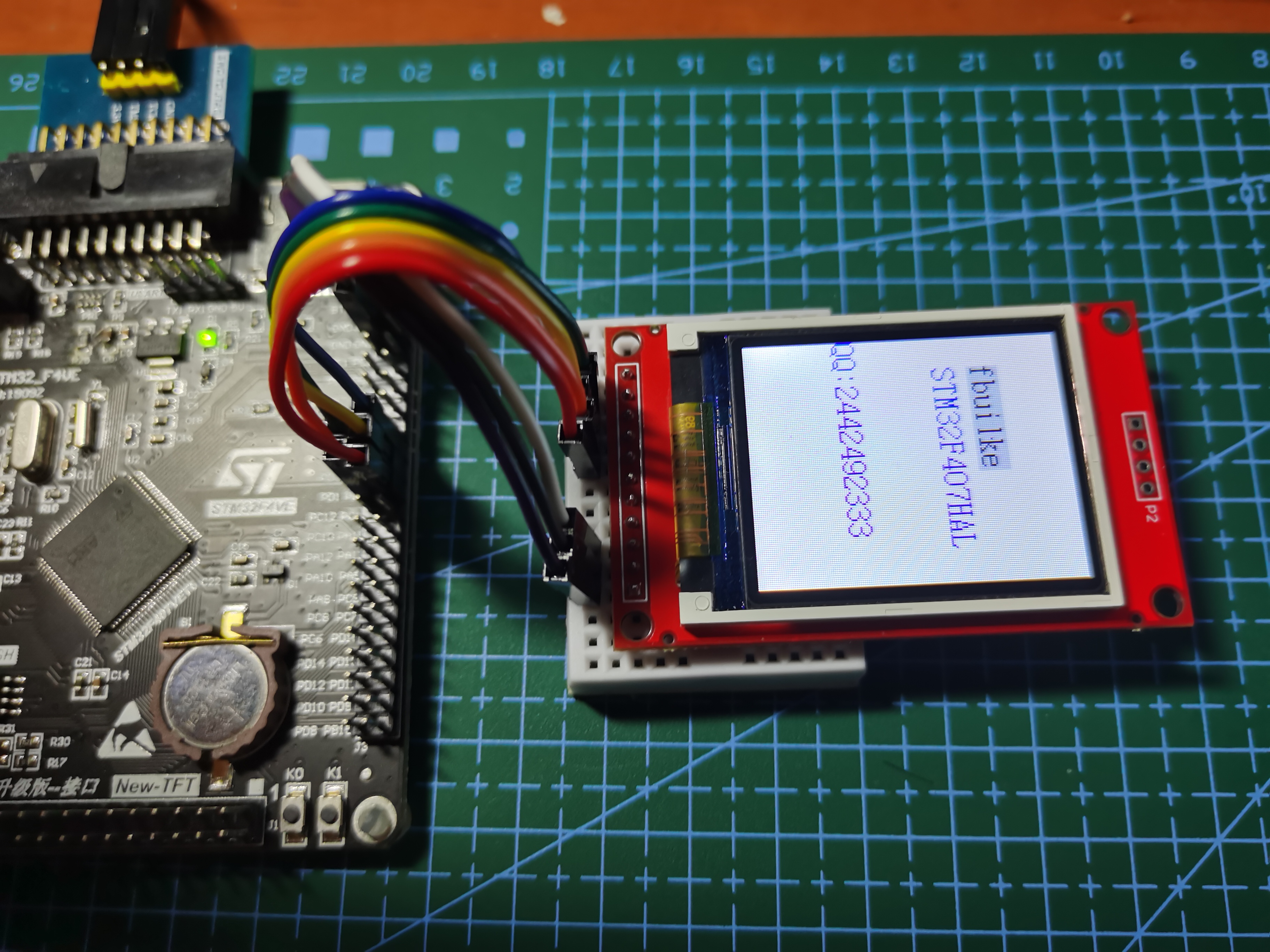
It can be seen that the screen refresh rate is quite fast, thanks to the increase of STM32F407IO rate
F103 is relatively slow
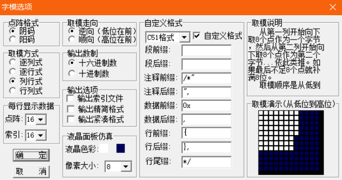
Mold taking part
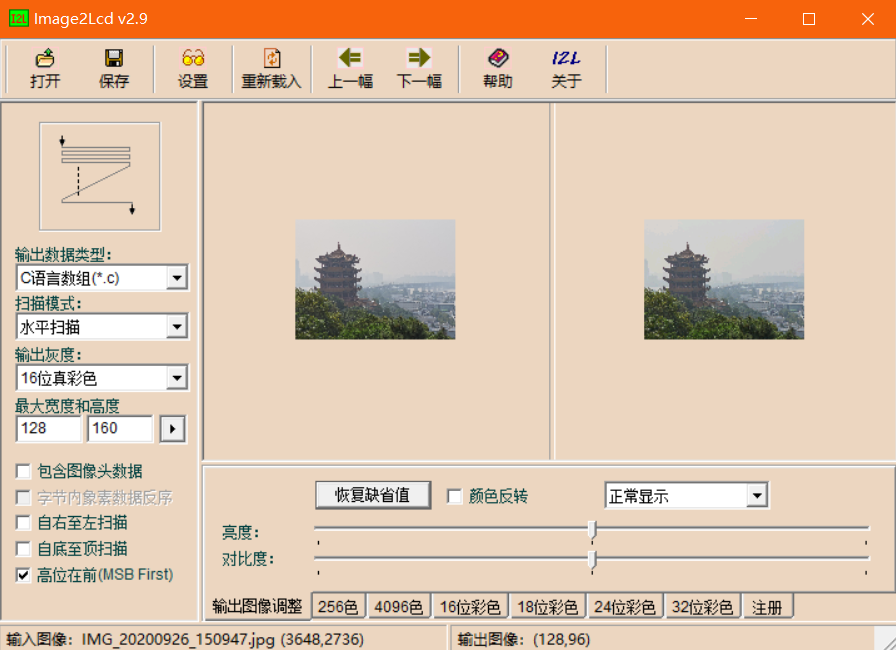
Image modeling
Text template
Of course, STM32F103C8T6HAL library is also transplanted. If necessary, leave a comment.
I've uploaded the code. Give me some points if you have points. Leave an email for comments if you don't have points