Design requirements
Use DMA to move data from memory A to memory B
1, Basic knowledge
DMA (Direct Memory Access) Direct Memory Access can greatly reduce the workload of CPU. The CPU executes instructions according to the content of the code. Among these instructions, there are instructions for calculation, control program and data transfer, especially transferring a large amount of data, which will occupy a large amount of CPU. If the data of peripheral A is transmitted to peripheral B, the CPU does not need to be involved all the time. Just create a channel between a and B and let them transmit it by themselves. This is the purpose of DMA design to reduce the CPU consumption of a large number of data transfer instructions. DMA focuses on data transfer and CPU focuses on calculation and control
DMA is mainly used to directly transfer the data at A to B. here A and B can be memory or peripherals. Therefore, all scenarios are as follows
- Memory to peripherals
- Peripheral to memory
- Memory to memory
- Peripheral to peripheral
Regardless of the above methods, the data source address, data destination address and data length of DMA are set first. After setting, start DMA to automatically transfer the data from the source address to the destination address.
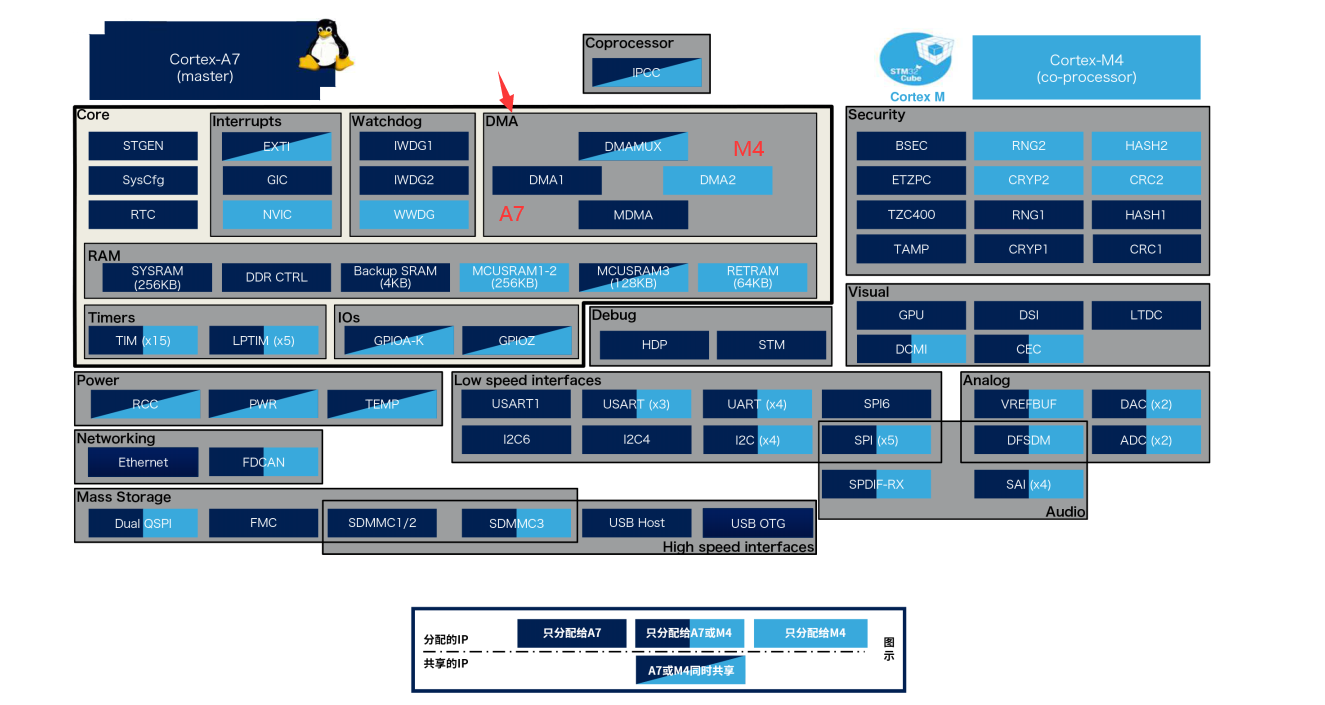 As can be seen from the above figure, STM32MP157 has four DMAS, among which DMA1 and MSMA are exclusive to A7, DMAMUX needs to specify A7 or M4, and DMA2 is exclusive to M4.
Here is the use of DMA2 to demonstrate how to set DMA handling data. Later, DMA will be used in other peripheral chapters.
2, Stm32cube ide design
1. Hardware design
Circuit design is not involved
2.MX design
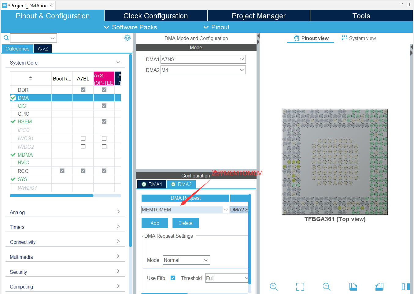
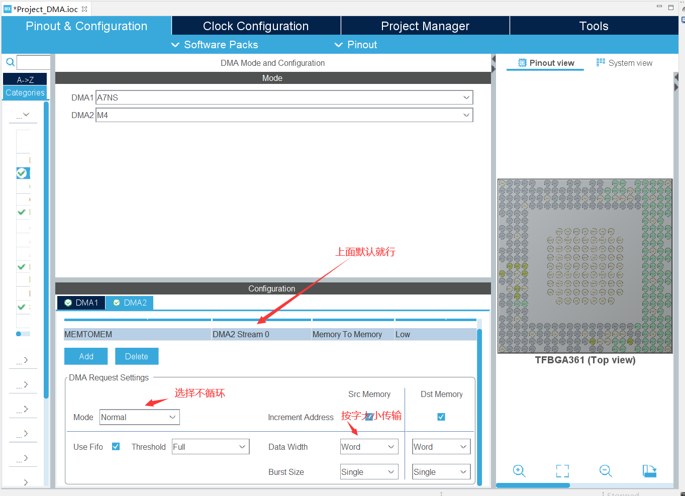
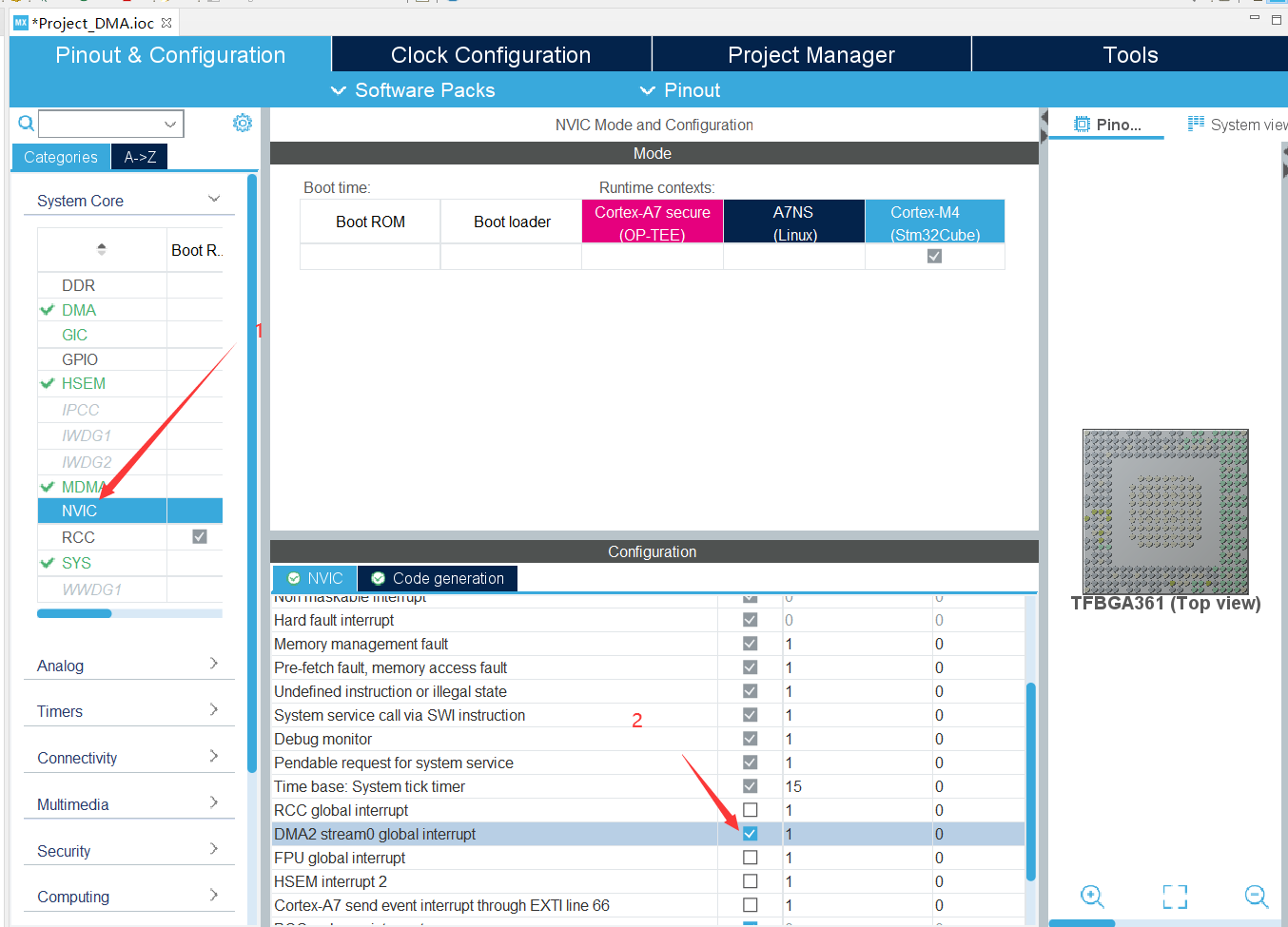
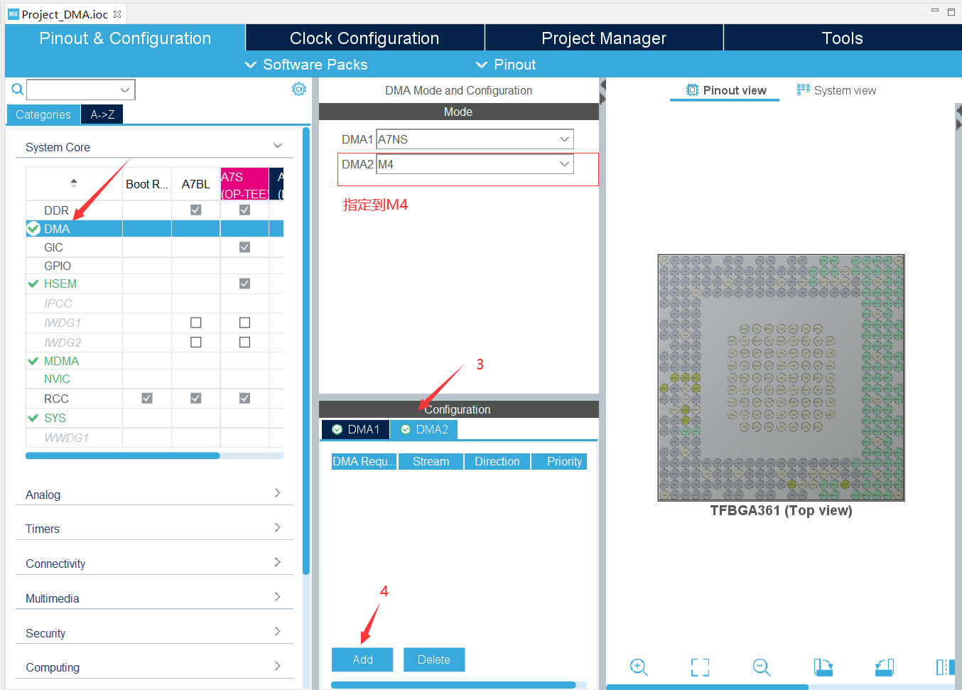 Configure DMA2
 After DMA completes data handling, an interrupt needs to be set to inform the completion of handling, so DMA interrupt needs to be set
Code design
driver_dma.h
/*
 * driver_dma.h
 *
 *  Created on: Jan 4, 2022
 *      Author: lenovo
 */

#ifndef DRIVER_DMA_H_
#define DRIVER_DMA_H_

#include "main.h"
#include "stm32mp1xx_hal.h"

extern __IO uint32_t transferErrorDetected;
extern __IO uint32_t transferCompleteDetected;


#endif /* DRIVER_DMA_H_ */
driver_dma.c
/*
 * driver_dma.c
 *
 *  Created on: Jan 4, 2022
 *      Author: lenovo
 */

#include "driver_dma.h"

__IO uint32_t transferErrorDetected;  //Transmission error detection
__IO uint32_t transferCompleteDetected; //Transmission completion detection

static void TransferComplete(DMA_HandleTypeDef *DmaHandle);
static void TransferError(DMA_HandleTypeDef *Dmahanle);

//Registering Callbacks
void RegisterCallbackFunction(void){
	//Register transfer completion and transfer error callback functions
	HAL_DMA_RegisterCallback(&hdma_memtomem_dma2_stream0,HAL_DMA_XFER_CPLT_CB_ID,TransferComplete);
	HAL_DMA_RegisterCallback(&hdma_memtomem_dma2_stream0,HAL_DMA_XFER_ERROR_CB_ID,TransferError);

	//Configure DMA interrupt priority and its enabling (generated automatically by the system)
	//HAL_NVIC_SetPriority(DMA2_Stream0_IRQn,0,0);
	//HAL_NVIC_EnableIRQ(DMA2_Stream0_IRQn);
}

//Input parameter: dmahandle DMA handle
//Function function: if DMA transfer is completed and no error occurs, set the transfer completion flag to 1 in this function

static void TransferComplete(DMA_HandleTypeDef *DmaHandle){
	transferCompleteDetected=1;
}
//Input parameter: dmahandle DMA handle
//Function function: if an error occurs during DMA transmission, set the transmission error flag to 1 in this function
static void TransferError(DMA_HandleTypeDef *DmaHandle){
	transferErrorDetected=1;
}

/*Input parameter: srcAddr - original address of data
 * 		 dstAddr-DMA Destination address of the move
 * 		 bufsz-DMA The unit of data size to be moved is selected during initialization: word is set above
 * 		 The DMA-channel1 function initializes DMA-channel1, configures it to memory memory mode, and carries one word at a time, i.e. 4 bytes
*/

void DMA_M2M_Start(uint32_t *srcAddr,uint32_t *dstAddr,uint16_t bufsz){
	if(HAL_DMA_Start_IT(&hdma_memtomem_dma2_stream0,(uint32_t)srcAddr,(uint32_t)dstAddr,bufsz)!=HAL_OK){
		Error_Handler();
	}
}
main.c
/* USER CODE BEGIN Header */
/**
******************************************************************************
* @file : main.c
* @brief : Main program body
******************************************************************************
* @attention
*
* Copyright (c) 2022 STMicroelectronics.
* All rights reserved.
*
* This software is licensed under terms that can be found in the LICENSE file
* in the root directory of this software component.
* If no LICENSE file comes with this software, it is provided AS-IS.
*
******************************************************************************
*/
/* USER CODE END Header */
/* Includes ------------------------------------------------------------------*/
#include "main.h"
/* Private includes ----------------------------------------------------------*/
/* USER CODE BEGIN Includes */
/* USER CODE END Includes */
/* Private typedef -----------------------------------------------------------*/
/* USER CODE BEGIN PTD */
/* USER CODE END PTD */
/* Private define ------------------------------------------------------------*/
/* USER CODE BEGIN PD */
/* USER CODE END PD */
/* Private macro -------------------------------------------------------------*/
/* USER CODE BEGIN PM */
/* USER CODE END PM */
/* Private variables ---------------------------------------------------------*/
UART_HandleTypeDef huart4;
DMA_HandleTypeDef hdma_memtomem_dma2_stream0;
/* USER CODE BEGIN PV */
static uint32_t srcBuffer[20]={
0x1234, 0x5678, 0x9876, 0x4586, 0xABCD,
0x5678, 0xABCD, 0x4586, 0x4586, 0xABCD,
0xABCD, 0x5678, 0x4586, 0x9876, 0x1234,
0x1234, 0xABCD, 0x9876, 0x5678, 0xABCD,
};
static uint32_t dstBuffer[20]={0};
/* USER CODE END PV */
/* Private function prototypes -----------------------------------------------*/
void SystemClock_Config(void);
static void MX_DMA_Init(void);
static void MX_GPIO_Init(void);
static void MX_UART4_Init(void);
/* USER CODE BEGIN PFP */
/* USER CODE END PFP */
/* Private user code ---------------------------------------------------------*/
/* USER CODE BEGIN 0 */
/* USER CODE END 0 */
/**
* @brief The application entry point.
* @retval int
*/
int main(void)
{
/* USER CODE BEGIN 1 */
uint8_t i=0;
/* USER CODE END 1 */
/* MCU Configuration--------------------------------------------------------*/
/* Reset of all peripherals, Initializes the Flash interface and the Systick. */
HAL_Init();
/* USER CODE BEGIN Init */
/* USER CODE END Init */
if(IS_ENGINEERING_BOOT_MODE())
{
/* Configure the system clock */
SystemClock_Config();
}
/* USER CODE BEGIN SysInit */
/* USER CODE END SysInit */
/* Initialize all configured peripherals */
MX_DMA_Init();
MX_GPIO_Init();
MX_UART4_Init();
/* USER CODE BEGIN 2 */
printf("\rDMA Memory To Memory Test\n");
RegisterCallbackFunction();
transferCompleteDetected=0;
transferErrorDetected=0;
DMA_M2M_Start(srcBuffer,dstBuffer,20);//Start DMA data handling
/* USER CODE END 2 */
/* Infinite loop */
/* USER CODE BEGIN WHILE */
while (1)
{
/* USER CODE END WHILE */
/* USER CODE BEGIN 3 */
if(transferCompleteDetected==1){//Judge whether the previous DMA transfer is completed (the flag is modified in the callback function)
transferCompleteDetected=0;//Reset the data completion flag to 0
for(i=0;i<20;i++){
if(dstBuffer[i]!=srcBuffer[i]){//Is there any difference by comparison
printf("\rDMA Data Error\n");
}
}
if(i==20){//No difference indicates that the transmission is completed normally. Start the transmission test again
DMA_M2M_Start(srcBuffer,dstBuffer,20);
printf("\rDMA Test ok\n");
}
}else if(transferErrorDetected==1){
transferErrorDetected=0;
printf("\rDMA TransferData Error\n");
}
HAL_Delay(1000);
}
/* USER CODE END 3 */
}
/**
* @brief System Clock Configuration
* @retval None
*/
void SystemClock_Config(void)
{
RCC_OscInitTypeDef RCC_OscInitStruct = {0};
RCC_ClkInitTypeDef RCC_ClkInitStruct = {0};
/** Initializes the RCC Oscillators according to the specified parameters
* in the RCC_OscInitTypeDef structure.
*/
RCC_OscInitStruct.OscillatorType = RCC_OSCILLATORTYPE_HSI|RCC_OSCILLATORTYPE_LSI
|RCC_OSCILLATORTYPE_HSE;
RCC_OscInitStruct.HSEState = RCC_HSE_ON;
RCC_OscInitStruct.HSIState = RCC_HSI_ON;
RCC_OscInitStruct.HSICalibrationValue = 16;
RCC_OscInitStruct.HSIDivValue = RCC_HSI_DIV1;
RCC_OscInitStruct.LSIState = RCC_LSI_ON;
RCC_OscInitStruct.PLL.PLLState = RCC_PLL_NONE;
RCC_OscInitStruct.PLL2.PLLState = RCC_PLL_NONE;
RCC_OscInitStruct.PLL3.PLLState = RCC_PLL_ON;
RCC_OscInitStruct.PLL3.PLLSource = RCC_PLL3SOURCE_HSE;
RCC_OscInitStruct.PLL3.PLLM = 2;
RCC_OscInitStruct.PLL3.PLLN = 52;
RCC_OscInitStruct.PLL3.PLLP = 3;
RCC_OscInitStruct.PLL3.PLLQ = 2;
RCC_OscInitStruct.PLL3.PLLR = 2;
RCC_OscInitStruct.PLL3.PLLRGE = RCC_PLL3IFRANGE_1;
RCC_OscInitStruct.PLL3.PLLFRACV = 2048;
RCC_OscInitStruct.PLL3.PLLMODE = RCC_PLL_FRACTIONAL;
RCC_OscInitStruct.PLL4.PLLState = RCC_PLL_NONE;
if (HAL_RCC_OscConfig(&RCC_OscInitStruct) != HAL_OK)
{
Error_Handler();
}
/** RCC Clock Config
*/
RCC_ClkInitStruct.ClockType = RCC_CLOCKTYPE_HCLK|RCC_CLOCKTYPE_ACLK
|RCC_CLOCKTYPE_PCLK1|RCC_CLOCKTYPE_PCLK2
|RCC_CLOCKTYPE_PCLK3|RCC_CLOCKTYPE_PCLK4
|RCC_CLOCKTYPE_PCLK5;
RCC_ClkInitStruct.AXISSInit.AXI_Clock = RCC_AXISSOURCE_HSI;
RCC_ClkInitStruct.AXISSInit.AXI_Div = RCC_AXI_DIV1;
RCC_ClkInitStruct.MCUInit.MCU_Clock = RCC_MCUSSOURCE_PLL3;
RCC_ClkInitStruct.MCUInit.MCU_Div = RCC_MCU_DIV1;
RCC_ClkInitStruct.APB4_Div = RCC_APB4_DIV1;
RCC_ClkInitStruct.APB5_Div = RCC_APB5_DIV1;
RCC_ClkInitStruct.APB1_Div = RCC_APB1_DIV2;
RCC_ClkInitStruct.APB2_Div = RCC_APB2_DIV2;
RCC_ClkInitStruct.APB3_Div = RCC_APB3_DIV2;
if (HAL_RCC_ClockConfig(&RCC_ClkInitStruct) != HAL_OK)
{
Error_Handler();
}
/** Set the HSE division factor for RTC clock
*/
__HAL_RCC_RTC_HSEDIV(1);
}
/**
* @brief UART4 Initialization Function
* @param None
* @retval None
*/
static void MX_UART4_Init(void)
{
/* USER CODE BEGIN UART4_Init 0 */
/* USER CODE END UART4_Init 0 */
/* USER CODE BEGIN UART4_Init 1 */
/* USER CODE END UART4_Init 1 */
huart4.Instance = UART4;
huart4.Init.BaudRate = 115200;
huart4.Init.WordLength = UART_WORDLENGTH_8B;
huart4.Init.StopBits = UART_STOPBITS_1;
huart4.Init.Parity = UART_PARITY_NONE;
huart4.Init.Mode = UART_MODE_TX_RX;
huart4.Init.HwFlowCtl = UART_HWCONTROL_NONE;
huart4.Init.OverSampling = UART_OVERSAMPLING_16;
huart4.Init.OneBitSampling = UART_ONE_BIT_SAMPLE_DISABLE;
huart4.Init.ClockPrescaler = UART_PRESCALER_DIV1;
huart4.AdvancedInit.AdvFeatureInit = UART_ADVFEATURE_NO_INIT;
if (HAL_UART_Init(&huart4) != HAL_OK)
{
Error_Handler();
}
if (HAL_UARTEx_SetTxFifoThreshold(&huart4, UART_TXFIFO_THRESHOLD_1_8) != HAL_OK)
{
Error_Handler();
}
if (HAL_UARTEx_SetRxFifoThreshold(&huart4, UART_RXFIFO_THRESHOLD_1_8) != HAL_OK)
{
Error_Handler();
}
if (HAL_UARTEx_DisableFifoMode(&huart4) != HAL_OK)
{
Error_Handler();
}
/* USER CODE BEGIN UART4_Init 2 */
/* USER CODE END UART4_Init 2 */
}
/**
* Enable DMA controller clock
* Configure DMA for memory to memory transfers
* hdma_memtomem_dma2_stream0
*/
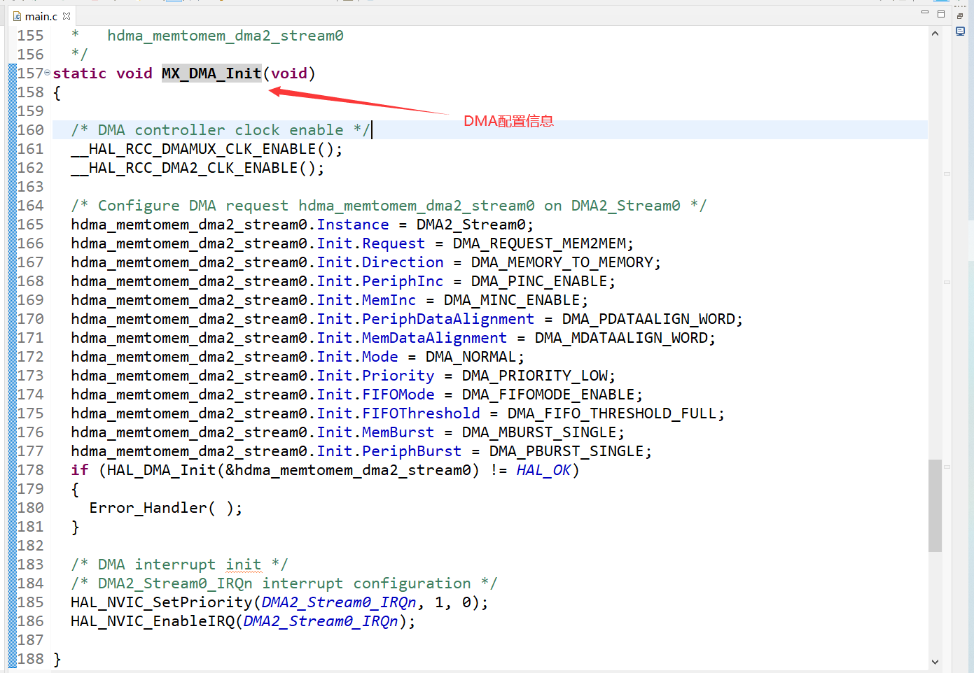
static void MX_DMA_Init(void)
{
/* DMA controller clock enable */
__HAL_RCC_DMAMUX_CLK_ENABLE();
__HAL_RCC_DMA2_CLK_ENABLE();
/* Configure DMA request hdma_memtomem_dma2_stream0 on DMA2_Stream0 */
hdma_memtomem_dma2_stream0.Instance = DMA2_Stream0;
hdma_memtomem_dma2_stream0.Init.Request = DMA_REQUEST_MEM2MEM;
hdma_memtomem_dma2_stream0.Init.Direction = DMA_MEMORY_TO_MEMORY;
hdma_memtomem_dma2_stream0.Init.PeriphInc = DMA_PINC_ENABLE;
hdma_memtomem_dma2_stream0.Init.MemInc = DMA_MINC_ENABLE;
hdma_memtomem_dma2_stream0.Init.PeriphDataAlignment = DMA_PDATAALIGN_WORD;
hdma_memtomem_dma2_stream0.Init.MemDataAlignment = DMA_MDATAALIGN_WORD;
hdma_memtomem_dma2_stream0.Init.Mode = DMA_NORMAL;
hdma_memtomem_dma2_stream0.Init.Priority = DMA_PRIORITY_LOW;
hdma_memtomem_dma2_stream0.Init.FIFOMode = DMA_FIFOMODE_ENABLE;
hdma_memtomem_dma2_stream0.Init.FIFOThreshold = DMA_FIFO_THRESHOLD_FULL;
hdma_memtomem_dma2_stream0.Init.MemBurst = DMA_MBURST_SINGLE;
hdma_memtomem_dma2_stream0.Init.PeriphBurst = DMA_PBURST_SINGLE;
if (HAL_DMA_Init(&hdma_memtomem_dma2_stream0) != HAL_OK)
{
Error_Handler( );
}
/* DMA interrupt init */
/* DMA2_Stream0_IRQn interrupt configuration */
HAL_NVIC_SetPriority(DMA2_Stream0_IRQn, 1, 0);
HAL_NVIC_EnableIRQ(DMA2_Stream0_IRQn);
}
/**
* @brief GPIO Initialization Function
* @param None
* @retval None
*/
static void MX_GPIO_Init(void)
{
/* GPIO Ports Clock Enable */
__HAL_RCC_GPIOH_CLK_ENABLE();
__HAL_RCC_GPIOA_CLK_ENABLE();
}
/* USER CODE BEGIN 4 */
/* USER CODE END 4 */
/**
* @brief This function is executed in case of error occurrence.
* @retval None
*/
void Error_Handler(void)
{
/* USER CODE BEGIN Error_Handler_Debug */
/* User can add his own implementation to report the HAL error return state */
__disable_irq();
while (1)
{
}
/* USER CODE END Error_Handler_Debug */
}
#ifdef USE_FULL_ASSERT
/**
* @brief Reports the name of the source file and the source line number
* where the assert_param error has occurred.
* @param file: pointer to the source file name
* @param line: assert_param error line source number
* @retval None
*/
void assert_failed(uint8_t *file, uint32_t line)
{
/* USER CODE BEGIN 6 */
/* User can add his own implementation to report the file name and line number,
ex: printf("Wrong parameters value: file %s on line %d\r\n", file, line) */
/* USER CODE END 6 */
}
#endif /* USE_FULL_ASSERT */
**Note: * * the following configuration information can be ignored
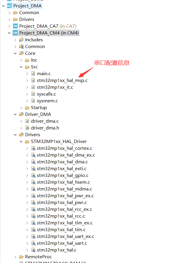
Project directory structure
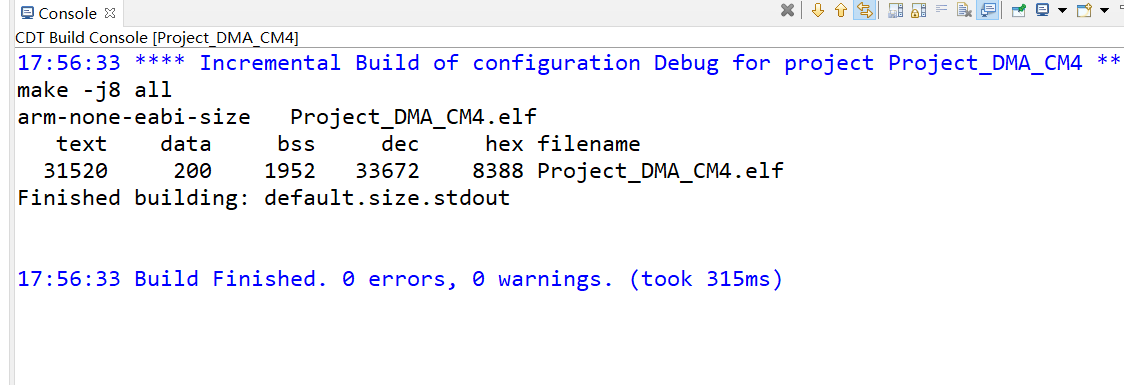
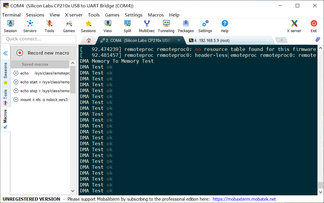
Operation results:
Experimental phenomenon
summary
Perfect, spend more time studying, these things will suddenly open up. come on.