Multiple memory access
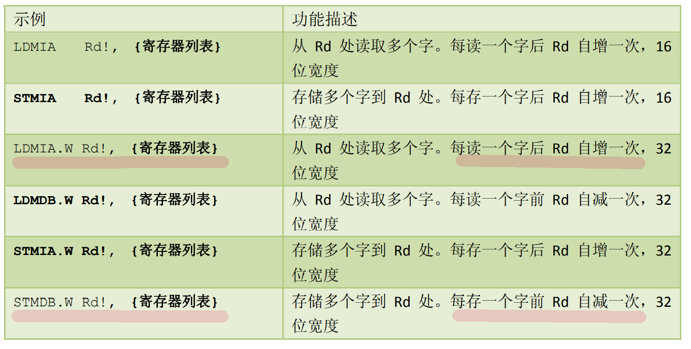
exclamatory mark! Indicates the value of the base register Rd to be incremented or decremented. The timing is before or after each access. Increase / decrease in words (4 bytes).
Ldr R1,=0x10000000          //Starting address of transmitted data 0x10000000

LDMIA R1!,{R0,R4-R6}         //Load from left to right, equivalent to LDR r010000000 and LDR r4100000004

/*Add + 4 to the address after transmission,

So R0=0X10000000, add 4 to the address,

R4=0X10000004 The content in the address, add 4 to the address,

R5=0X10000008 The content in the address, add 4 to the address,

R6=0X1000000C The content in the address, add 4 to the address,

because!, The last address is written back to R1, so R1 = 0x100000010   */
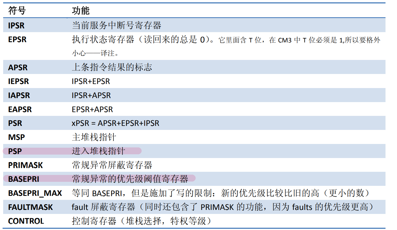
MRS and MSR
These two instructions are "green channels" to access special function registers - of course, they must be at the privilege level.
MRS <Rn>, <SReg> ;Load the value of the special function register to Rn
MSR <Sreg>,<Rn> ;storage Rn To the special function register
Example of specifying PSP to update:
LDR R0, =0x20008000
MSR PSP, R0
BX LR ;If you are returning from an exception to the thread state, use the new PSP The value of is used as the stack top pointer
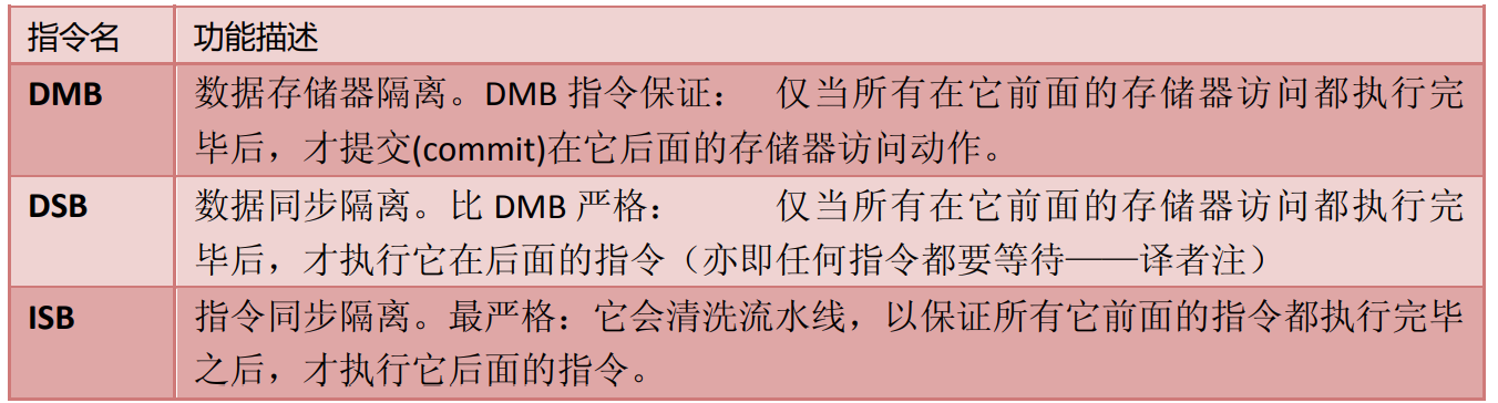
isb and dsb
ISB: if a program updates itself from the next instruction to be executed, but the previous old instruction has been prefetched into the pipeline, the pipeline must be cleaned, the old version of the instruction must be washed out, and then the new version of the instruction must be prefetched. Therefore, ISB must be used in front of the updated code segment to ensure that the old code is cleaned out of the pipeline and has no chance to execute.
DSB: if the vector table is relocated to RAM and the memory area of this RAM is write buffered, the vector update may be delayed. Just in case, a "data synchronization isolation (DSB)" instruction must be added after all vectors are established to wait for buffer write before continuing, so as to ensure that all data has been implemented.
DSB: if the mapping relationship of memory or the setting of memory protection area can be changed at runtime, a DSB instruction (data synchronization instruction) must be added immediately after the change. Because writes to MMU/MPU are likely to be put into a write buffer. Write buffer is designed to improve the overall access efficiency of memory, but it also has side effects. One of them is that it will delay the execution of instructions to write memory by several cycles. Therefore, the setting of memory cannot take effect immediately, which will cause the next instruction to still use the old memory setting.
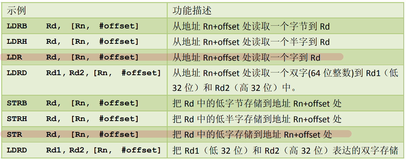
ldr and str
The basic instructions used to access memory are Load and Store.
ldr command: load data from memory into registers.
ldr r0, =addr	;r0 = addr
ldr r1, [r0]		; r1 = *r0 r0 The content pointed to r1
ldr r1, [r0, #4]	; r1 = *(r0+4)
ldr r1, [r0, #4] !	; r1 = *(r0+4);r0=r0+4;
ldr r1, [r0], #4	; r1 = *(r0);r0=r0+4;
str command: save data from register to memory.
str r1, [r0]		; *r0 = r1 r1 Value of as r0 Content of
str r1, [r0, #4]	; *(r0+4) = r1
str r1, [r0, #4] !	; *(r0+4) = r1;r0=r0+4;
str r1, [r0], #4	; *r0 = r1;r0=r0+4;
LDR R3, =MY_NUMBER ; R3= MY_NUMBER
LDR R4, [R3] ; R4= *R3,That is to put R3 The content pointed to R4
Assemblers usually support "LDR Rd, = imm32" pseudo instructions. (LDR has many connotations)
LDR r0, =0x12345678
mov
MOV register loading data can be used not only for transmission between registers, but also for loading immediate numbers.
MOV R8,    R3     ;hold R3 Data transfer to R8
MOV R0, #0x12     ;16 bit instruction MOV supports 8-bit immediate number loading
bl and bx
BL transfer and connect. It is used to call a subroutine, and the return address is stored in LR.
Subroutine call and unconditional transfer instruction:
BL Label ;Transfer to Label And save the address of the next instruction before the transfer to LR
BX reg  ;Transfer to by register reg Address given
In BX, the lowest bit of reg indicates whether ARM(LSB=0) or Thumb(LSB=1) will enter after the transfer. Since CM3 only runs in Thumb, you must ensure that the LSB of reg = 1. About BX this instruction, it was also mentioned in the previous interrupt section.
cps
In order to quickly switch interrupt, CM3 has specially set CPS instruction, which has four uses:
CPSID I ;PRIMASK=1, ;Off interrupt
CPSIE I ;PRIMASK=0, ;Open interrupt
CPSID F ;FAULTMASK=1, ;Guan anomaly
CPSIE F ;FAULTMASK=0 ;Abnormal opening