1, interface introduction
1.1 background of interface generation
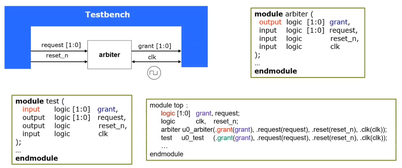
Traditional Verilog connects Testbench and DUT: name mapping and location mapping.

SystemVerilog improves and supplements the connection mode of Verilog and introduces the interface.
1.2 use mode of interface
- The connection can be realized directly through the instantiated name of the interface;
- The connection can be realized through the signal defined in the interface;

The interface in SV is the communication model between blocks, and the interface can be regarded as a bundle of intelligent connections. Interfaces include connection, synchronization, and even communication between two or more blocks. They connect the design and test platform. It has the following characteristics:
- The interface contains a set of signals;
- interface can be an independent file, which centralizes the signals common to multiple modules in one file;
- Multiple Verilog type signals are collected in the interface, which is an independent port type;
- The interface can contain multiple modport s and define different view s (DUT, Test program) of the interface
- In the interface, the clocking module can be used to explicitly indicate the synchronization clock domain;
- Clocking in the interface is only used to verify the platform, which can include multiple clocking modules. The signal direction in clocking is related to Testbench;
2, Sample code
2.1,DUT
The following is a simple arbiter RTL (DUT) code ARB v:
module arb(                  //Simple arbiter
           input    reset_n,
           input    clk,
           input    request,
           output reg  grant);

  always @(posedge clk or negedge reset_n) begin
     if(reset_n == 1'b0)begin
        grant <= 1'b0;
     end
     else if(request == 1'b1)begin
        grant <= 1'b1;
     end
     else if(request == 1'b0)begin
        grant <= 1'b0;
     end
  end

endmodule
2.2,Interface
interface file arb_if.sv:
interface arb_if(input bit clk);   //The clock signal is usually declared in the port list of the interface
       logic      grant;
       logic      request;
       logic      reset_n;

    clocking cb@(posedge clk);      //It is used to synchronize the clock domain, which is equivalent to a register and register the signal for one beat
       input      grant;            //The clocking module mainly serves TB
       output     request;
    endclocking

    modport TB(                    //Define TB view
        clocking   cb,
        output     reset_n);

    modport dut(                    //Define dut view
        input      request,
        input      reset_n,
        output     grant);

endinterface
Incentive file test Sv: usually written in program blocks, you can implicitly execute $finish; System function end code block.
2.3,TestBench
program test(arb_if.TB arbif);     //TB view in instantiated interface

   initial begin
      //Asynch drive reset_n
      arbif.cb.request <= 1'b0;      //Send the request to the DUT through the top edge of the clock clk
      arbif.reset_n <= 1'b1;         //Reset in TB_ N and request are asynchronous, and cb is not required
      #15  arbif. reset_ n <= 1'b0;    // Reset, stability circuit
      #35  arbif. reset_ n <= 1'b1;    // Evacuation reset
      #5;
      //Synch drive request
      //repeat(5)begin
          arbif.cb.request <= 1'b1;   //TB passes CB through the upper edge of clk The request is sent to the DUT, and the DUT will output a DUT Grant and pass it back to TB(cb.grant)
          wait(arbif.cb.grant <= 1'b1;);  //TB pair CB received from DUT(dut.grant) Grant judges and completes an information exchange
          arbif.cb.request <= 1'b0;
          @arbif.cb;    //@(posedge clk);
          @arbif.cb;
          @arbif.cb;
      //end
   end

endprogram            //The program module does not need the $finish function to end the excitation
2.4,Top
Top level file arb_tb.sv: package interface file, incentive file and DUT file
module ARB_TB();
    bit      clk;
    arb_if   arbif(.*);    //Implicit instantiation interface (the same as CLK signal name), equivalent to arb_if arbif(.clk(clk));
    test     u_test(.*);   //Privacy incentive file
    arb      u_arb(        //Connect TB and DUT through interface
                  .reset_n(arbif.reset_n),
                  .clk    (clk),
                  .request(arbif.request),
                  .grant  (arbif.grant)
               );
     initial begin
        clk = 0;
        forever #10 clk = ~clk;
     end

endmodule
- . * it will automatically connect the signal in the Interface!
3, Running simulation
3.1. Open Questasim
Because only the test incentive is written, neither the monitor nor the automatic comparison Makefile is written, so Questasim is used to view the waveform. The opening command is as follows
vsim &
If Questasim has started a project, you need to close it first, and then create a new project by using the GUI. (Reference: [quick start of Digital IC Verification] 6. Quick start of Questasim )Follow the link above to create, compile and start the simulation project.
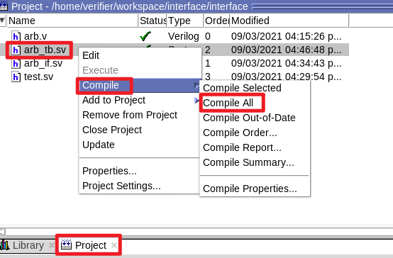
3. Compilation
3.3 simulation

3.4. Add waveform
If only the waveform of the DUT is added, the following steps can be followed: select u in the sim window_ ARB, select Add Wave or ctrl+w, as shown in the following figure:

Then select Run -ALL in the Wave column. When the simulation whether to end appears, be sure to select NO, as shown in the following figure:


You can compare the DUT code and check the waveform, and you can find that it meets the expectation.
3.5 in depth analysis of waveform
3.5.1 add all waveforms
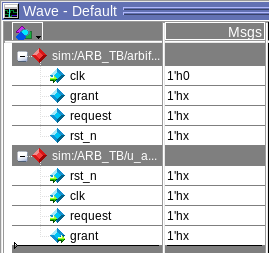
Here we choose arb_if and u_arb, add all waveforms to the wave window. (shortcut key ctrl+w)


Then in the wave window, ctrl+a selects all waveforms, and then ctrl+g groups the waveforms!

Knock out the signal name prefix and click the toggle leaf names < - > full names option in the lower left corner of the interface, as shown in the following figure:

Then in the menu bar, select restart, run -All
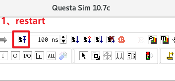
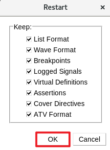
It should be noted that after clicking run -All, a prompt box will pop up whether to exit the simulation (implicitly execute $finish). We should select No, otherwise we will exit without seeing the waveform interface!

Then you can see that the waveform is crowded at the beginning. We make it fill the whole screen as follows:
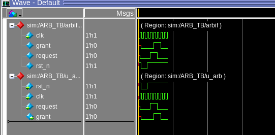
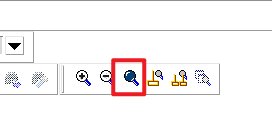

3.5.2 waveform analysis
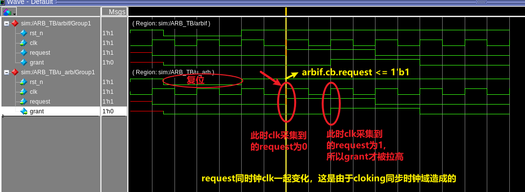
For the waveform diagram, pay attention to the coincidence of the number of clock edges and the change edges of data. At this time, due to the data delay, the clock edge usually collects the state data before the data change edge. As shown in the DUT below:
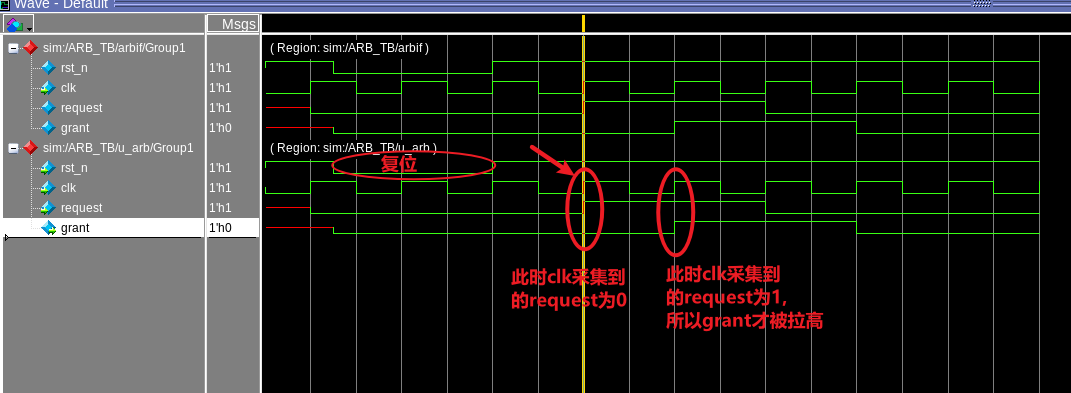
At the same time, pay attention to the role of clocking in the synchronization clock domain of signals.
