This article explains the API s of pinctrl subsystem and gpio subsystem, as well as examples.
The traditional way to configure the pin is to directly operate the corresponding registers, but this configuration method is cumbersome and prone to problems (such as pin function conflict). Pinctrl subsystem is introduced to solve this problem. The main work contents of pinctrl subsystem are as follows:
① . obtain the pin information in the device tree.
② . set the pin multiplexing function according to the obtained pin information
③ Set the electrical characteristics of the pin according to the obtained pin information, such as up / down, speed, driving capacity, etc.
For our users, we only need to set the relevant attributes of a pin in the device tree, and other initialization work is completed by the pinctrl subsystem.
If pinctrl initializes a pin pin to GPIO instead of IIC or SPI, then you can use the API of the GPIO subsystem.
GPIO subsystem is based on pinctrl subsystem! pin controller and GPIO Controller are not the same thing. The former control pin can be used for functional switching such as GPIO function and I2C function; The latter only configures the pin as input, output, setting GPIO direction, obtaining value and other simple functions. (pinctrl api can actually meet all requirements, but GPIO functions are more commonly used)
1. gpio subsystem API
The following steps are required to operate a GPIO in the GPIO subsystem:
1,of_find_compatible_node
2,of_get_named_gpio
3,gpio_request
4,control gpio(gpio_direction_input,gpio_direction_output......)
5,gpio_free
1)of_ find_ compatible_ The node function is based on device in the device tree_ The type and compatible attributes find the specified node. This is to obtain the node handle of GPIO set in the device tree. If you get a handle elsewhere, you can use it directly.
2) of_get_named_gpio, get the set gpio number.
3) gpio_request, request this GPIO. If this GPIO is requested elsewhere and has not been released, we will not be able to request it.
4) After requesting this gpio, we can operate on it, such as obtaining its value and setting its value.
5) After use, release the gpio.
schematic diagram:
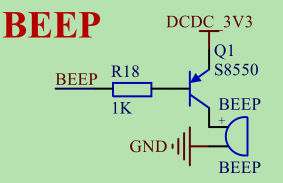
The blogger has a punctual atomic imx6ull development board in his hand. Check the schematic diagram and find that the GPIO directly connected to the buzzer is GPIO5_1. If I pull down this IO port, the buzzer will ring.
Add the following code in the device tree (imx6ull alientek EMMC. DTS)
test:test {
 compatible = "Jason_hello";
 hello = <&gpio5 1 GPIO_ACTIVE_HIGH>;
};
Set GPIO to GPIO5_1. The high level is valid, but in fact, I didn't use the third parameter.
gpio.c
#include <linux/init.h>
#include <linux/kernel.h>
#include <linux/module.h>
#include <linux/gpio.h>
#include <linux/of.h>
#include <linux/of_gpio.h>

static int __init mypinctrl_init(void)
{
 int gpionum = 0;
 int ret = 0;
 struct device_node *node = NULL;

 node = of_find_compatible_node(NULL,NULL,"Jason_hello");
 if(!node){
  printk("get node error\n");
  return ret;
 }

 gpionum = of_get_named_gpio(node,"hello",0);
 if(gpionum < 0){
  printk("get gpionum error\n");
  return ret;
 }

 ret = gpio_request(gpionum,"hello");
 if(ret){
  printk("gpio_request error\n");
  return ret;
 }

 printk("gpio(%d) value = %d\n",gpionum,ret);

 ret = gpio_get_value(gpionum);

 printk("gpio(%d) value = %d\n",gpionum,ret);

 gpio_direction_output(gpionum,0);  // Set gpio output low level

 ret = gpio_get_value(gpionum);

 printk("gpio(%d) value = %d\n",gpionum,ret);

 return 0;
}

static void __exit mypinctrl_exit(void)
{
 printk("%s\n",__func__);
}

module_init(mypinctrl_init);
module_exit(mypinctrl_exit);

MODULE_LICENSE("GPL");
Makefile
KERNELDIR := /home/book/linux/tool/kernel/linux-imx-rel_imx_4.1.15_2.1.0_ga_alientek

CURRENT_PATH := $(shell pwd)

obj-m := gpio.o

build: kernel_modules

kernel_modules:
 $(MAKE) -C $(KERNELDIR) M=$(CURRENT_PATH) modules
clean:
 $(MAKE) -C $(KERNELDIR) M=$(CURRENT_PATH) clean
Enter make dtbs in the root directory of Linux kernel source code, compile a device tree and download it into the development board.
Create a new folder in kernel/drivers/misc /, name it mygpio, and place GPIO C and Makefile. Then type make to compile GPIO ko. Then copy it into the board and insmod it. You can find that the buzzer rings.
2. pinctrl subsystem API
There are many API s for the pinctrl subsystem. For the driver engineer, pinctrl only needs three steps to operate a GPIO:
1,devm_pinctrl_get
2,pinctrl_lookup_state
3,pinctrl_select_state
In Linux, add devm_ The function at the beginning represents that this function supports resource management. Generally, when we write a driver, we will apply for resources at the beginning of the program, such as memory and interrupt number. In case there is an error in the later application, we have to roll back to the first step to release the applied resources, which is very troublesome. Later, Linux developed many devms_ The function at the beginning indicates that the function has a version that supports resource management. No matter which step goes wrong, as long as the error exits, the applied resources will be automatically released.
1)devm_pinctrl_get: used to obtain the handle of the node in the device tree established by itself with pinctrl;
2) pinctrl_lookup_state: used to select the state of one pinctrl. The same pinctrl can have many states. For example, GPIO50 is initialized with I2C at the beginning. When the device is standby, I want to switch to the normal GPIO mode and configure it as a pull-down input to save power. At this time, if the pinctrl node has a description, we can switch the function of pin in the code from I2C function to ordinary GPIO function;
3) pinctrl_select_stat: used for real setting. After obtaining a state in the previous step, this step is really set to this state.
The device tree configuration of the pinctrl subsystem follows the service and client structures.
Each platform on the client side is basically the same, each platform on the server side is different, and the configuration of the string used is also different.
Device tree configuration:
//client side, set different states
&test {
 pinctrl-names = "default","test_low","test_high";
 pinctrl-0 = <&test_default>;
 pinctrl-1 = <&test_low>;
 pinctrl-2 = <&test_high>;
 gpio = <&gpio5 1 GPIO_ACTIVE_LOW>;
 status = "okay";
};

//The server, that is, the pin controller, sets several GPIO function states
&gpio5 {
 test_default:test_default{};

 test_low:test_low{
  fsl,pins = <
   MX6UL_PAD_GPIO5_IO01__GPIO5_IO01 0x17059
  >
 };

 test_high:test_low{
  fsl,pins = <
   MX6UL_PAD_GPIO5_IO01__GPIO5_IO01 0x1b0b1
  >
 };
};
pinctrl.c
#include <linux/init.h>
#include <linux/kernel.h>
#include <linux/module.h>
#include <linux/platform_device.h>
#include <linux/delay.h>
#include <linux/pinctrl/pinctrl.h>
#include <linux/pinctrl/consumer.h>

static int __init mypinctrl_init(void)
{
 int ret = 0;
 struct pinctrl *pctrl;
 struct platform_device *pdev;
 struct pinctrl_state *test_high;
 struct pinctrl_state *test_low;

 pctrl = devm_pinctrl_get(&pdev->dev);
 if(IS_ERR(pctrl)){
  ret = PTR_ERR(pctrl);
  printk("devm_pinctrl_get error\n");
  return ret;
 }

 test_high = pinctrl_lookup_state(pctrl,"test_high");
 if(IS_ERR(pctrl)){
  ret = PTR_ERR(test_high);
  printk("pinctrl_lookup_state test_high error\n");
  return ret;
 }

 test_low = pinctrl_lookup_state(pctrl,"test_low");
 if(IS_ERR(pctrl)){
  ret = PTR_ERR(test_low);
  printk("pinctrl_lookup_state test_low error\n");
  return ret;
 }

 pinctrl_select_state(pctrl,test_low);
 udelay(200);
 pinctrl_select_state(pctrl,test_high);

 return 0;
}

static void __exit mypinctrl_exit(void)
{
 printk("%s\n",__func__);
}

module_init(mypinctrl_init);
module_exit(mypinctrl_exit);

MUDULE_LICENSE("GPL");
Makefile is the same as above, except to change the name of the compiled output.
When this driver is loaded, you can switch the function state of the GPIO port. I just control the GPIO output here. It depends on how your device tree is configured. For example, you can configure a GPIO with I2C function at the beginning and ordinary GPIO function at standby to save power.
Supplement:
The device tree is used to describe the device information on the board. Different devices have different information, which is reflected in the device tree. So where do we look up the relevant instructions when we add a node corresponding to the hardware in the device tree? There are detailed in the Linux kernel source code txt document describes how to add nodes, these txt document is called binding document, and the path is: Linux source directory / Documentation/devicetree/bindings.
For example, if we want to add a node under the I2C of the SOC I.MX6ULL, we can view the documentation / devicetree / bindings / I2C / I2C IMX Txt. This document describes in detail how the SOC of I.MX series adds I2C device nodes to the device tree.
Sometimes some chips used cannot find the corresponding documents in the Documentation/devicetree/bindings directory. At this time, consult the chip supplier and ask them to provide you with the reference device tree file.
Tip: many times we look at the device tree file, but we can't understand the contents. At this time, you can read it dts first refers to the header file. Click in and you will find that these strings are defined here.
Reference documents:
Documentation\devicetree\bindings\Pinctrl\Pinctrl-bindings.txt
Documentation\gpio\Pinctrl-bindings.txt
Documentation\devicetree\bindings\gpio\gpio.txt
Documentation\devicetree\bindings\pinctrl\pinctrl-bindings.txt