By chance, I met a 12-year-old Comrade online and systematically tutored his maker to develop thinking and skills from scratch.
Project column: https://blog.csdn.net/m0_38106923/category_11097422.html
I played flying chess when I was a child. Do you like to roll dice? Today I will make a number dice through Arduino.
How to achieve the effect of digital dice? In fact, it uses 8 LED digital segments.
Prospect review: Engage in maker development with 12-year-old comrades: how to drive LED nixie tubes?
In addition, a new module will be used: the Shiftout module.
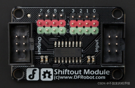
The Shiftout module is a 74HC595 serial input or parallel output shift register chip. If you want to understand the code, you need to have a simple understanding of the working principle of 74HC595 chip.
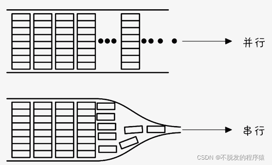
74HC595 realizes the function of serial input to parallel output. First, let's talk about serial and parallel. The following figure shows the difference between serial and parallel. Serial is sent one by one, while parallel is sent out with 8 digits.
74HC595 can process the data in serial and let it output in parallel. The advantage is that, for example, when we need to use multiple LEDs and the digital pins are not enough, we can control multiple LEDs at the same time with one 74HC595.
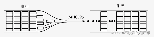
The output of a 74HC595 chip is also exactly 8 bits, so you can use the output of 74HC595 to control an 8-segment LED nixie tube.
The function of 74HC595 is to output 8 bits in parallel through a data port, which will not make the LED occupy 8 digital pins. Of course, if you want to connect 8 digital ports, there is no problem, but it will occupy a little more pins.
How to send data and what data? It is determined by the data, latch and clock pins.

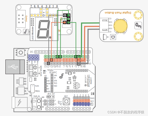
The project connection effect is as follows:
The implementation code is as follows:
int latchPin = 8;  //The digital port 8 is connected to the enable pin of the 74HC595 chip
int clockPin = 3;  //Digital port 3 is connected to the clock pin of 74HC595 chip
int dataPin = 9;   //The digital port 9 is connected to the data pin of the 74HC595 chip
int buttonPin = 2; // The button is connected to the digital port 2

//Representative numbers 0 ~ 9
byte Tab[]={
0xc0,0xf9,0xa4,0xb0,0x99,0x92,0x82,0xf8,0x80,0x90};

int number;
long randNumber;
void setup() {
    pinMode(latchPin, OUTPUT);
    pinMode(dataPin, OUTPUT);
    pinMode(clockPin, OUTPUT);
    randomSeed(analogRead(0));   //Set a random number generation source simulation port 0
}

void loop(){
    randNumber = random(10);   //Generate random numbers between 0 and 9
    showNumber(randNumber);    //Displays the random number

    //Once a key is pressed, the number is displayed and held until released
    while(digitalRead(buttonPin) == HIGH){
       delay(100);
    }
}

//This function is used for nixie tube display
void showNumber(int number){
     digitalWrite(latchPin, LOW);
     shiftOut(dataPin, clockPin, MSBFIRST, Tab[number]);
     digitalWrite(latchPin, HIGH);
     delay(80);
}
Let's talk about how to use the shiftOut() function?
shiftOut function format:
shiftOut(dataPin,clockPin,bitOrder, value)
- dataPin: pin that outputs each bit of data (int)
- clockPin: clock pin. When dataPin has a value, the level of this pin changes (int)
- bitOrder: the order of output bits, highest order first (MSBFIRST) or lowest order first (LSBFIRST)
- value: data to shift output (byte)
be careful:
- dataPin and clockPin should be set to OUTPUT in pinMode() of setup().
- At present, shiftOut can only output 1 byte (8 bits), so if the output value is greater than 255, it needs to be divided into two steps.
In the code, we can see that the order of output bits is the highest priority, and Tab[number] is the output data.
shiftOut(dataPin, clockPin, MSBFIRST, Tab[number]);
Let's see what's in Tab[number]?
//Representative numbers 0 ~ 9
byte Tab[]={
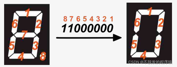
0xc0,0xf9,0xa4,0xb0,0x99,0x92,0x82,0xf8,0x80,0x90};Review of these prospects: Engage in maker development with 12-year-old comrades: how to drive LED nixie tubes? As mentioned in, it is the composition principle of nixie tube, which will not be repeated here.
Since we need to make digital dice, there is another important step. How to randomly generate numbers between 0 and 9? Arduino provides a useful function, random().
random (max)
Random() can generate random numbers and generate random numbers within the range of [0, max-1]. max is the maximum value.
random(10);//Generate a number between 0 and 9
The randonseed() function is used to set the random seed. We have received the simulation port 0 here.
randomSeed(analogRead(O));