Temperature and Humidity Collection and OLED Display Based on I2C/SPI
1.I2C interface for temperature and humidity (AHT20) collection
Introduction to I2C
1.I2C Introduction
I2C bus is a simple, two-way two-wire synchronous serial bus developed by Philips. It only requires two wires to transfer information between devices connected to the bus.
The main device is used to start the bus to transmit data and generate a clock to open the transmission. Any addressed device is considered a slave device at this time. The relationship between the master and slave, send and receive on the bus is not constant, but depends on the direction of data transmission at this time. If the host wants to send data to the slave device, the host addresses the slave device first, then actively sends data to the slave device, and finally terminates the data transfer by the host. If the host receives data from the device, the master addressing the slave device first, then the host receives data sent from the device, and finally the host terminates the receiving process. In this case, the host is responsible for generating a timer clock and terminating data transfer.
2. Software I2C
Direct use of the CPU core to control the GPIO output level to simulate I2C as required by the I2C protocol.
Use of software I2C
You need to control the GPIO pin as the SCL line to output a high level when you control the start signal of I2C, then control the GPIO pin as the SDA line to switch from high level to low level during this period, and finally control the SCL line to low level, so that a standard I2C start signal is output.
3. Hardware I2C
Direct use of hardware I2C peripherals in STM32 chips.
Use of hardware I2C
As long as the corresponding registers are configured, the peripherals will generate the timing of the standard serial protocol. After initializing the I2C peripheral, just need to locate a register at this time the peripheral will control the corresponding SCL and SDA lines to automatically generate the I2C start signal, no need for the kernel to directly control the pin level.
Implement temperature and humidity output
Find relevant code on the web http://www.aosong.com/class-36-2.html
Modify the main function yourself as follows
/* USER CODE BEGIN Header */
/**
******************************************************************************
* @file : main.c
* @brief : Main program body
******************************************************************************
* @attention
*
* <h2><center>© Copyright (c) 2021 STMicroelectronics.
* All rights reserved.</center></h2>
*
* This software component is licensed by ST under BSD 3-Clause license,
* the "License"; You may not use this file except in compliance with the
* License. You may obtain a copy of the License at:
* opensource.org/licenses/BSD-3-Clause
*
******************************************************************************
*/
/* USER CODE END Header */
/* Includes ------------------------------------------------------------------*/
#include "main.h"
#include "dma.h"
#include "i2c.h"
#include "usart.h"
#include "gpio.h"
/* Private includes ----------------------------------------------------------*/
/* USER CODE BEGIN Includes */
#include<stdio.h>
#include "AHT20-21_DEMO_V1_3.h"
void SystemClock_Config(void);
int fputc(int ch,FILE *f)
{
HAL_UART_Transmit(&huart1,(uint8_t *)&ch,1,0xFFFF);
//Waiting for Send to End
while(__HAL_UART_GET_FLAG(&huart1,UART_FLAG_TC)!=SET){
}
return ch;
}
int main(void)
{
/* USER CODE BEGIN 1 */
uint32_t CT_data[2]={0,0};
volatile int c1,t1;
Delay_1ms(500);
HAL_Init();
SystemClock_Config();
MX_GPIO_Init();
MX_DMA_Init();
MX_USART1_UART_Init();
//Initialize AHT20
AHT20_Init();
Delay_1ms(500);
while (1)
{
/* USER CODE END WHILE */
AHT20_Read_CTdata(CT_data); //Reading temperature and humidity data directly from AHT20 without CRC checking is recommended every time greater than 1S
//AHT20_ Read_ CTdata_ Crc(CT_data); // Read temperature and humidity data of AHT20 after CRC check
c1 = CT_data[0]*1000/1024/1024; //The calculated humidity value c1 (magnified 10 times)
t1 = CT_data[1]*2000/1024/1024-500;//The calculated temperature value t1 (magnified 10 times)
printf("Detecting");
HAL_Delay(100);
printf(".");
HAL_Delay(100);
printf(".");
HAL_Delay(100);
printf(".");
HAL_Delay(100);
printf(".");
HAL_Delay(100);
printf(".");
HAL_Delay(100);
printf(".");
HAL_Delay(100);
printf(".");
HAL_Delay(100);
printf(".");
HAL_Delay(100);
printf(".");
HAL_Delay(100);
printf(".");
printf("\r\n");
HAL_Delay(1000);
printf("temperature:%d%d.%d",t1/100,(t1/10)%10,t1%10);
printf("humidity:%d%d.%d",c1/100,(c1/10)%10,c1%10);
printf("\r\n");
printf("wait for");
HAL_Delay(100);
printf(".");
HAL_Delay(100);
printf(".");
HAL_Delay(100);
printf(".");
HAL_Delay(100);
printf(".");
HAL_Delay(100);
printf(".");
HAL_Delay(100);
printf(".");
HAL_Delay(100);
printf(".");
HAL_Delay(100);
printf(".");
HAL_Delay(100);
printf(".");
HAL_Delay(100);
printf(".");
printf("\r\n");
HAL_Delay(1000);
/* USER CODE END 3 */
}
}
/**
* @brief System Clock Configuration
* @retval None
*/
void SystemClock_Config(void)
{
RCC_OscInitTypeDef RCC_OscInitStruct = {0};
RCC_ClkInitTypeDef RCC_ClkInitStruct = {0};
/** Initializes the RCC Oscillators according to the specified parameters
* in the RCC_OscInitTypeDef structure.
*/
RCC_OscInitStruct.OscillatorType = RCC_OSCILLATORTYPE_HSI;
RCC_OscInitStruct.HSIState = RCC_HSI_ON;
RCC_OscInitStruct.HSICalibrationValue = RCC_HSICALIBRATION_DEFAULT;
RCC_OscInitStruct.PLL.PLLState = RCC_PLL_NONE;
if (HAL_RCC_OscConfig(&RCC_OscInitStruct) != HAL_OK)
{
Error_Handler();
}
/** Initializes the CPU, AHB and APB buses clocks
*/
RCC_ClkInitStruct.ClockType = RCC_CLOCKTYPE_HCLK|RCC_CLOCKTYPE_SYSCLK
|RCC_CLOCKTYPE_PCLK1|RCC_CLOCKTYPE_PCLK2;
RCC_ClkInitStruct.SYSCLKSource = RCC_SYSCLKSOURCE_HSI;
RCC_ClkInitStruct.AHBCLKDivider = RCC_SYSCLK_DIV1;
RCC_ClkInitStruct.APB1CLKDivider = RCC_HCLK_DIV1;
RCC_ClkInitStruct.APB2CLKDivider = RCC_HCLK_DIV1;
if (HAL_RCC_ClockConfig(&RCC_ClkInitStruct, FLASH_LATENCY_0) != HAL_OK)
{
Error_Handler();
}
}
/* USER CODE BEGIN 4 */
/* USER CODE END 4 */
/**
* @brief This function is executed in case of error occurrence.
* @retval None
*/
void Error_Handler(void)
{
/* USER CODE BEGIN Error_Handler_Debug */
/* User can add his own implementation to report the HAL error return state */
__disable_irq();
while (1)
{
}
/* USER CODE END Error_Handler_Debug */
}
#ifdef USE_FULL_ASSERT
/**
* @brief Reports the name of the source file and the source line number
* where the assert_param error has occurred.
* @param file: pointer to the source file name
* @param line: assert_param error line source number
* @retval None
*/
void assert_failed(uint8_t *file, uint32_t line)
{
/* USER CODE BEGIN 6 */
/* User can add his own implementation to report the file name and line number,
ex: printf("Wrong parameters value: file %s on line %d\r\n", file, line) */
/* USER CODE END 6 */
}
#endif /* USE_FULL_ASSERT */
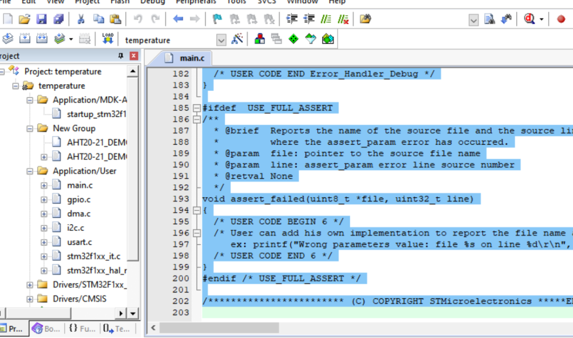
/************************ (C) COPYRIGHT STMicroelectronics *****END OF FILE****/
Reference and Reference https://blog.csdn.net/qq_43279579/article/details/111597278
2.0.96 inch OLED display data
Introduction to SPI
SPI is the abbreviation of Serial Peripheral Interface. SPI is a high-speed, full-duplex, synchronous communication bus. It is widely used in ADC, LCD and other communication processes with MCU, with the feature of fast. The Serial Peripheral Interface (SPI) bus was developed by Motorola to provide full duplex synchronous serial communication between primary and secondary devices.
Use OLED screen to display name and number
Get the necessary Chinese character dot matrix by software
Add your own name to the instance code
void TEST_MainPage(void)
{
	GUI_ShowCHinese(28,24,16,"XXX",1);//Show Chinese Name
	GUI_ShowString(4,48,"631907060414",16,1);//Show school number
	delay_ms(1500);
	delay_ms(1500);
}
give the result as follows
summary
This experiment learns the I2C bus communication protocol, understands the principle of OLED display and Chinese character dot matrix encoding, and uses the SPI interface of STM32F103 to realize OLED display data.